User:Ac001/ILS
| Flight College |
|---|
Flying approaches with ILS
Its recommended you read the summary and intro paragraphs to the subjects below and familiarise yourself with the concepts and workings (thanks wikipedia and everyone):-
- PAPI - Precision Approach Path Indicator which is a Visual Approach Slope Indicator VASI
- ILS - Instrument Landing System
- DME - Distance Measuring Equipment
- IAP - Instrument Approach Procedure
- PFD - Primary Flight Display
The Route
The route is over central London between:
- EGLC London City Airport (Charts) - A single 1500ft runway 6nm east of central London on reclaimed docklands.
- EGLL London Heathrow in the west (Charts) - Two large parallel runways 4000ft in length.
EGLC is unusual as it has a steeper 5.05 degree Glideslope instead of the normal 3.00 degree which makes the approach a bit trickier; ooh and a 771ft skyscraper on the RWY 10 approach path.
Final Approach
This chart is typically found on all approach plates. This is a final approach to RWY 27L, ie right to left. The glideslope is the standard 3 degree.
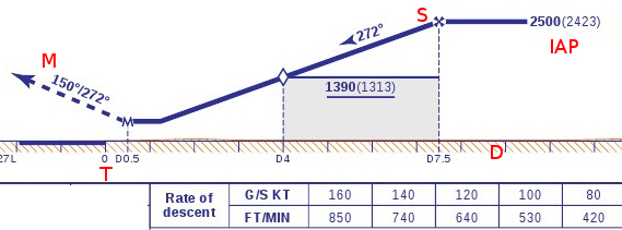
- The terrain is almost flat, indicated by a the brown line across the bottom.
- T - is the threshold of the runway 27L indicated by the blue line.
- D - is this is the distance marked in nm from the threshold. The runway is just short of 2nm in length.
- IAP - this is the Initial Approach to 27L from the Initial Approach Fix. The aircraft is expected to approach the runway at 2500ft AMSL (2423 AGL).
- S - this is the start of the descent glidescope, a point 7.5nm from the runway threshold. The ILS beam is expected to have been in range and intercepted at this point.
- 4nm from the threshold, the aircraft is expected to be at 1390 AMSL, fully configured, gear down and prepared to land. Around this point final landing clearance will be given.
- 0.5nm from the threshold (a blue M) is both the Decision Height and Missed Approach Point. If any condition such as airspeed, height, alignment etc are not within limits, aircraft or camels on the runway etc, then a Missed Approach and Go Around is executed.
- The red M - is the missed approach instruction, ie climb straight ahead heading 272, and then probably follow ATC instruction to vector in with other traffic arriving at the Initial Approach.
- The chart at the bottom shows the Rate Of Descent at various ground speeds.
On a standard 3 degree slope, rate of descent can be roughly calculated as:
Rate of descent = ground speed × 5
eg
120 kts × 5 = 600 feet per minute
Example Approaches
To "visualise" the enviroment before performing a flight, first presented is a map and cockpit view of two aircraft on two different approaches:
- EGLL 27L - Heathrow Approach - threshold elevation 77ft, length 3660m in a Rutan designed Beechcraft Starship.
- EGLC 10 - City Approach - threshold elevation 16ft, length 1500m in a Citation Bravo.
- then its time to fly and buzz some runways.
Heathrow Approach
Following is a snapshot of the map and cockpit of an approach to EGLL 27L, the aircraft is a Beechcraft Starship, being flown manually.
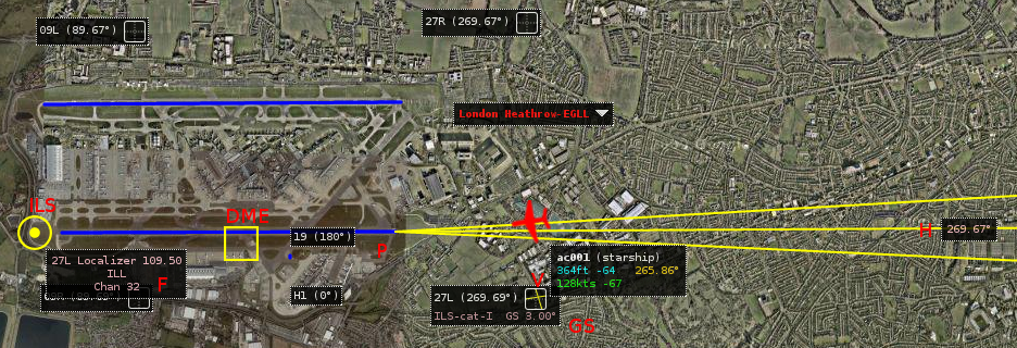
EGLL 27L Map View
- V - clicking the "button box" brings up the ILS details of RWY 27L on MultiplayerMap
- ILS - the antenna array indicated by a circle and dot is located beyond the end of 27L, ie 09L
- F - the frequency of the localiser is 109.5
- GS - the glidescope is the standard 3.0 degree
- DME - the yellow square is the DME transponder near the middle of the runway, and used by the ILS at both ends.
- H - the magnetic heading for this runway is 269.67
- P - the approximate location of the PAPI lights.
EGLL 27L Cockpit view
The ILS has been selected by pressing F11, bringing up the radio frequencies.
- NAV1 is tuned to 109.5
- The heading has been set to 270, pointing at the localiser. The localiser unlike a VOR has a "kinda fixed radial"
- DME is "automatically" selected as a sideband, and is used by the ILS on both approaches.
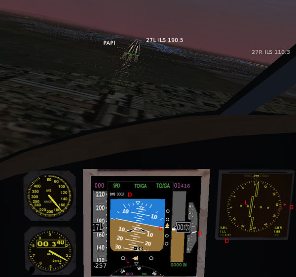
The screenshot below shows the pilots view of the approach. The parallel runway 27R is visible towards the top right. The airspeed it high at 170 knots and as an approach is not good; however this it demonstrates the ILS instruments better.
GlideSlope
The aircraft is slightly below the glideslope indicated by:
- The PAPI lights to the left of the touch down zone - Three reds and one white means the pilots eyes are below the glidescope. Two white and two red is perfect approach. Four reds is not good.
- G on the right side of both the PFD and the NAV panel - The little diamond is above the line which means the aircraft
should be higher to be "on" the glideslope.
- R on the right side of the PFD shows a Descent Rate of 1000fpm (feet per minute)
To correct the position, a normal response would be to just pull back the stick slightly to lower the rate of descent indicated on the right of the PFD.
Localiser
The aircraft is to the right of the center line and needs to move left for correction. This is indicated via:
- L on the bottom of the PFD - The diamond is to the left of the line, this means the aircraft needs to move left to align with the runway center line.
- L on the NAV panel. The aircraft needs to move to the left to be heading directly at the localiser radial.
To correct, a response would be to use the rudder pedals to correct alignment.
Distance
The distance to the DME transponder located near the middle of the runway is displayed on:
- D top left of the PFD - The distance is 0.7 nautical miles
- D on the bottom left of the NAV panel - The distance in 0.7 nm which is not very clear.
- The threshold is around 0.7nm - 1800m away
Speed
- The aircraft is travelling at around 160 knots which is fast for this class, it should be around 100+ knots.
- The aircraft needs to slow down to avoid a difficult landing.
Conclusions
This approach is recoverable as the runway is very long and a Beechcraft can travel pretty slow.
- Raising the nose to gain height to fly level before recapturing the glideslope.
- The airspeed will decrease as the nose raises, throttling back the engines avoiding stall.
- Aligning with the runway localiser.
- Gracefuly flaring further down the runway once positined over the centre line.
London City Approach
Following is a snapshot of the map and cockpit of an approach to EGLC RWY 10. The aircraft is a Citation Bravo, being flown manually at an altitude of approx 2500feet, nose down 5 degrees, a bit fast and 4.3 nm out from the center of runway.
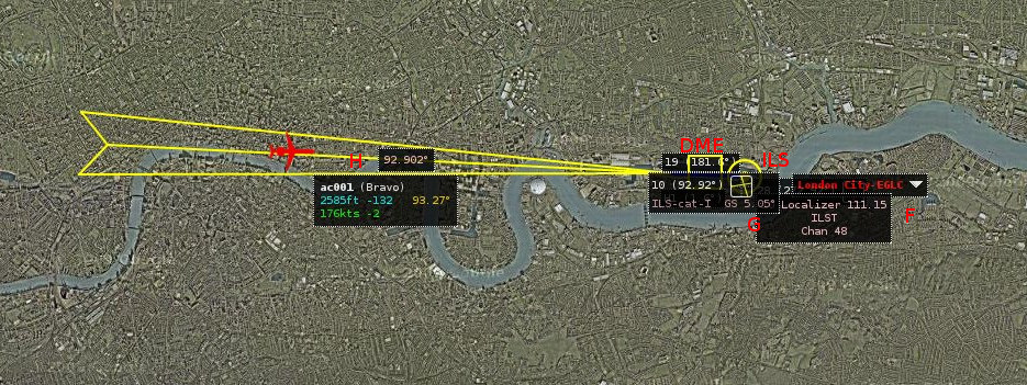
EGLC 10 Runway Map view
- ILS - the array is at the end of RWY 10 indicated by circle
- DME - the transponder is the yellow square, approx half way down the runway.
- F - the ILS frequency 111.15
- G - the glideslope is 5.05 degrees
- H - the runway alignment is 93.27 magnetic
- The large circular building on the South shore is the Millenium Dome
EGLC 10 Cockpit view
Press F11 on the keyboard to bring up the Radio dialog.
- The radio freguency of NAV1 has been set to 111.15
- The course to set to 93 degrees.
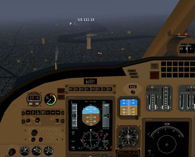
The Millenium Dome is visible behind Canada House just to the right if the approach. Please ignore the smokestack.
Glideslope
- The aircraft is descending through 2540 feet
- The aircraft is already pitching down at 5 degrees
- R on the bottom right of the PFD - the current descent rate is around 1150fpm
- P near the runway threshold - the PAPI lights are visible, and look all white from a distance, means too high.
- G on the PFD - the green dot is below the marker, means the aircraft is above the glideslope.
To correct this position, the aircraft needs to descend vertically faster to capture the glideslope.
Localiser
- L on the both the PFD and the CDI - the aircraft is on a course almost parallel to the runway. The aircraft needs to be positioned to the left of its current course to align with the runway centerline.
To correct this position, a little rudder to steer to the left then right to align with the runway.
Speed
- The aircraft is travelling at around 160 knots which is fast. Speedbrakes would be helpful.
- Pitching the nose down will increase speed.
Distance
- D on the PFD - the green lettering above shows 4.3nm
- D on the DME reciever middle of bottom - shows 04.3nm
- The runway length is 1500m so the threshold is around 4.05nm away
Conclusion
This is probably a missed approach.
- The aircraft is travelling fast and pitching the nose down will increase speed more.
- There is less than 4nm to the threshold.
- The runway is short, so an overrun at speed is likely.
- More speed means more noise and EGLC has strict noise limits (notice proximity of SkyScraper).
Other possible techniques to land such as:
- throttling the engine down and pitching the nose up to reduce speed and therefore height.
- speedbrakes.
- just make a really fast dive landing
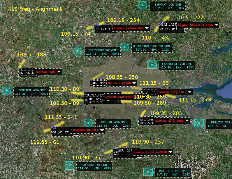
ILS Playground
- Below are the airports in SE England, UK centered on London Heathrow.
- The yellow lines are the ILS beams and are definately not too scale.
- The yellow labels indicate ILS Frequency - Alignment in degrees for entry in NAV1.
- Northolt (just above EGLL) and Benson (leftmost) have ILS on one end of the runway only.
Back Course
Whilst the ILS is a vital aid in landing, the signals and instrument work all the time, including take off. So for the first flight its recommended you tune NAV1 to opposite runway, and climb the glideslope. Aircraft approaching at the same time would not be a good situation. for example: Taking off from
- after takeoff the CDI is show youor drift from the runway center line and the glideslope unusual.
- approaching and crossing the end of the runway is the Zone of Consufion and all the meter's will sump all over the place for a few moments.
- then the readings will get quite accurate to position the aircraft to the readings

