Space Shuttle Navigation
| Space Shuttle |
|---|
| Main article |
| Technical |
| Checklists |
| Nominal Operations |
| Nominal Operations Advanced Tutorials |
| Intact Aborts |
| The other space shuttle |
The navigational needs of the Space Shuttle change substantially during the course of a mission. Once in a stable orbit, the position of the Shuttle at any given time can be predicted fairly accurately by simply solving the equations of orbital motion. This is different in the atmosphere where such predictions are much more involved because atmospheric flight is fairly complicated. Different techniques and different hardware is used for both cases.
State vector
The central concept of Space Shuttle navigation is the state vector of the vehicle. As the name states, it describes the state of the spacecraft at a given instance in time, i.e. it contains a timestamp, the three position coordinates (measured in an inertial coordinate frame), the three velocity vector components and the three attitude angles (yaw, pitch and roll).
Given the state vector, numerical orbital motion prediction can be used to determine the state vector at any future time if there are no forces acting on the Shuttle. Note that for a number of reasons standard Kepler 2-body orbital mechanics is not accurate enough for the purpose - in reality (and in FG) Earth is not a point mass but has a more complicated gravity field.
The numerical computation of the state vector can also be done if forces are acting, but the forces need to be known. Inertial measurement units (IMUs), aboard the Shuttle, based on gyroscopes, sense any acceleration away from an inertial frame. Similarly functioning Rate Gyro Assemblies sense any changes in inertial attitude.
The Space Shuttle Avionics hence knows where the Shuttle is at any time by computing the state vector numerically given orbital mechanics and the sensed forces. That's called the propagated state vector. This procedure is error-prone, because neither are the equations of motion for the numerical prediction perfectly known, nor can they be computed to perfect accuracy, nor can the forces be sensed with perfect accuracy. Over time, the internal state vector known to GNC will therefore deviate from the true state vector. The purpose of the navigation systems is to supply extra sensor information to minimize the drift and to periodically correct the state vector.
Sensor information is always incorporated via Kalman filtering, i.e. GNC estimates a likelihood that any sensor reading is 'real' given the internal state vector and incorporates new data only if it fits into the overall picture. In this way, navigation does not go astray in case of sensor failures. Given a filter, any sensor reading can be characterized by a residual (difference between direct measurement and same quantity computed from the state vector) and a ratio (likelihood of the sensor reading being good given the overall picture).
It's important to note that a small residual does not mean that the propagated state vector is close to reality - it just means that the propagated state vector is close to a sensor reading, but they may both be wrong the same way. In particular, there are state vector update procedures which allow you to replace the propagated by the filtered state vector. After executing such a command, the residuals will always be small, but the state vector will be wrong if the filtered state vector was bad. It's important to understand this and make good judgements.
The basic characteristics of the navigational problem (including error propagation, sensor quality with respect to the propagated state, state vector corrections) are modeled in FG. However, it is possible to switch to perfect navigation in which the propagated state vector equals the true state vector using the simulation options.
In a stable orbit, attitude drift (relevant for e.g. antenna pointing) is usually more important than position drift. For attitude sensing, the Shuttle is equipped with two star trackers, augmented by the Crew Optical Alignment System (COAS). Position updates to the state vector come either from the GPS receivers or from remote-sensing the Shuttle via radar whenever it overflies a ground site and uplinking state vector corrections determined that way.
The star tracker
Hardware
The star tracker system consists of two cameras, a left-pointing (-Y) and and upward pointing (-Z) system. Each of these has about a 10 deg field of view. If the star tracker observes a star within its visual field, it utilizes a list of ~100 bright stars stored in the data base to compare the coordinates in the sky using the current state vector with the coordinates the star should have from the data base. Measuring two stars that way gives an accurate update of the inertial attitude.
However, stars can only be identified by their position, so if the angular difference of internal and true state vector exceeds 1.2 deg, the star tracker can no longer operate - in this case the COAS has to be used to correct attitude.
Part of the orbital arrival procedure is to open the star tracker doors (which need to be closed for de-orbiting) - once that has done, the star tracker is operational.
Usage in FG
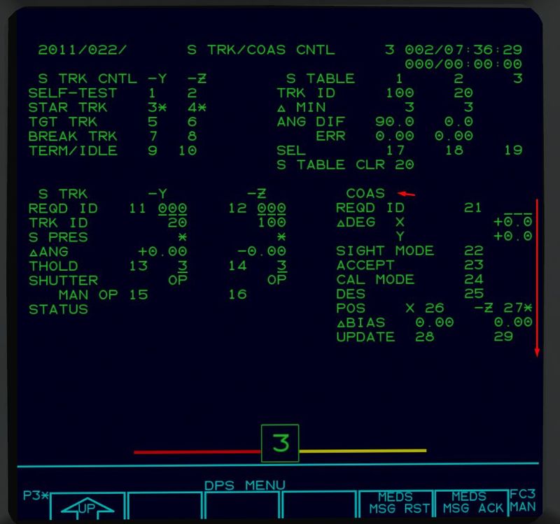
In orbit, the star tracker is controlled via SPEC 22.
During normal operations, items 3 and 4 (STAR TRK) should be selected. Items 5 or 6 allow one camera to be used for proximity operation navigation instead (see there), whereas items 9 and 10 switch the tracker off.
Whether a star is seen by the tracker or not is indicated following S PRES with a '*', the ID of the star is given as TRK ID, the angular correction to the current state vector as ΔANG. The upper right section shows a list of the three latest observations which can be cleared with item 20.
If a star tracker happens to point at the sun, shutters will automatically close to protect the optics, in which case shutter status will change from 'OP' to 'CL'. Whenever the Shuttle maneuvers, the angular motion of the cameras across the sky will be too fast to allow tracking and the status of the trackers will change to 'HI RATE'. If the star trackers go out of alignment and can no longer reliably identify stars, the status will change to 'FALSE TRK'.
Usually the star tracker should require minimal intervention and perform its function fine on its own.
COAS
Hardware
The COAS system consists of a mountable frame which can be applied to the forward (+X) or upward (-Z) windows. Alternatively the HUD can be used. The frame contains an aiming pattern.
The idea is to maneuver the Shuttle such that a known star is in the center of the pattern and then to mark an attitude reference (i.e. the current attitude of the IMUs is stored). By taking two such attitude references and comparing to the stored star database, the inertial attitude correction for the propagaed state vector can be computed.
Usage in FG
The COAS procedure is fully supported, albeit only for a limited number of stars. As of March 2016, no COAS frame is modeled, so the Shuttle has to be aimed at a star using the HUD (and thus COAS marks can only be taken in the +X direction).
Like the star tracker, COAS operations are controlled from SPEC 22.
To use the COAS, wait for the night portion of the orbit till the stars come out. You need some knowledge of the night sky to identify constellations and find the star you need. Pick one of the stars from the supported table and enter its index as item 21.
| index | star |
| 11 | Shedir |
| 12 | Mirphak |
| 13 | Mizar |
| 14 | Arcturus |
| 15 | Betelgeuse |
| 16 | Procyon |
| 17 | Spica |
Make sure the COAS position forward (item 26) is selected. Point the Shuttle at the chosen star. When it is centered, press Ctrl+A to take an attitude reference. If you feel it wasn't good, you can take more, the last will overwrite all previous ones. Once you think the reference is good, accept it by executing item 23. Enter the next star ID via item 21 (ideally make sure they're about 90 degrees separate). Take another attitude reference, and once you're happy, accept with item 23.
You'll now get to see ΔBIAS values which tell you how much your just determined attitude deviates from the state vector. If you pointed at the wrong star, expect the biases to be very large. If you're just outside the star tracker operating range, a bias of 40 deg is probably not real.
If you are convinced that the COAS is okay, execute item 28 to update the state vector. If you want to start from scratch, execute item 20 which clears the star table and all COAS references. Usually, the star tracker should be back in working condition after a COAS procedure.
GPS
The Space Shuttle is able to receive position information from the GPS network via on-board GPS receivers. Currently, the GPS operation for the Shuttle is not very accurately modeled, GPS is assumed to be an 'always on' device characterized by a constant figure of merit, which is then used to limit the position and velocity errors in the propagated state vector.
The point of area navigation is to guide the Shuttle accurately through the final entry phase and terminal area energy management (TAEM) onto the runway.
During the high thermal load phase of atmospheric entry, the Shuttle is enclosed by a plasma sheath which blocks all communications, i.e. neither state vector uplinks, nor GPS information nor any radio beacon is available, and it is impossible to deploy air sensors into the hot plasma. During this phase, only altitude can be sensed as drag altitude by using a model to relate deceleration forces sensed by the IMU to atmosphere density given the propagated state vector.
Area navigation starts after the high load phase, with first GPS information becoming available after the communications blackout. At Mach 5, the air data probes can be deployed which supply measured Mach number, AoA and pressure altitude. About 400 miles to landing site, the TACAN receivers start to pick up the radio beacon signal, and during the final approach phase, the Microwave Landing System (MLS) provides glideslope information.
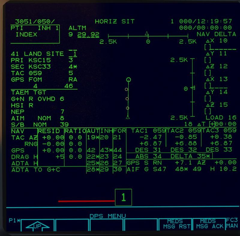
Most of the area navigation information is summarized on SPEC 50:
The landing site is selected as part of the de-orbit preparation via item 41. Since the Shuttle has rather special navigation requirements, it does not use the normal FG-wide net of radio beacons but special definitions, i.e. like in the real Shuttle, area navigation is only available for a number of selected sites. Currently valid landing sites (including transatlantic abort landing (TAL) sites) with their index are
| index | site | status |
| 1 | Kennedy Space Center | regular |
| 2 | Vandenberg Air Force Base | regular |
| 3 | Edwards Air Force Base | regular |
| 4 | White Sands Space Harbor | regular, lakebed landing |
| 5 | Zaragoza Airport | TAL |
| 6 | RAF Fairford | TAL, currently no TAEM guidance |
| 7 | Banjul International Airport | TAL |
Dev version December 2020 list
1 Kennedy Space Center regular
2 Vandenberg Air Force Base planned regular
3 Edwards Air Force Base regular
4 White Sands Space Harbour regular, lakebed
5 Zaragoza Airbase TAL
6 RAF Fairford TAL
7 Banjul International Airport TAL
8 Moron Airbase TAL
9 Le Tube TAL
11 Bermuda Intl. emergency site
12 Halifax emergency site
13 Wilmington emergency site
14 Atlantic City emergency site
15 Myrtle Beach emergency site
16 Gander emergency site
17 Pease emergency site
30 Easter Island TAL
32 Diego Garcia emergency site
33 Honolulu Intl. emergency site
34 Keflavik Airbase emergency site
35 Andersen Airbase Guam emergency site
Once the site is selected, items 2 and 3 show the available primary and secondary runway choice (and executing the item allows to change the choice). Item 5 shows the associated TACAN channel (which can currently not be changed).
Items 6 and 7 allow to select the intended TAEM pattern from OVHD (overhead) to STRT (straight-in) and to change the aim point from nominal (NEP) to minimal (MEP). Both options should only be used if the Shuttle is low on energy at TAEM interface, for a detailed explanation refer to the crew manual.
The lower portion of the display summarizes the area navigation data sources and their fit into the current Kalman filter, i.e. TACAN azimuth and range, drag altitude and air data altitude and GPS information. The right lower part shows the direct output of the TACAN receivers as azimuth and range where items 34 and 35 can be used to switch from relative to absolute azimuth. TACAN azimuth can be flown after entry guidance ΔAZ is no longer displayed after passing the TAEM interface and before the graphical portion of the display shows the heading alignment cone (HAC).
For the air data altitude, QNH at landing site can be adjusted with item 9. Faulty TACAN receivers can be deselected with items 31-33.
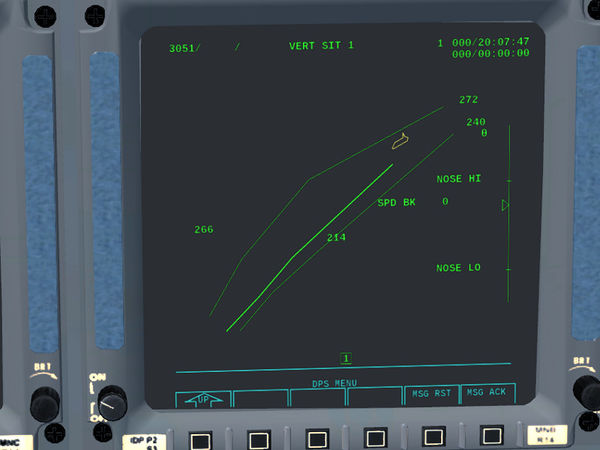
Once some 30-40 miles to range, the graphical center portion of the display shows touchdown point, final approach line and HAC as determined by the current state vector. A corresponding picture of the desired altitude dependent on remaining range is supplied by OPS 305 (VERT SIT) which should be used together with SPEC 50 during TAEM.
Staying on the central trajectory vertically and aiming the trajectory predictors around the HAC horizontally leads the Shuttle right into a good final approach.
Note that the vertical display always assumes that the Shuttle flies the nominal horizontal groundtrack. Once you deviate from the HAC, vertical information is no longer reliable.
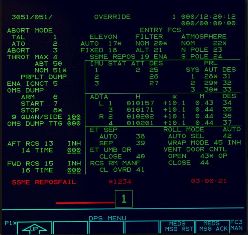
In addition, if so desired, the raw data coming from the air data probes (once deployed) is available on SPEC 51 as ADTA roughly in the center of the right column. Faulty air data can be deselected using items 34 to 37 here to be prevented from being used for the state vector.


