Flying the Shuttle - Transoceanic Abort Landing TAL
| Space Shuttle |
|---|
| Main article |
| Technical |
| Checklists |
| Nominal Operations |
| Nominal Operations Advanced Tutorials |
| Intact Aborts |
| The other space shuttle |
(Written for the devel version of October. 2018 https://sourceforge.net/p/fgspaceshuttledev/code/ci/development/tree/)
Let's talk about another very interesting Intact Abort, the Transoceanic Abort Landing.
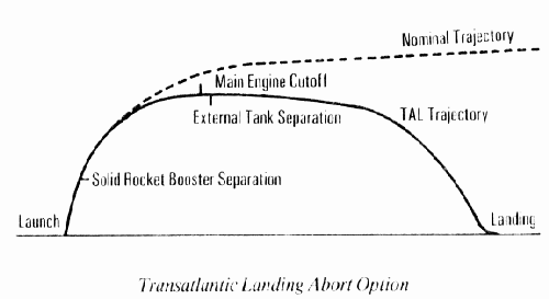
Quite fascinating one, we will cross the Atlantic and land 30 mn after liftoff on the other side of the Ocean in Spain, Zaragoza.
Roughly 2 mn into the flight, Window for TAL opens in case of a single engine failure. Not enough energy to reach an Orbit, but enough to land somewhere in Europe.
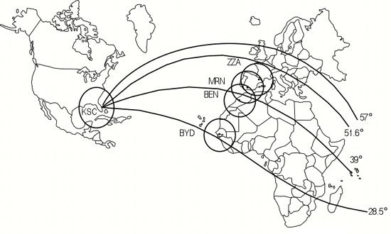
Different Ground Track and different TAL site depending on the Launch Azimuth and Inclination targeted ( 51 ° for us, a Launch to ISS )
Official document about Intact Abort to learn more about it, a must read and small one.
https://www.nasa.gov/centers/johnson/pdf/383447main_intact_ascent_aborts_workbook_21002.pdf
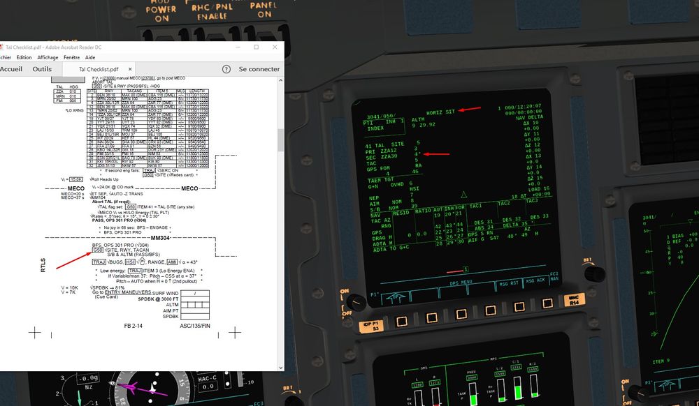
Also, you can find by following the next link some Checklist that we will use once the failure happened and the Abort is engaged.
This checklist allow us to have an easy access to the Pre/Post MECO actions to do.
Also, the guidelines for entry are included, so no need to switch between differents documents.
Launch will occur in KSC, Florida. Liftoff with a North East azimuth to reach ISS inclination orbit of 50°.
That will allow us to stay in a realistic frame data and checklist wise. Checks we are going to use are those from STS 135, last Shuttle flight to the ISS with Zaragoza as primary TAL airfield.
Zaragoza is the preferred TAL site for inclination around 50° due to the low cross range , and the very long runway available.
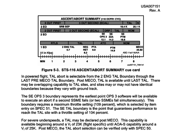
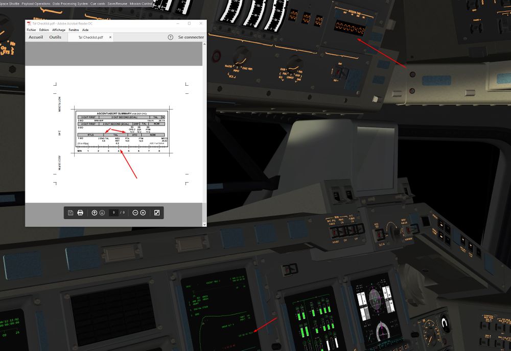
A sum up of the different boundaries for Intact Abort ( last line for one engine out) coming from STS 116 ( almost the same for us)
Failure will be introduce at 4 mn, just after the Negative Return where the RTLS is now impossible. Moreover, at 4 mn we are In the middle of the TAL window. That gives us a safety margin towards high energy TAL ( late TAL engagement ) where is tougher to manage a safety return to a TAL site.
Start Flightgear with the commandline options
--aircraft=SpaceShuttle-launch --lat=28.6206 --lon=-80.6133 --heading=270 --timeofday=morning
From Lift off to MECO
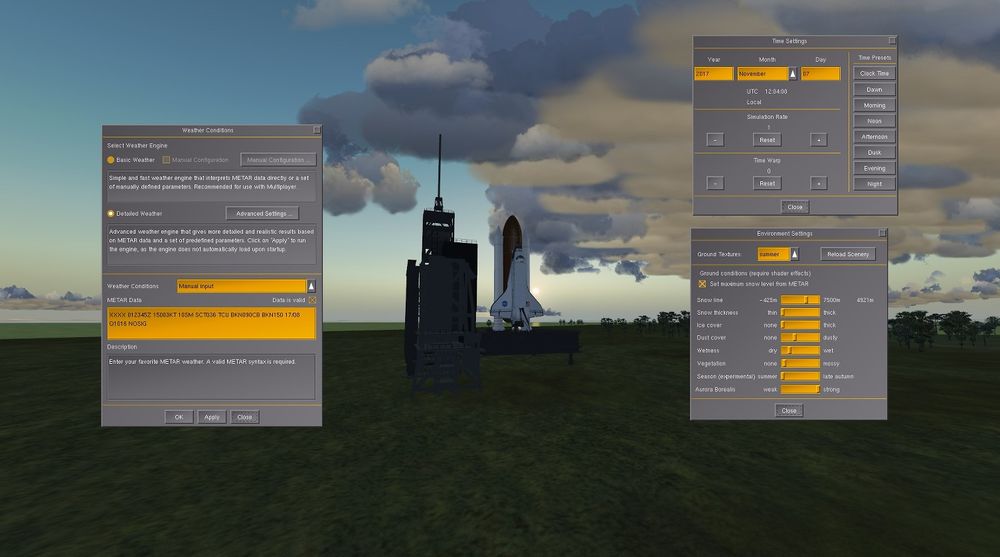
1)We start at the KSC, early summer morning Here are my settings for the weather I chose for that Launch. Nice weather, broken clouds and light winds. GO for launch.
A bit of cockpit preparation.
We select the correct launch azimuth in the launch autopilot to reach a 50 ° inclination.
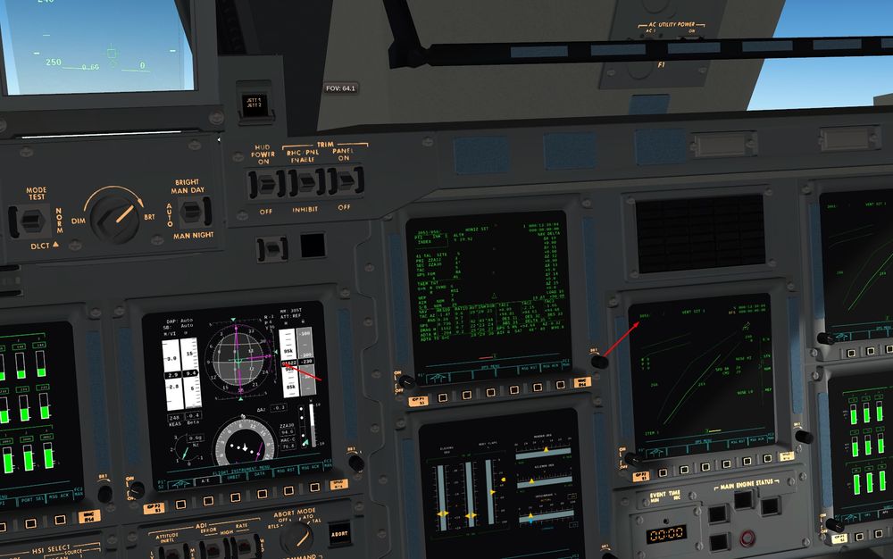
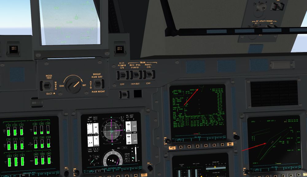
In SPEC 50 , we select ZZA as the TAL airfield TAL ITEM 41 +5
We configure also correctly the cockpit layout ( BFS on CRT 3)
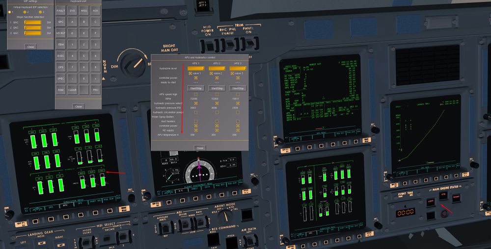
Start Up of the APUs
2)T-6 secondes, ignition of the 3 SSME Shift+i
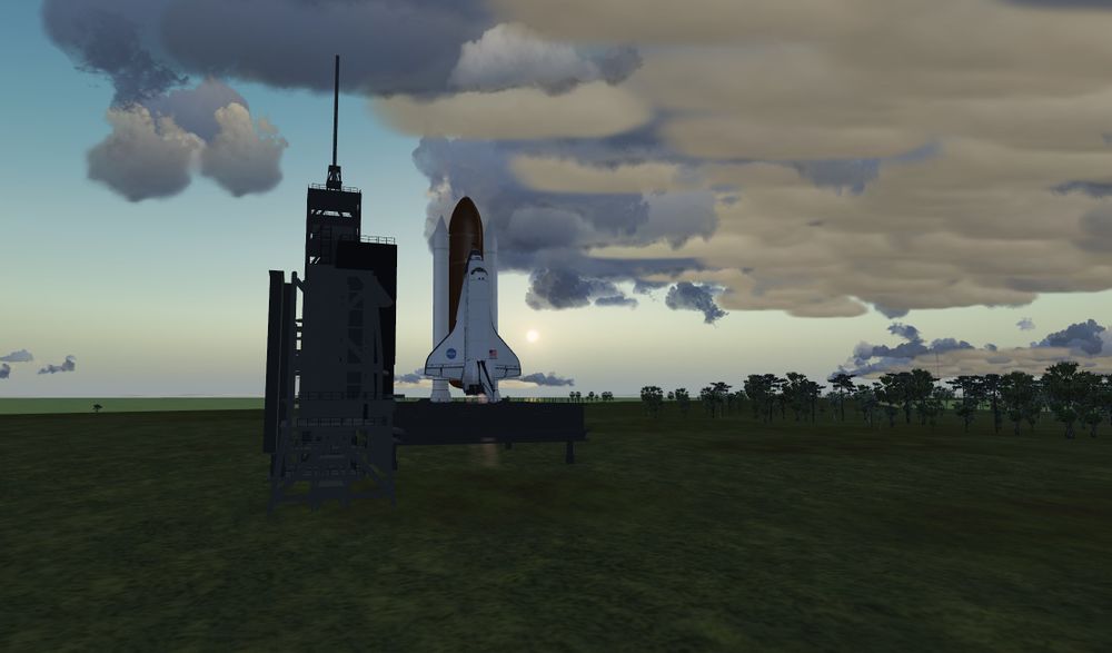
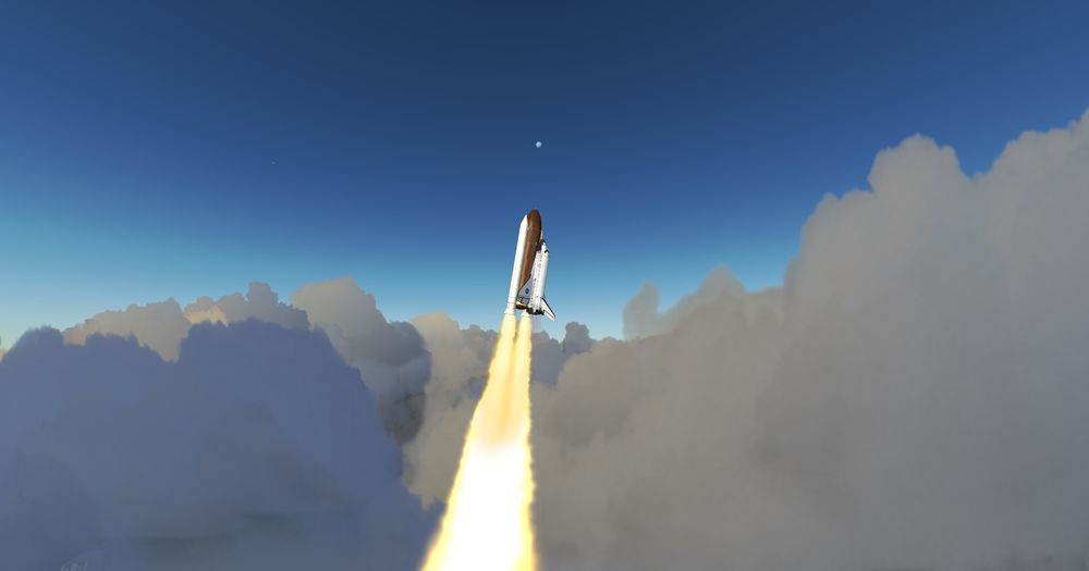
And Liftoff, tower is cleared , the Shuttle can roll to take the correct launch azimuth if you chose Heading 90 in the Launcher Config ( Tail facing the Sea like in Real )
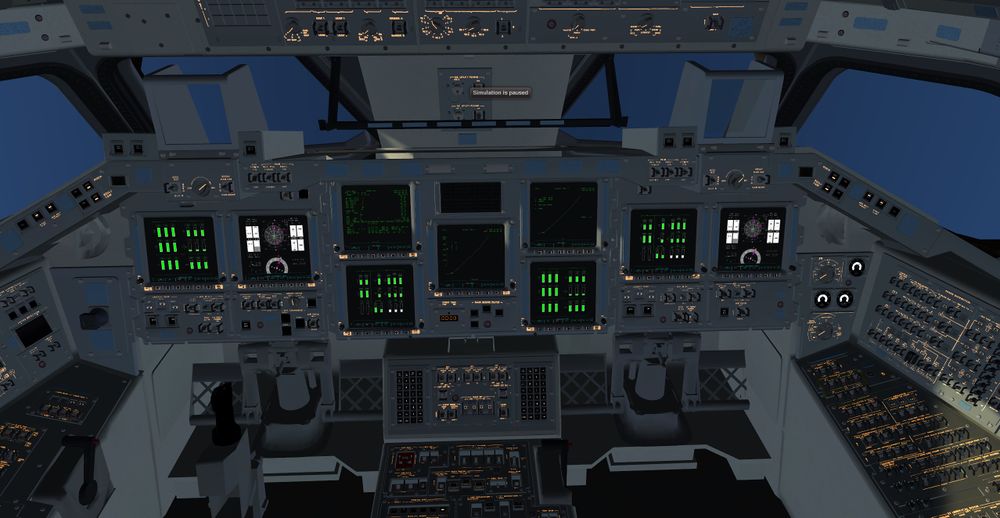
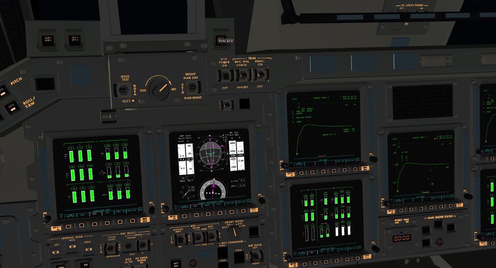
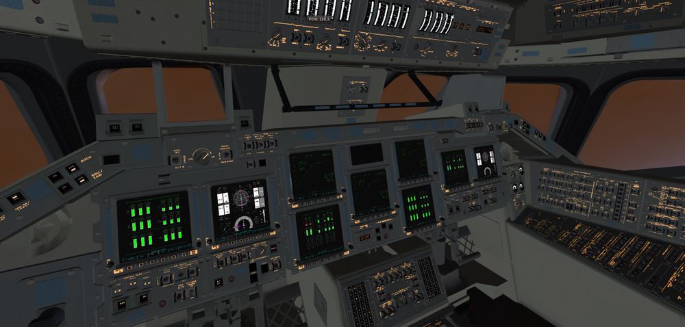
Cockpit view from the Mission Specialist seat , impressive and complex
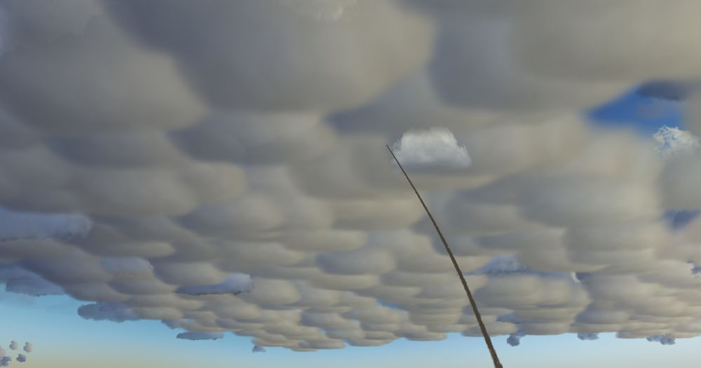
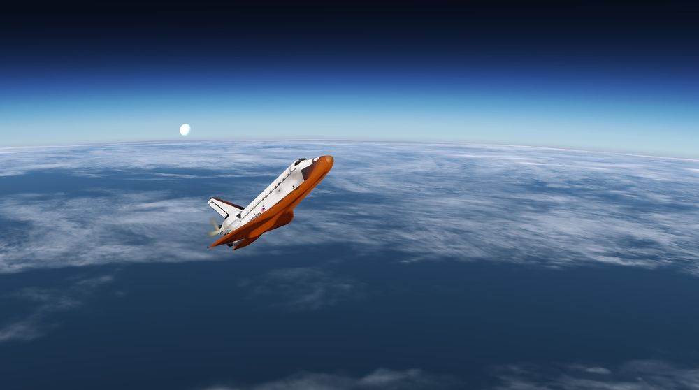
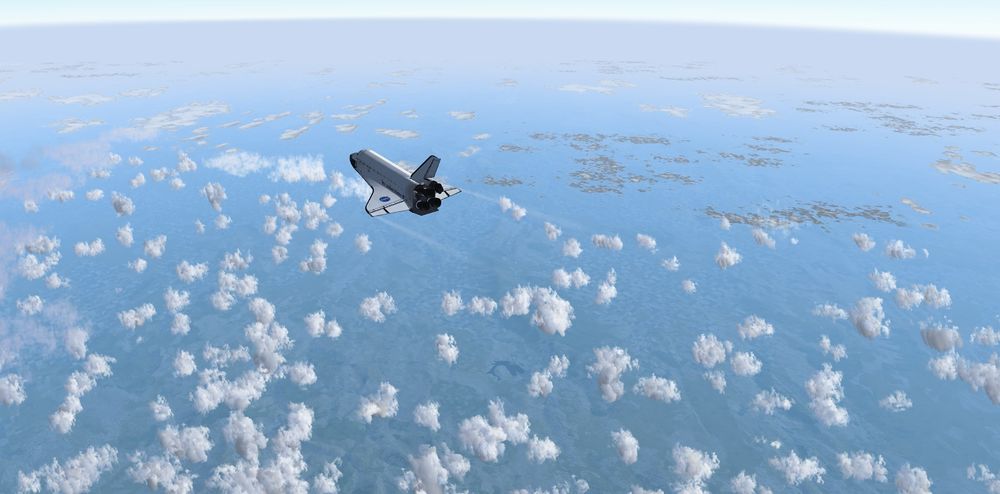
Nice view of Cumulus and the Moon behind.
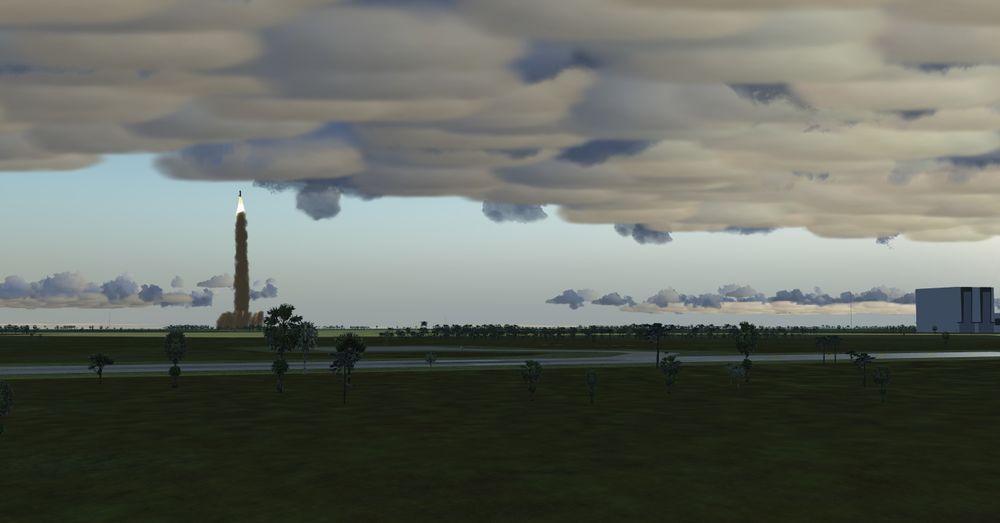
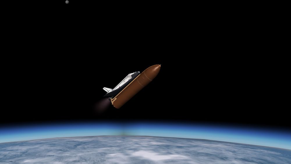
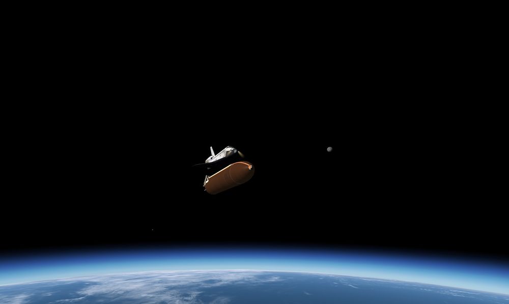
Farewell Atlantis , see you soon.
3) 2 mn, SRB separation and we move towards OPS103 , or Second Stage Ascent Phase
Everything is looking good so far
But of course, it will degrade soon. We introduce the failure on one of the SSME at 4 mn, around Mach 8.
Right in the middle of TAL boundaries.
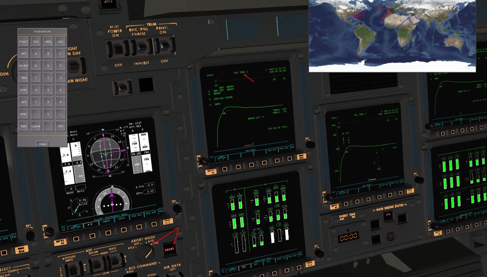
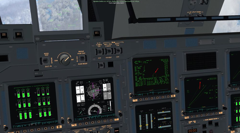
4)Without losing time, the Commander activates the TAL abort switch to have the TAL guidance available.
Shuttle will now be guided laterally to stay close to ZZA ground track and vertically to avoid a too steep re entry angle after MECO.
One of the first thing to do is the OMS tanks dump to avoid to have an afterward center of gravity during entry phase ( leading to loss of control )
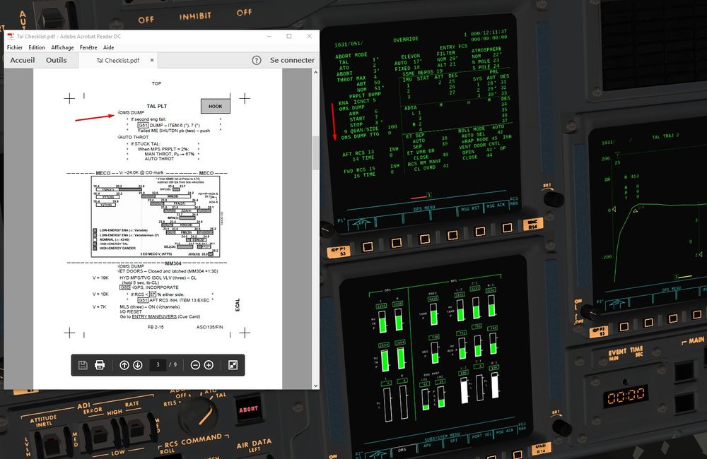
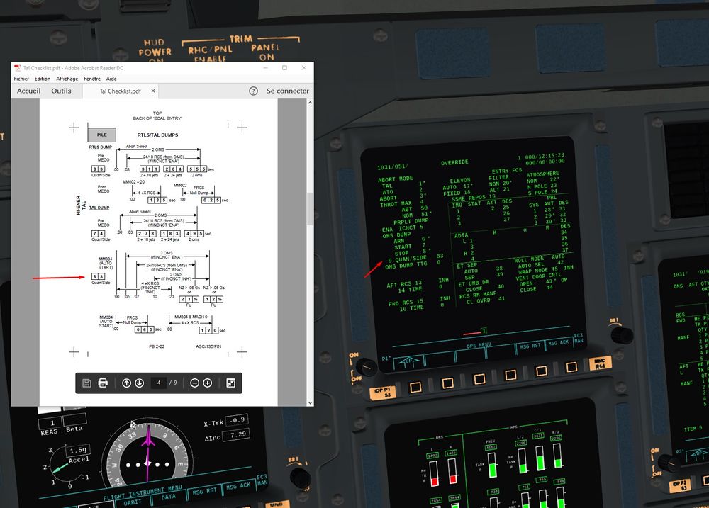
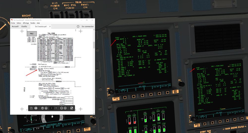
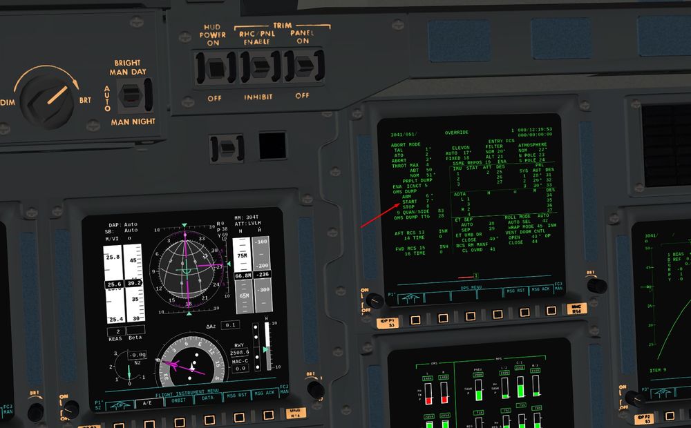
In real, those dumps happen automatically. Quantities are Mission specific i-loaded, depending of inclination, payload, CoG,… For us, it's gonna be done manually using the Override page SPEC 51
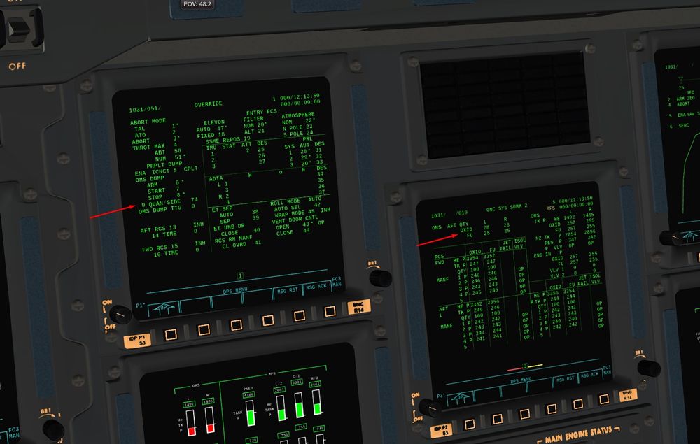
We can either dump everything in one dump ( QUAN/SIDE 100 item 9), or do several dumps by selecting the percentage of propellant to be dumped.
The choice is up to you. Do one dump ( by default quantity to dump is at 100%) or do several dumps like in reality.
I chose the second option for sake of realism, but first one is perfectly viable to do a successful TAL in the simulation ( and would have been even alright in real)
Why several dumps?
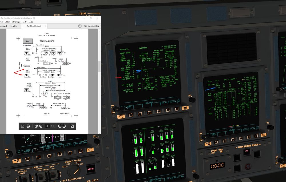
Well, a Pre MECO Dump that we are going to do now ( a dump of about 75% of the total propellant of OMS Tanks)
And a Post MECO dump that we are going to do after MECO, once we transition with OPS304 ( entry software)
This one will dump 83 % of the 25% of propellant remaining in OMS tanks .
Aim here is to add around 100ft/s of speed after MECO to ensure good separation with external tank and avoid re contact.
Very smart, isn't it ?
Also, at the bottom of the check you can find FRCS ( forward RCS) which corresponds to a dump in the forward RCS for a duration of 60 s ( item 15 and 16 )
Same for X RCS ( rear RCS translation on X axis item 13 and 14 )
These two dumps were really Mission dependant, and were used for CoG fine tuning.
We will not need them, as our CoG will be already well within the safety limits.
Let's come back to our Pre MECO dump. We choose the quantity (74%) Item 9+74
We arm, and start it
Item 6 Item 7
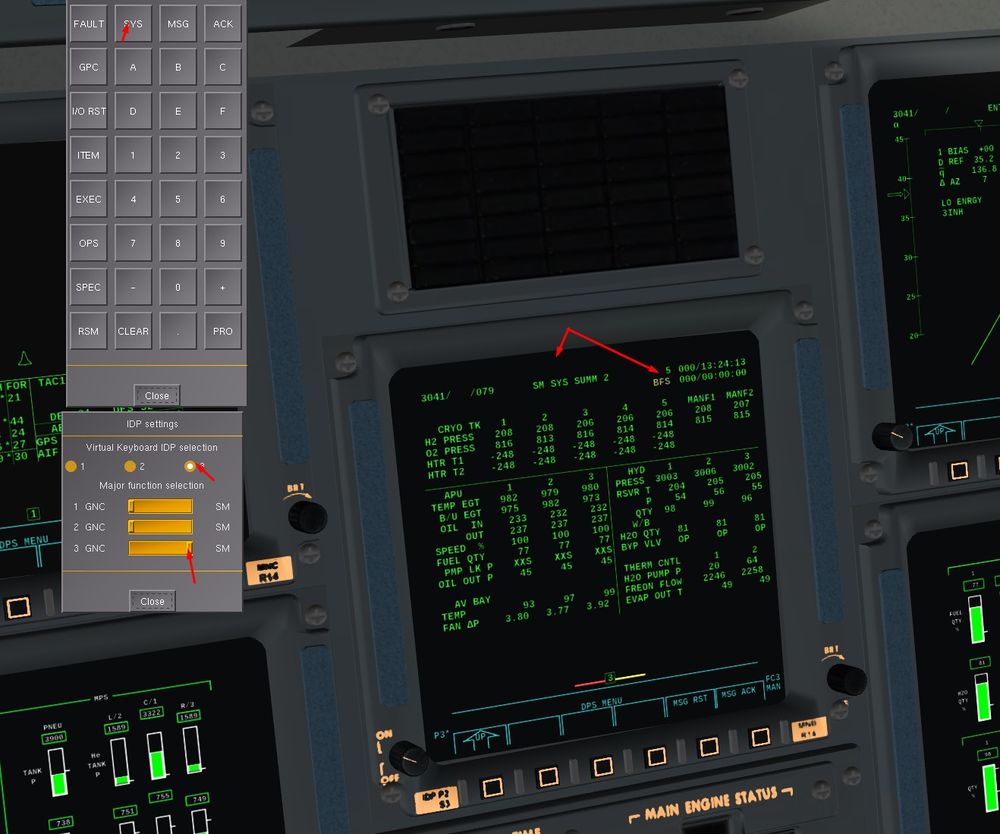
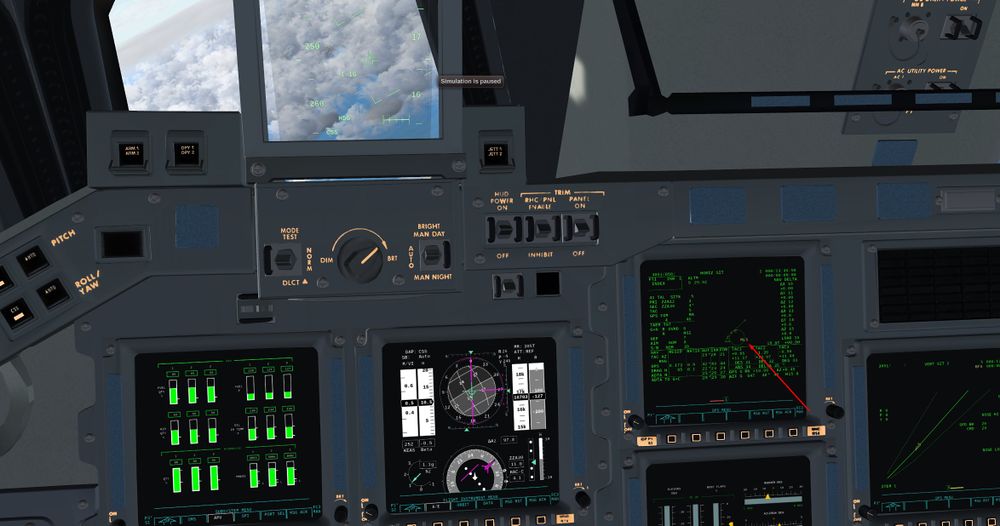
Have a look to the OMS burning, and you can monitor the decreasing propellant quantity on BFS GNC SYS page 2
Another impressive system is the automatic re-organisation of RCS and OMS valves to allow the dump.
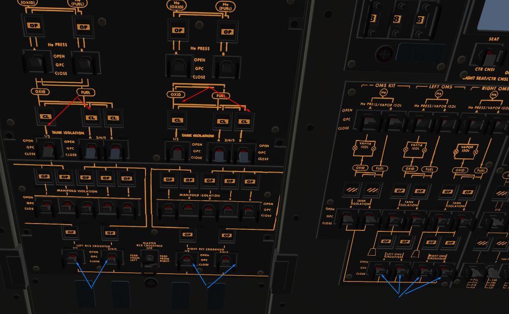
Cross Feed will open and RCS tank isolation valves will close. It allows to dump only the OMS propellant through RCS without using RCS propellant
Awesome.
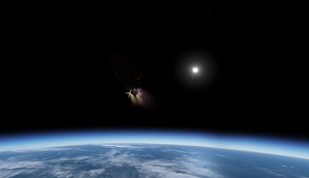
Nice visual
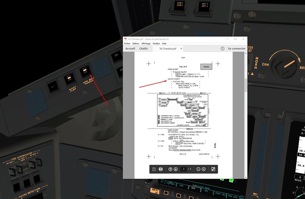
We check that Thrust control is in Auto mode
End of the Pre MECO dump, around 25% of propellant remaining as forecasted.
We can already prepare the data for the post MECO dump which will occur wi the OPS3 transition later after ET separation.
We enter the value of propellant to be dumped, it will be now 83 %
Item 9+ 83
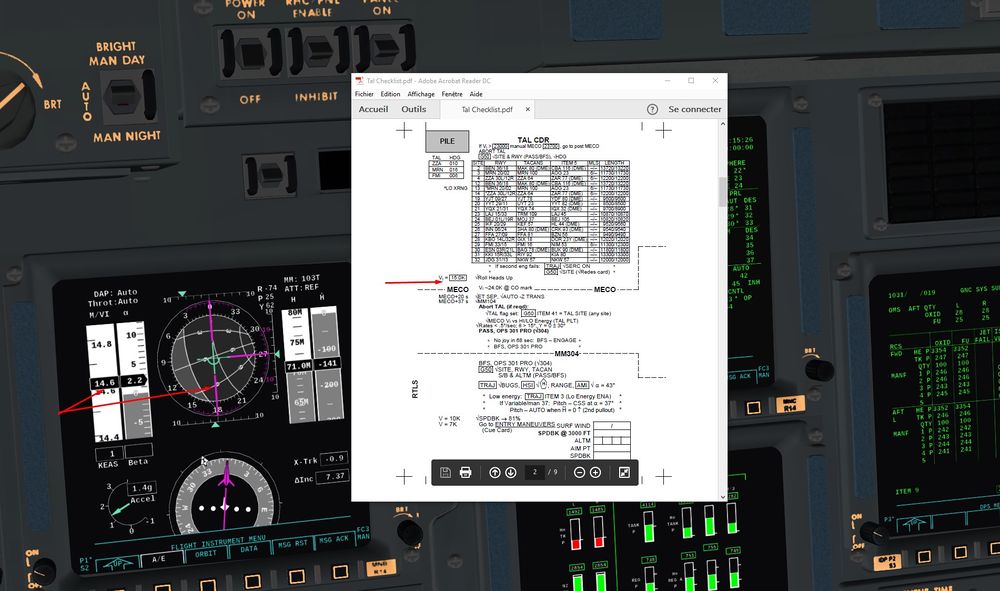
5)Mach 15, we check that the Shuttle performs the Roll To Heads Up ( RTHU), mainly to have a better way of communication with MCC through TDRS satellites.
And MECO is approaching. Mach 25, on our way to ZZA, our ground track is perfectly aligned with it. Good.
From MECO to Entry Interface
Between MECO and the entry interface, there is a lot to do in 2 mn. Don't hesitate de use the pause and to play with time compression
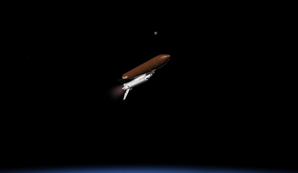
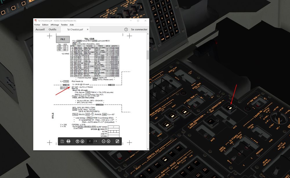
1) We check that 20 seconds after MECO, the ET is well separated from the Orbiter
40 seconds after MECO, automatic transition should occur to MM 104 Major Mode
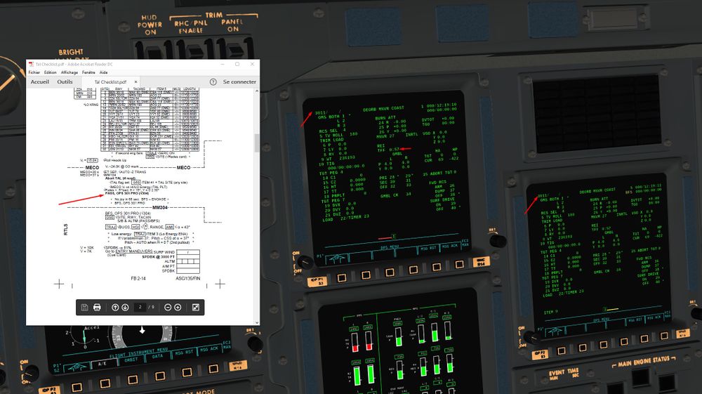
2) we switch manually in OPS 301, Entry Software
TFF (Time to Free Fall 400 kFeet) is very low, Entry Interface is approaching quickly. Let's hurry up.
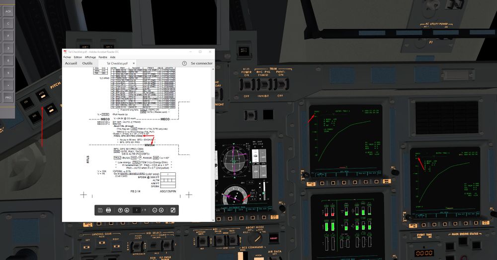
Shortly after, we transition to OPS 304.
We check that we are in Auto Pitch/Roll Yaw
Have a look to the distance to ZZA, 2500 Nm instead of 4000 for a normal entry path.
In consequence, we will have a steeper re entry angle ( higher than nominal vertical speed at EI)
It's gonna heat hard during the first minutes to catch the path.
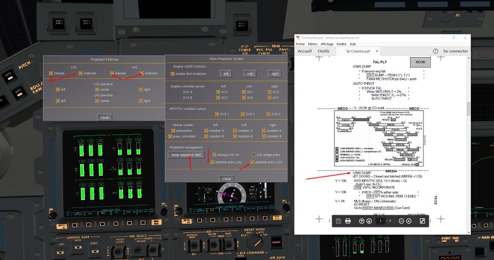
3) we start the LOX and LH2 dump, propellants remaining in engines and feeding lines/valves.
Our center of gravity will move forward, mandatory for Orbiter stability during Entry.
We the latest version, Dump is now done automatically like in reality.
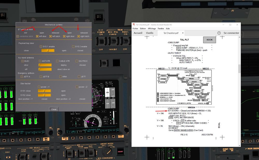
4) We close the Umbilical Doors to avoid Over Heating and mechanical stress during Entry.
If not, the thin layer of aluminium will be quickly burnt during entry, and .. no joy.
Non mandatory phase, more educational part. You can disregard that part if you done a 100% Dump Pre Meco earlier on.
We are going to do the Post MECO dump that we talked about before.
SPEC 51 Item 6 and 7
Normally, with the latest Shuttle Version, the OMS have now Thrust Vector Control ( TVC) after MECO for Dump
That means Shuttle will not Pitch Up during the dump and start rotating due to the upward position of OMS nozzles
However, if you encounter that behavior with your version, next italic advice is for you :
It's better to be in CSS instead of AUTO for that dump. This dump leads to a slight rotation around the Y axis ( pitch up). It's due to the lack of Thrust Vectoring Control of the OMS pods that don't counter act the RCS thrusting, hence a slight momentum in pitch.
Once done, go again in AUTO and the Autopilot should stabilize this slight pitch movement.
After some tests, I found it was better to reduce the duration of that dumps to avoid too much pitch up.
Just a bit of dump to have enough Extra speed to avoid External Tank recontact.
So, Item 9 +43 ( 15 seconds of dump instead of 30 s)
It is more for an educational purpose. Always nice to see what was really done in real, and why.
Now you have the answer to why so many dump and not just one.
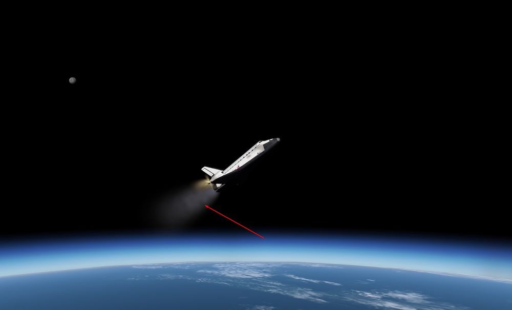
Nice visual on the dump ( LOX/LH2 dump and OMS)
5)we check on SPEC 50 that we have all the correct informations for the TAEM phase later on.
We will take Runway 30 instead of 12
Item 4
It will allow us to do a downwind and to perform a full HAC, much better to handle high or low energy situations that can build up later ( high energy, extend the downwind,low energy straight in available )
OMS dump finished, less than 5% in OMS tanks, perfect for the CoG
Entry
Finally, we have reached the Entry Interface.
We can use the Entry checks ( at the end of the Checks we were using)
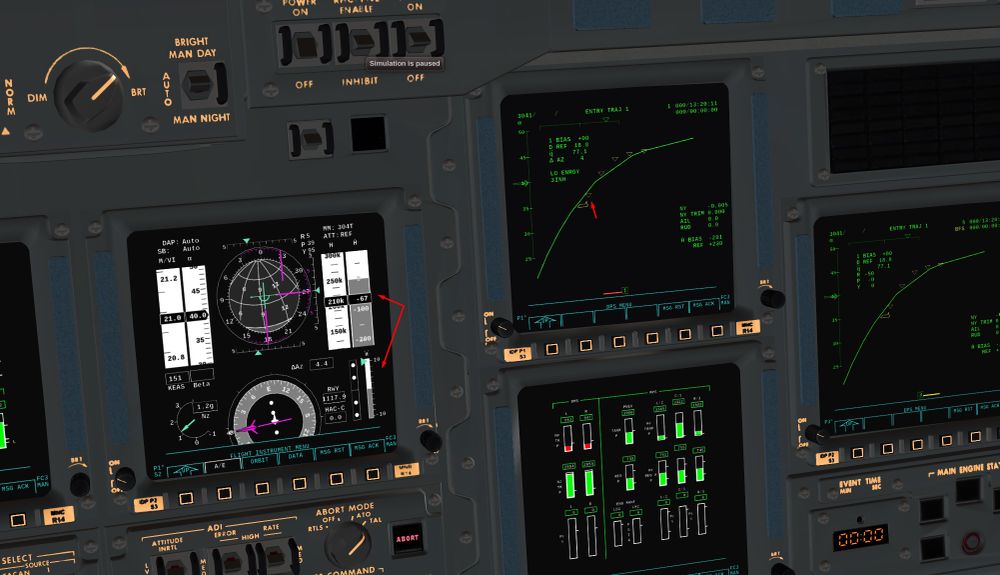
As forecasted, we are high and we are quickly diving into atmosphere.
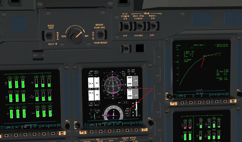
Aim here is to smoothen the fall with zero bank to have a maximum of lift generated by the wings.Hence, the vertical speed will decrease and reach acceptable value.
Lift is increasing, and Vertical Speed is decreasing, good.
Heavy breathing in the cockpit.
Hot, hot, very hot.
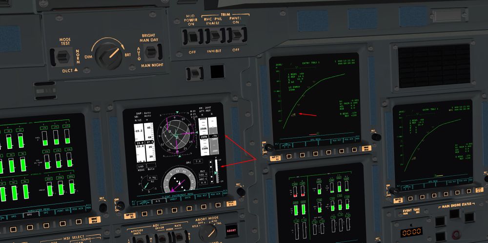
And we have now what we call a phugoid.
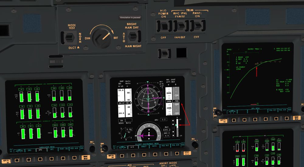
Too much lift generated, VS is becoming positive , and Orbiter is going up and down.
We are coming back on the path, we have to be careful now to not climb too high and to control the VS through the bank angle.
Let's begin Roll Reversal to not climb again. By banking the Shuttle, Lift in the vertical plan will decrease, which will allow us to follow a normal entry path from now on.
It's called H dot capture. Once the correct Vertical speed is established, we cancel the vertical acceleration by banking to find the equilibrium point between drag, lift and weight.
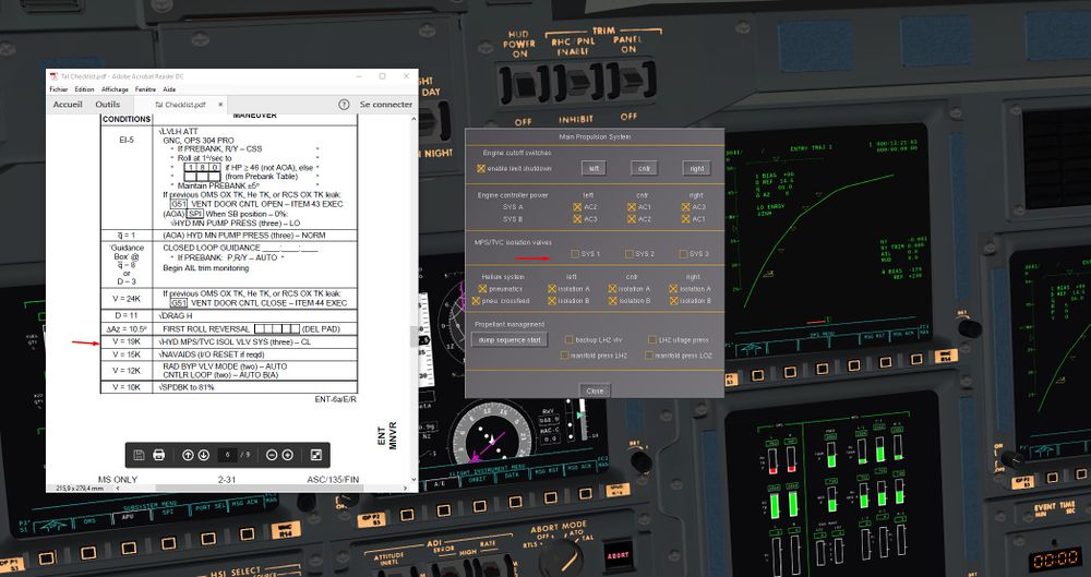
Mach 19, we close the Hydraulic valves from the Main Propulsion System to avoid hazardous movements of the nozzles once on the ground.
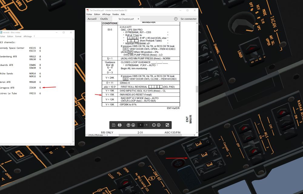
Mach 15, we check Navaids.
MLS channels tuned on channel 6 for Runway 30 at ZZA
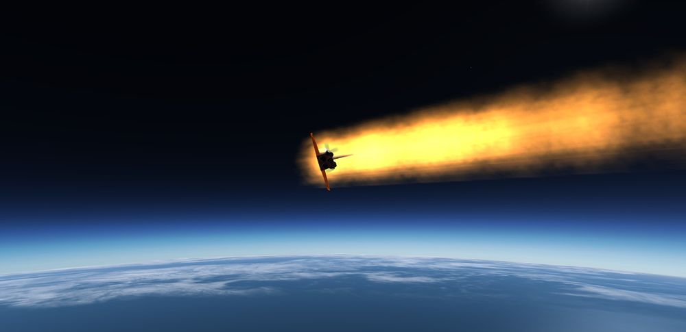
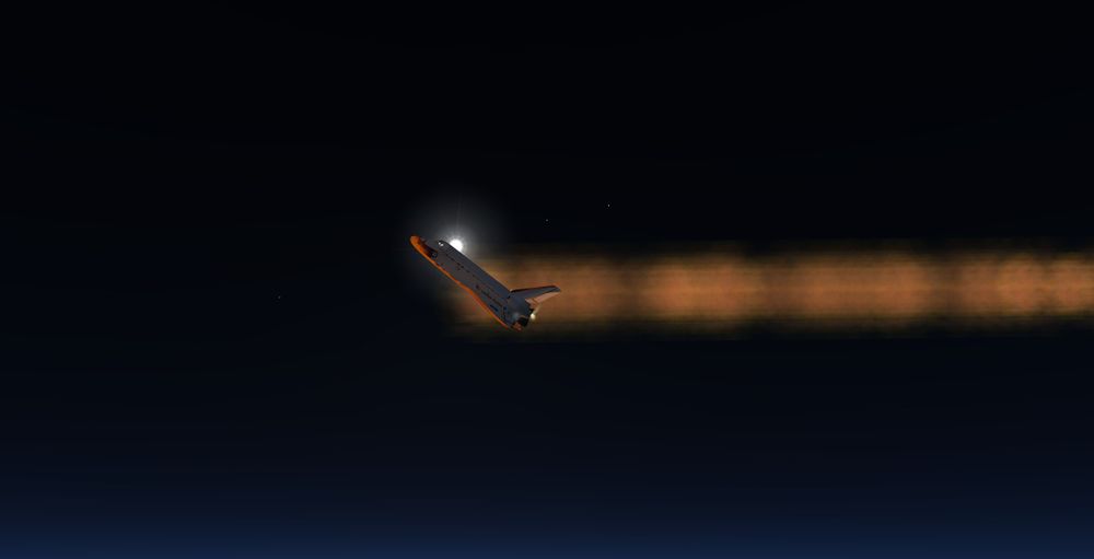
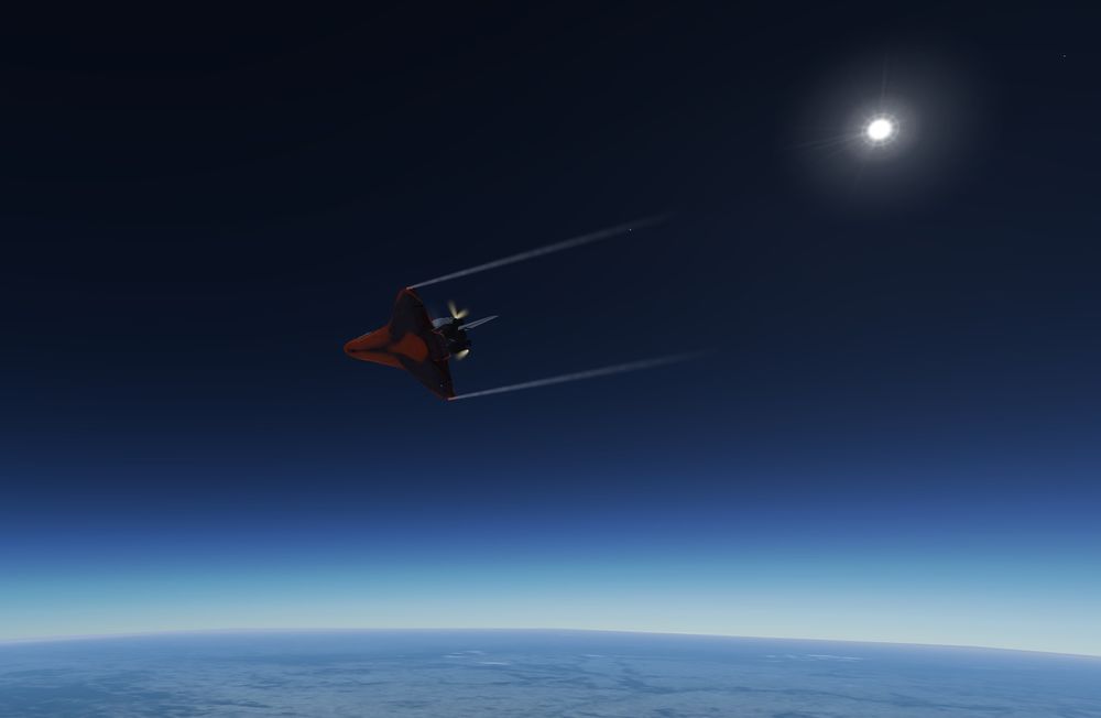
Nice view on the plasma glowing with the Sun backward.
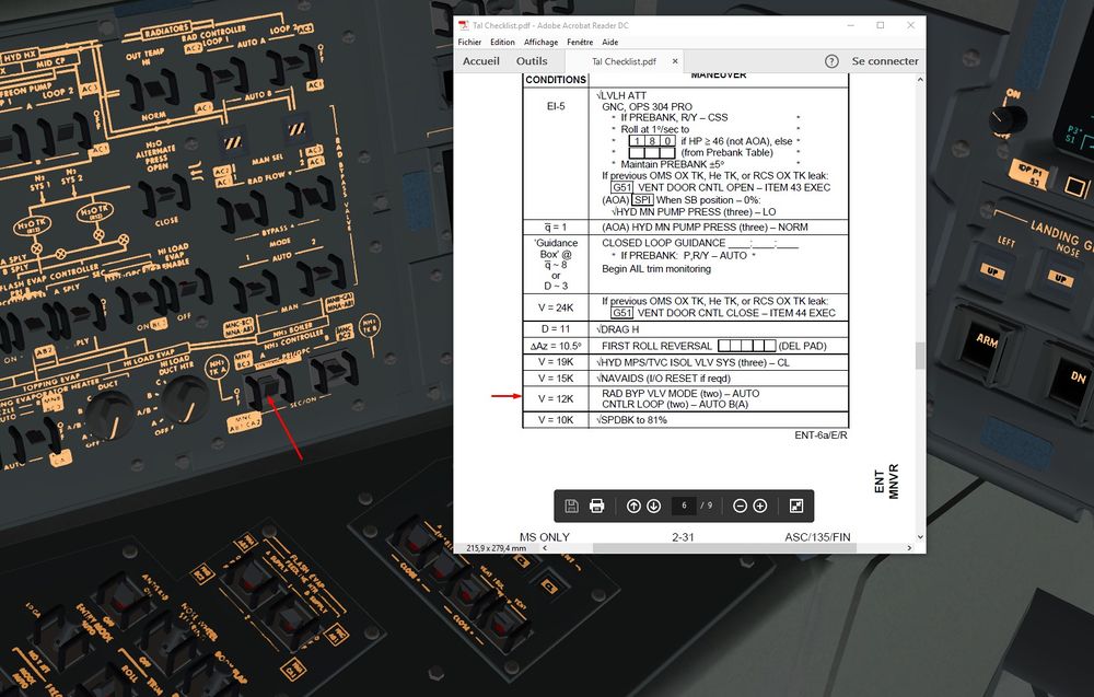
Mach 12, we switch on the Ammoniac Boilers. It will cool down the Freon below 100 kft where Flash Evap are inefficient . Hot Freon will be cooled by Liquid Ammoniac that will vaporize and will be ejected into atmosphere. ( Ammoniac boils at Low Temperature (-33 °C), very interesting for Thermal Management.
We can check Freon Temperature on BFS in SM major function and SYS 2 page ( two click on SYS)
Check that the value of Evap Out starts to rise when below 150 kft and will stabilize around 50° F once NH3 boilers are activated.
EVAP OUT is the parameter to look at.
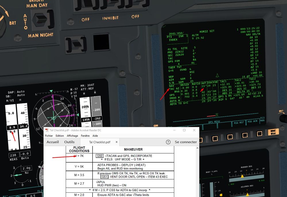
Mach 7, incorporation of TACAN into Navigation filters.
Once the ratio ( less than 1) and residual are good, we can incorporate them to tweak the state vector.
Item 19
Ground in sight Captain.
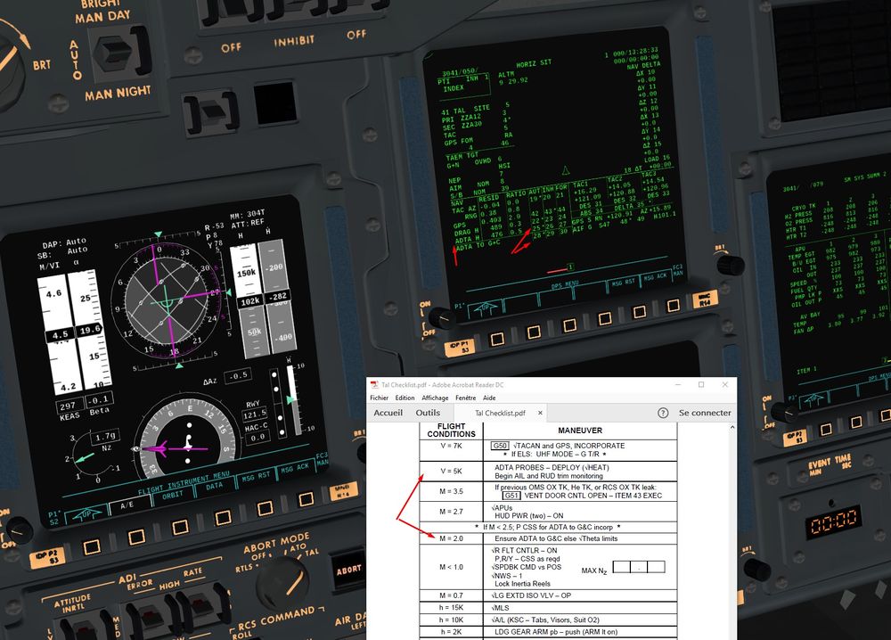
Mach 5, Probes are deployed and once data are good (ratio, residual and Spec 51 ADTA value cross checked with primary flight display one), we can incorporate Altitude into nav filters and other values (Angle of Attack, Mach, Vertical Speed) into guidance and control software.
Item 25 and 28
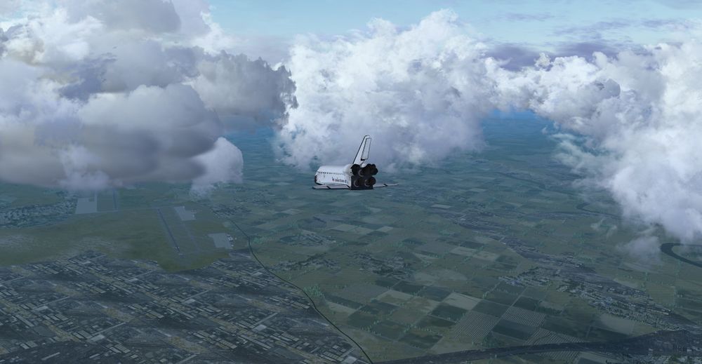
Zaragoza in sight, TAEM interface reached, let's start the gliding part.
TAEM and Landing
For more information on that part of flight, you can go here : Flying the Shuttle - Entry and there Flying the Shuttle - Entry TAEM and Landing Advanced
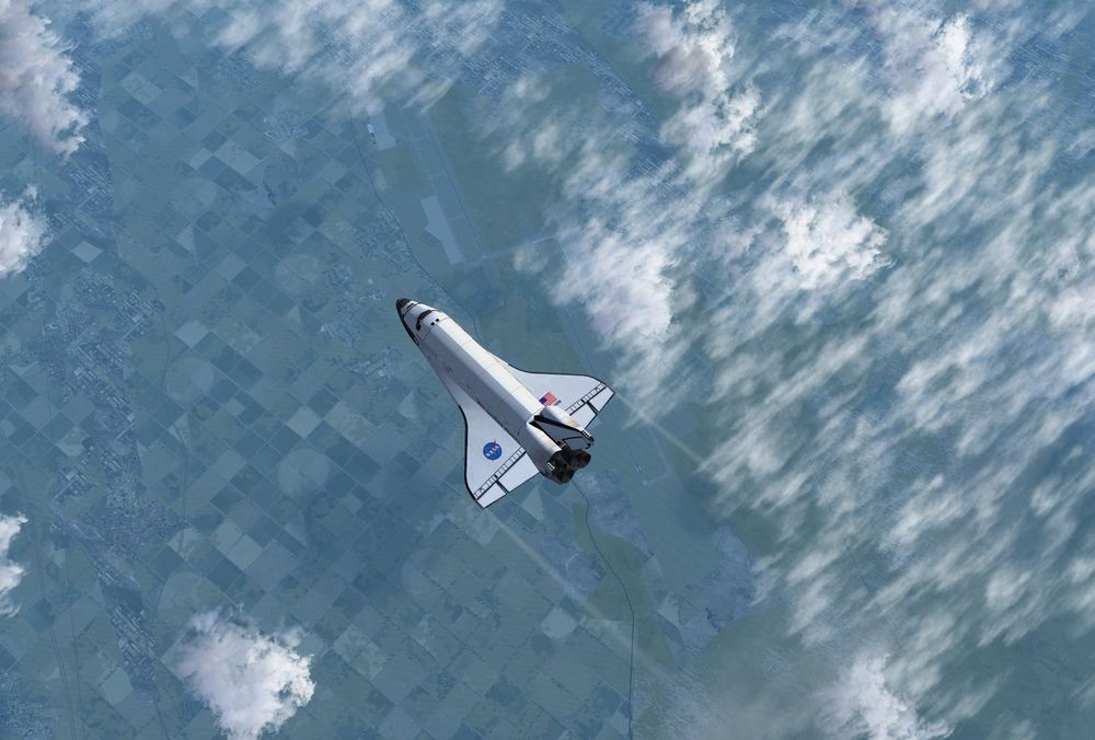
Nice overview of Cervantes Land.
HAC in sight, on track and path. You can take manual control of the beast when you want, but not later than Mach 1.
Overhead the military base, dual Runway. For us, it will be the 30 Right, military one.
Subsonic transition and condensation seen from the tower, BOOM.
Entry into the HAC, a big 180° with a nice bank ( look at the G’s taken, up to 2 G's with 60 ° of bank in level flight )
Last turn
Around 15000 feet, we check that the MLS are activated ( yellow MLS). I will give us a very fine tunning of our State Vector.
Long final, 7 Nm at 12000 feet, and a 20° glidepath
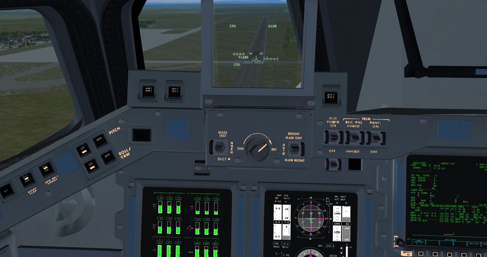
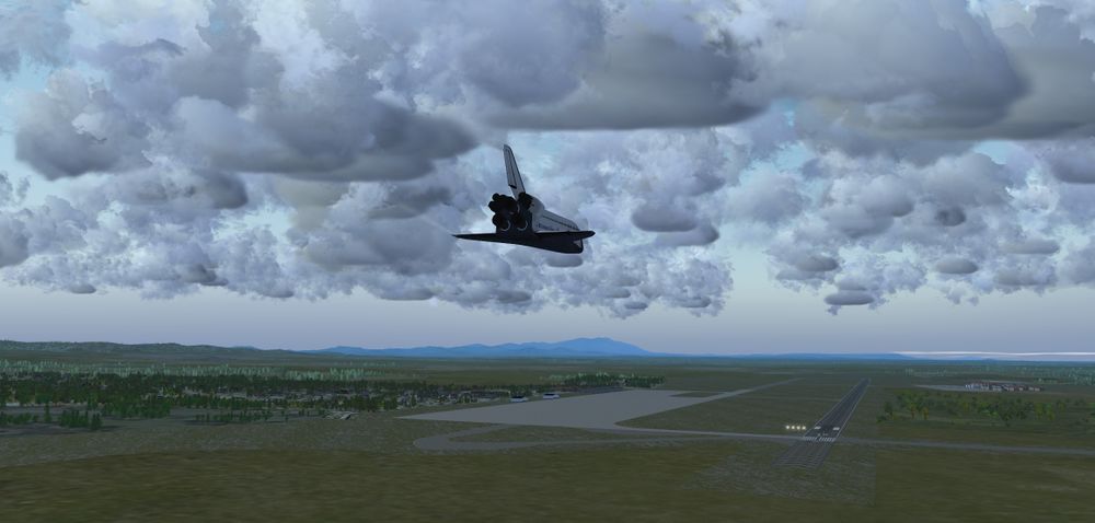
Pre flare at 2000 feet RA.
A bit too much winds and turbulences, nice challenge and Carrier landing incoming.
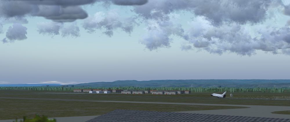
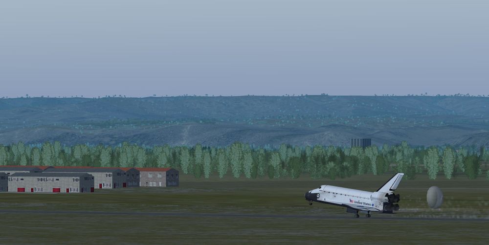
Touchdown on speed, a bit long though. Hopefully, Runway is long enough, no stress.
"Wheels Stopped, Welcome to ZZA guys and good job"
We made it, from Florida to Spain in 30 mn, quick but a bit expensive, isn’t it? :)


