Flying the Shuttle - Deorbit Preparation Advanced
You will find here a tutorial concerning all the Entry preparation using real procedures and Checklists
Nominally, Pre Deorbit Preparation begins 4 h before deorbit burn, 4 h 45 min before landing at KSC. Long preparation to allow sufficient time to the Freon stocked in Radiators to be cold soaked. This cold Freon trapped in Radiators will allow an extra 15 min of Freon Cooling during latest phase of entry (below 120000 ft) where Flash Evaporators (FES) are not efficient anymore due to the increase of external pressure.
For practical reasons, we will start the mission 1h30 before KSC landing.
| Tip A lot of things to do, I advise you to use 1/8 or 1/16 time compression for preparation phases, and to go back to normal speed for phases like payload doors closure or pre/post burn preparations. |
It works quite well like that. When we start the mission, we have 45 min before deorbit burn, and we have to do 4 h of procedure in 45 min, hence the need for slow time compression. By doing so, you will be back on the normal time line with real time compression around 10 to 15 min before the burn, then the last 50 min can be done in normal time compression or a bit accelerated for coasting phases (between burn and Entry Interface for example).
| Note
Many of the actions are not mandatory, in essence they will not influence directly the safety of the flight and return to Earth. If you want to skip some of the actions, you can stick to the In Game Checklists that give you the mandatory items to be done to perform the entry and landing well. |
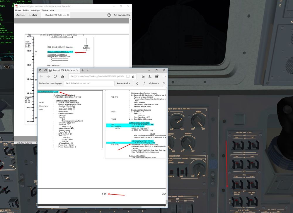
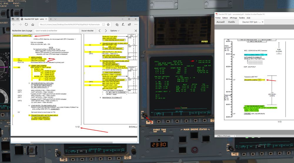
Annotated checklists from real documentation: Flying the Shuttle - Space Shuttle Checklists
We will use in this tutorial the Deorbit Preparation Checklist.
| Tip
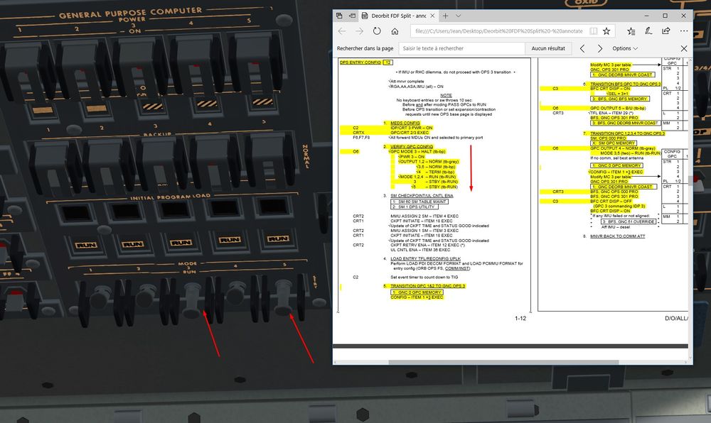
Small note on GPC and Keyboard procedure:
|
Note
|
| Space Shuttle |
|---|
| Main article |
| Technical |
| Checklists |
| Nominal Operations |
| Nominal Operations Advanced Tutorials |
| Intact Aborts |
| The other space shuttle |
Deorbit Preparation up to GPC Reconfiguration
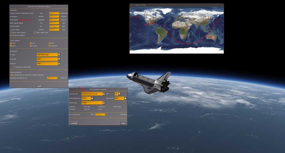
We want to land at KSC, so the scenario will start nearby the destination field to have at least one Orbit to prepare the Shuttle. Earth is rotating, so in one Orbit we will not be exactly overhead KSC if we start right above it at beginning of the mission.
To account of one Orbit of ground track drift, we have to start a bit further to the East, around 1000 NM for a 50° inclination Orbit (like the one of ISS). 1000 NM corresponds to 20° of addition in Eastern Longitude. (For a 30° inclination Orbit, numbers are around 600 NM of drift for one Orbit, and 10° of East Longitude to had.)
Also, we have to specify a Heading. We will take 138° (90° + 48°) which will place us to a Descending Node (in regards of Equator reference) at Mission start and allow us to do later the entry overhead the USA instead of Central America.
Settings to enter in Launch Menu:

Start FlightGear with the commandline options
--aircraft=SpaceShuttle-ISS --lat=28.0 --lon=-60.0 --heading=138.0 --timeofday=morning
Same Latitude than Landing Site, 20° more in Eastern Longitude than KSC as explained and south east heading.
Little trick here, a heading of 45° or 135° places you half way on your orbit, so inclination will be twice the latitude (here around 50 ° as wanted)
A heading of 90° will place at an apogee or perigee, so inclination will be equal to the latitude set.
Be careful if you put a heading of 90° to have a latitude equal or higher than the one from landing site. If not, your inclination will be lower than the Landing Site latitude and it will be almost impossible to land there.
Let's set the good parameters for the landing field in Entry Guidance Computer Window to have some up to date visual clues on the trajectory map.
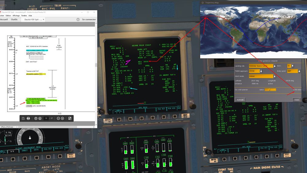
The dark red banana left of the screen shows us the Entry Interface (EI) (EI begins at 400000 ft). We want it to be ideally at 4100 NM from KSC, I took a bit less around 3900 NM (Between 3000 and 4000 NM is ok, Reentry angle will be a bit steeper but within limits).
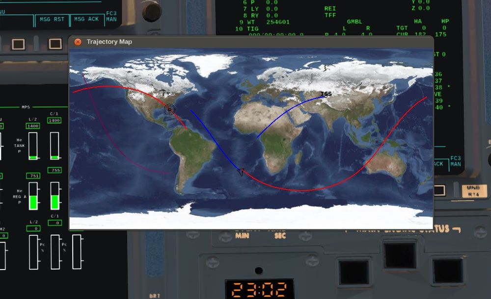
A screen shot later into he mission to show some important features in the trajectory map:
- Blue Orbit with the Shuttle on it is the present Orbit.
- Red one is the forecasted ground track for next Orbit.
We see that starting with a bit more of Eastern Longitude is working well and we gonna overfly perfectly KSC during next Orbit (hence during entry phase).
It can still vary a bit due to dynamical calculations, but it works great.
Optional Part for Advanced GPC users
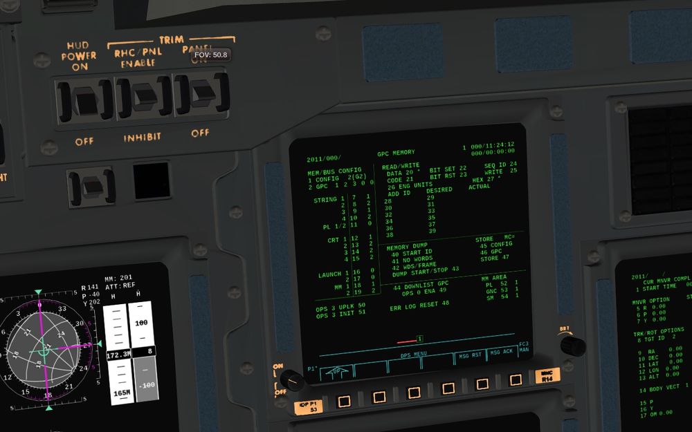
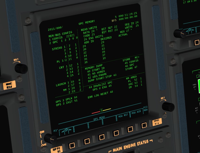
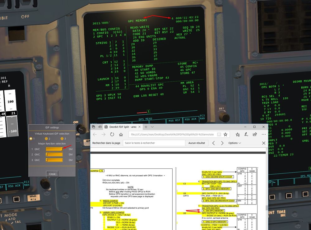
For those who use Advanced GPC setting, we have to do 2 or 3 small changes to have the correct configuration in Nominal Bus Assignement Table (NBAT) in order to do the correct transition towards OPS 3 later on.
Some hints here for better understanding: Flying the Shuttle - Launch And Post Insertion Advanced#Post Insertion: Advanced GPC reconfiguration GPC reconfiguration from Ascent to Orbit Operations
We will do a short procedure compared to the full one needed to go from OPS 1 to OPS 2. We have to re assign some bus and put GPC 3 and 5 in sleep mode.
Once done, you can save the state. GPC configuration is well supported by save state and you can use this save as a starting point for future missions.
Let's go for 3 min of work in Slow time compression.
Spec 0 Item 9 +1 Item 10 +2 Item 14+2 to deassign GPC 3 from its bus
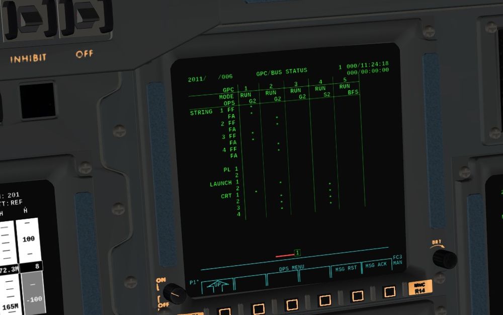
Results - run Ops 201 Spec 6
Then we bring GPC 5 BFS on the central Display CRT 3 with BFC Display switch on pedestal and we put it in system software only OPS 0
Then turn the BFS back off.
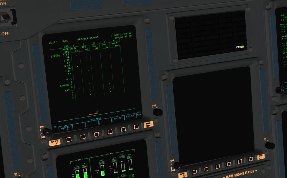
GPC 3 and 5 in Halt mode, GPC 4 in Terminate Output
CRT 3 off and Spec 6 to check good Bus assignment
That's it, done
End of optional part
Let's go!
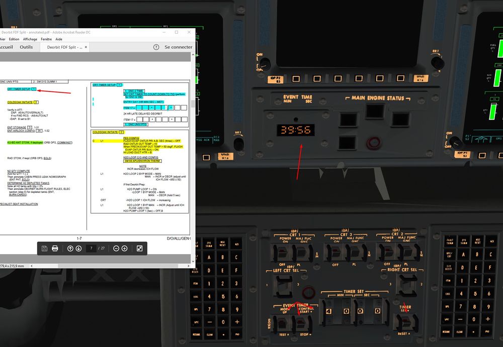
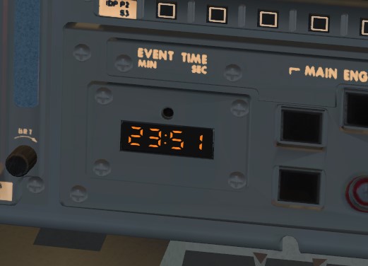
1) We set up the timer on the time remaining before De orbit burn. (4 h in real, 45 min for us to have the burn in half an Orbit in order to create a Perigee overhead KSC) We can do it via SPEC 2 which bring us to a complex page to handle timer, or you can do it (like in the screen) directly on the Central Event Time, more practical I find.
It is nice also to handle your time compression and know how much time you have to finish preparation before the burn (and you can adjust time compression in consequence).
2) Cold soak Procedure Then, I love that name.
Process is to cool the Freon in the radiators and to stock it inside.
Thermal management in the sim is really well done, and there is some differences with the real procedure due to the huge complexity of a thermal model in a space craft like the Shuttle, where dozens of systems are exchanging heat.
In game procedure will be then a bit shortened.
For the most Curious, some lines about what happens in reality
- The Freon going out of the radiators will join the general Freon Loop (hot) in order to cool it. In normal mode, Freon in the main loops has to be cooled down around 39°F after the cold Freon from Radiators is mixed with the hot one.
- For the Cold Soak Procedure, we switch the Freon Out Temp mode into Hi. Now, the target temperature for Freon cooling is raised to 57°F instead of 39°F, hotter so.
- Hence, the flow of Freon in radiators will be slower, we need less cold Freon to cool the main Loop. This slow flow will have the consequence to cool more than usual the Freon (stagnating) in the radiators, it is the cold soaked. To sum up, with less cooling required in Main Freon Loop, the Freon in the Radiators becomes cooler because it stays more time in them.
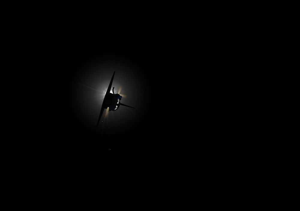
- Also, Shuttle moves into a Tail to Sun attitude (tail of the shuttle pointing towards the Sun) to have the radiators in the Shadow.
- 1 h after the beginning of that procedure, Freon in the Radiators will be stocked in it and save for later. To do that, Radiators are By Passed and Freon Loops are isolated from Radiators.
- Cooling will be now into the hands of the FES that will be re activated for the last hours of Orbit Operations.
Now how it works in the sim.
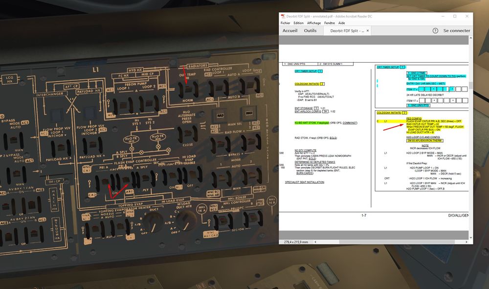
We check that FES are off and we switch Radiators to Out Temp Hi
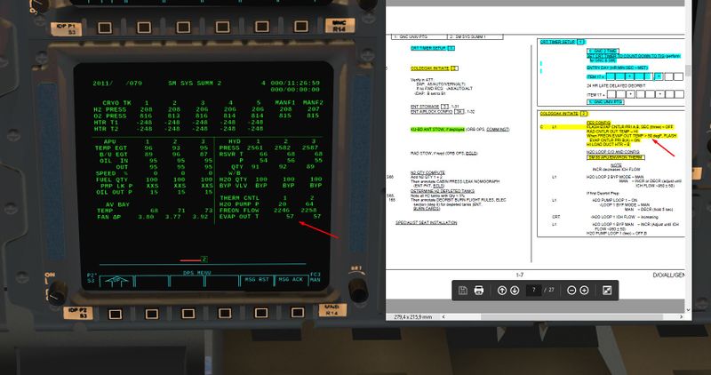
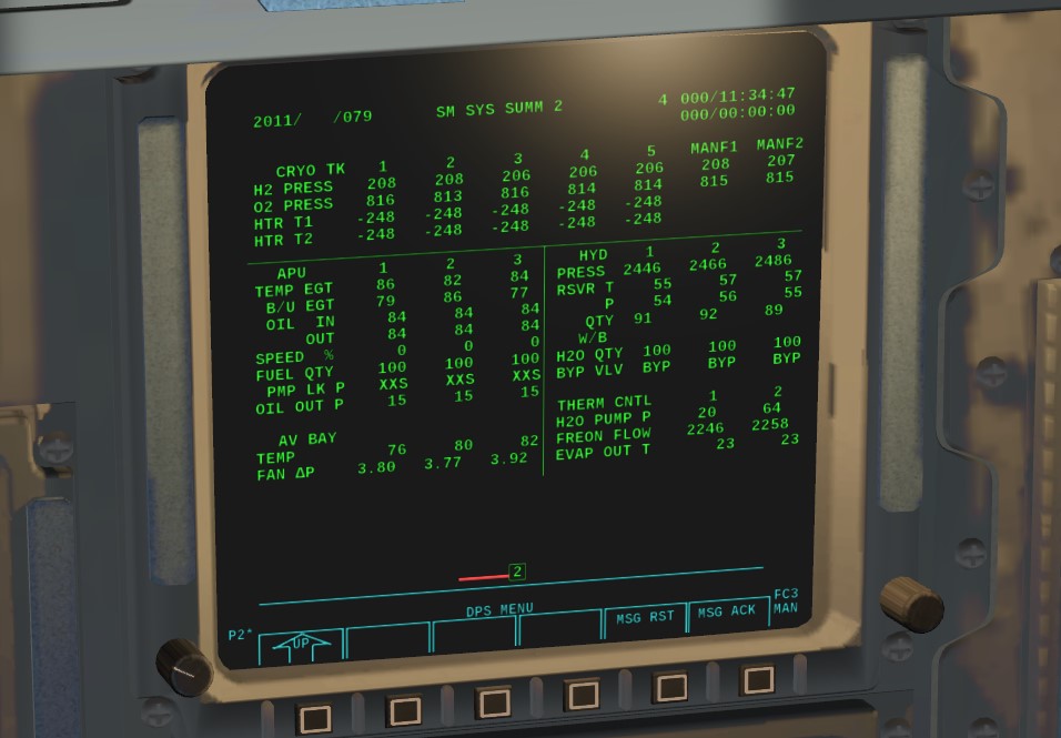
A quick glance on Freon Evap Out Temp SPEC 79 in SM Mode (Value is quite perfect in the example, it can vary a bit, but below 70°F is fine)
This value reflects temperature of Freon Main Loops after their cooling through Radiators and FES. FES are not active yet, so value indicates the Freon Temp after cold Freon going out of Radiators mixes with Main Freon Loop.
We activate then FES (primary A or B for different water tanks supply) Primary A supplies FES with A or B (normally only B) water tanks, Primary B with C or D (normally only D) water tanks if the cross over valve between tank A,B and C,D is closed.
Also we activate heaters fo Hi Load Evap Duct to avoid freezing
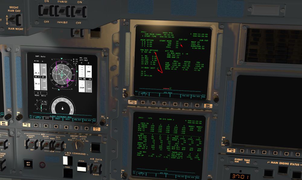
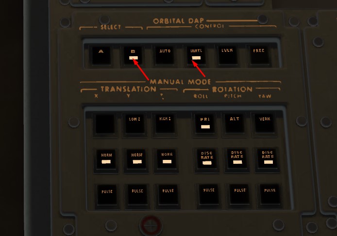
We will go into Tail Sun attitude using the OPS 201 UNIV PTG
Item 8+4 to choose Suns as target
Item 14 + 2 to choose -X shuttle axe as a reference (Tail)
Item 19 and DAP Auto to track the wanted attitude
Once in correct attitude, we can do ITEM 21 to cancel the track and go back in DAP inertial to maintain a nice Tail Sun inertial attitude. It will save some RCS fuel, track function is quite fuel consuming
Result
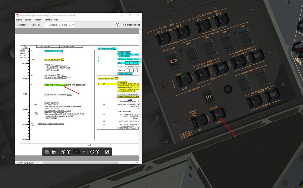
We stow Ku Antenna
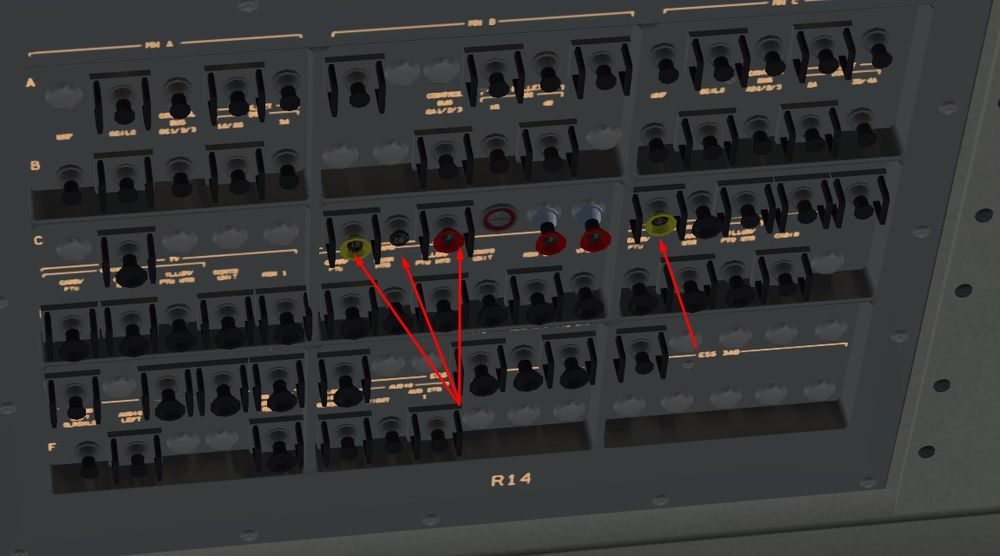
And we open ( closed) the breakers associated with the Ku antenna
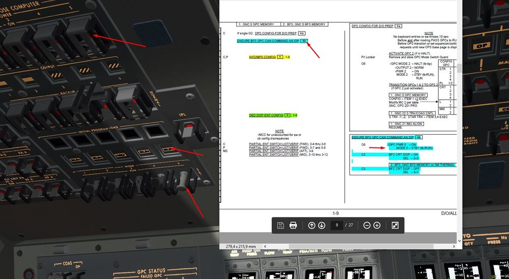
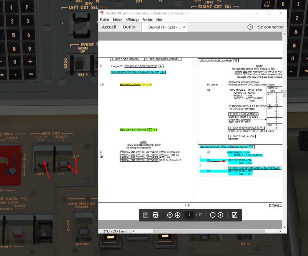
3) We check that the GPC running the BFS can display its data on the a CRT (3 by convention)
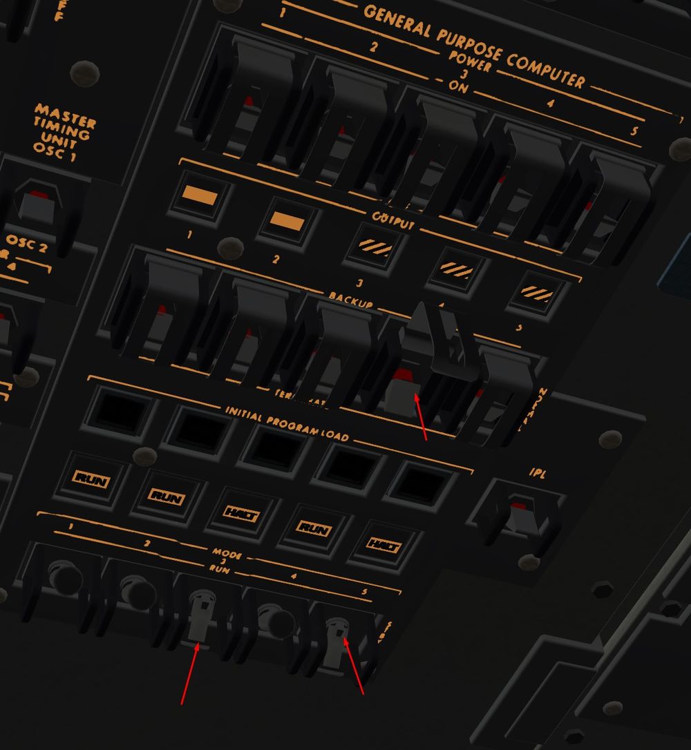
Let's put the GPC 5 back to life with STBY mode.
BFC CRT display On to view its data on CRT 3
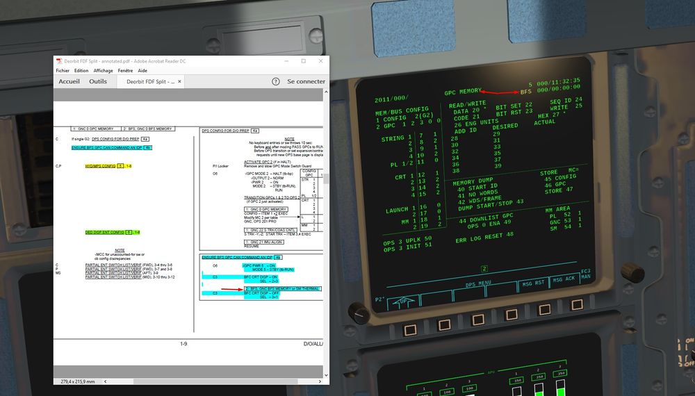
We check that on CRT 3 we have GPC5/BFS in OPS 0 memory mode
Then reversed steps, we switch back to Off the BFC CRT switch display.
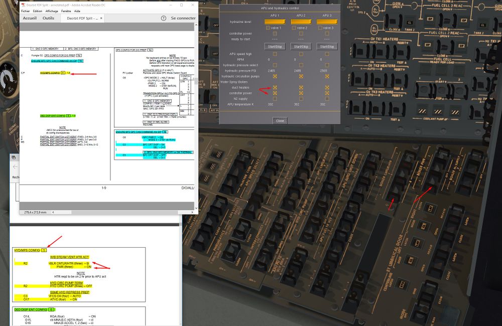
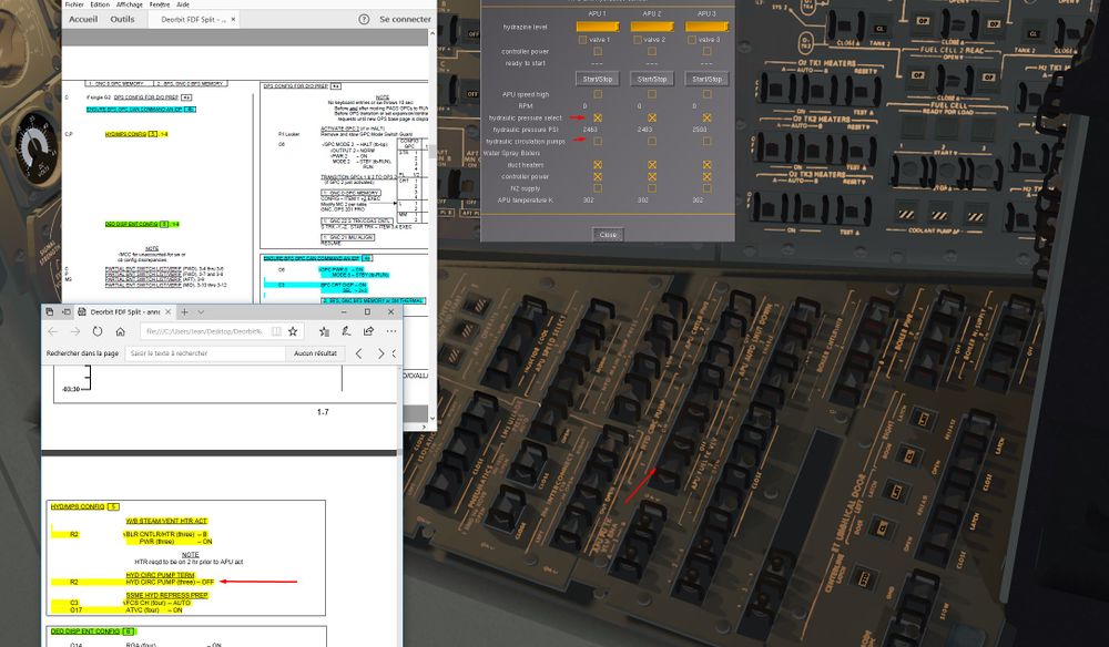
4) Some Hydraulic system reconfiguration
We check that the Water Boilers Heaters are On and we activate their controllers
Recirculation Pumps are switched Off, just a few hours before entry, no need anymore for Hydraulic Thermal conditioning of Hydraulically activated Shuttle parts.
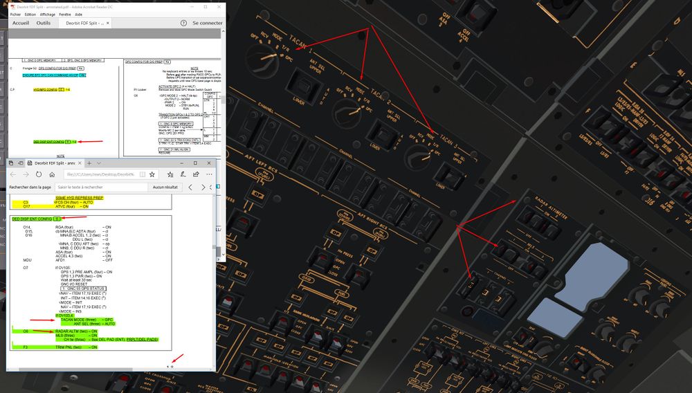
5) Time for Navaids to be back on lin.
Tacan, Radio Altimeters and MLS are switched On ( and correct channels for MLS ie. 8 for KSC runway 15)
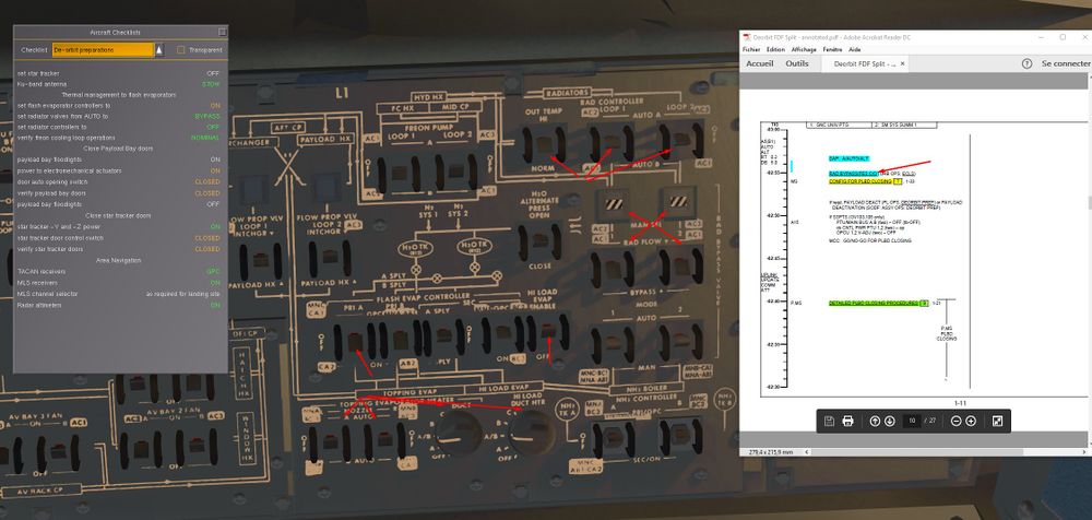
6) Back to the Cold Soak Procedure.
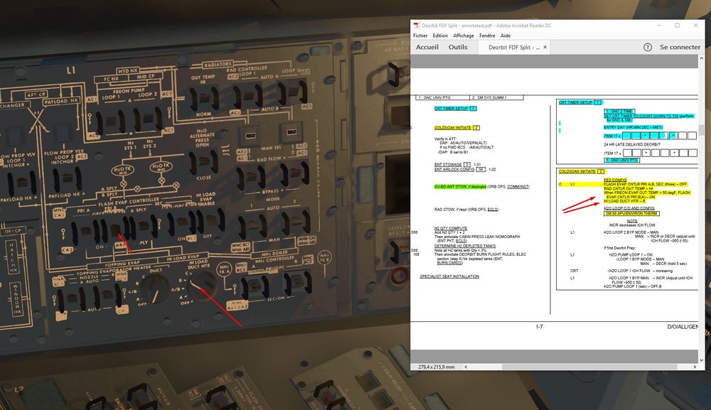
We By Pass the radiators by isolating them from main Freon Loops. Small portion of cold Freon will be stuck in the radiators.
We activate also the Hi Load capacity of FES (and associated heaters) to allow a more efficient Freon Cooling.
In reality, Astronauts had to check also the good Behavior of the Secondary FES, which works a bit differently (cooling the Freon at 62° instead of 39°).
Aim here was to test it to avoid further maintenance actions on the ground during turnaround of the Shuttle. Easier to test it in Orbit than on the ground I guess.
Temperature looks good
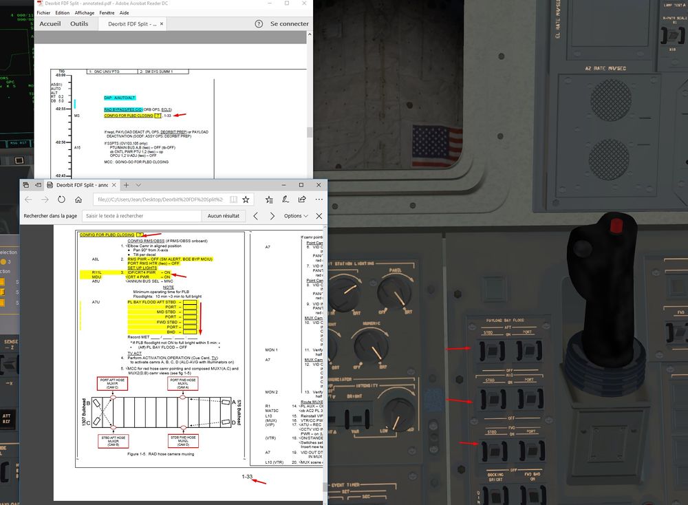
7) We configure the bay for Doors closing
We just need to activate payload bay Lights
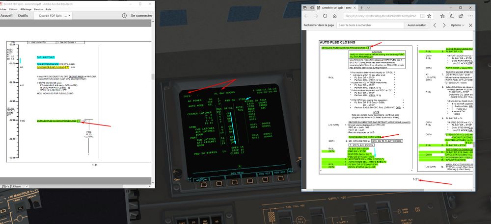
8) Let's close the doors.
Several way to do it, Automatic, or Manual.
We choose Automatic, and it will be enough complex like that.
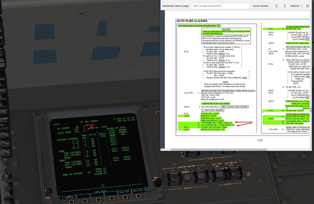
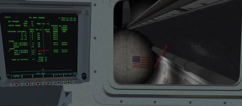
We go in Major Function SM and OPS 202 to access the PL Bay doors display.
We check that the different parameters are coherent ( Doors opened, Latches position, no AC current,..)
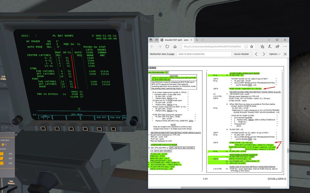
AC current and auto mode
Item1 and Item 3
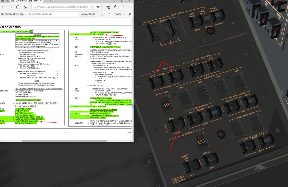
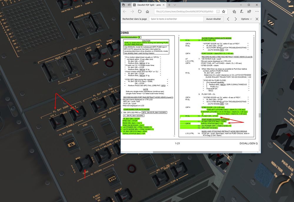
Mechanical systems on and we close the doors
We monitor that everything is ok , and the sequence correct. First Port door and latches, then Starboard door and associated latches, finally latches between the two doors.
At the end, we should have that
Mechanical systems off and AC current turned off Item 2
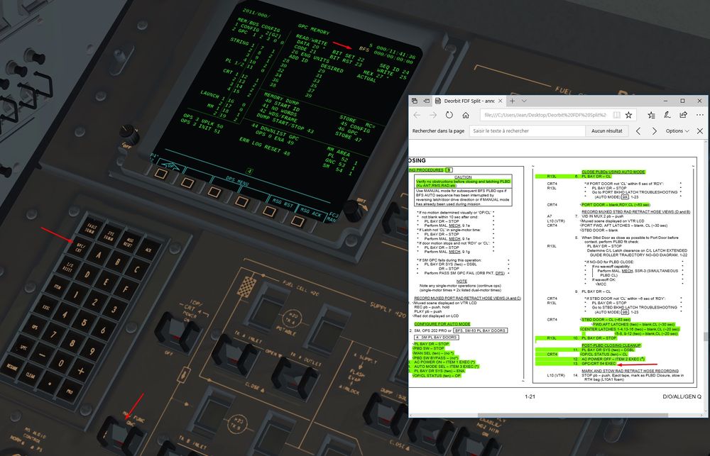
Finally, we linked the CRT 4 to GPC 5 GPC/CRT 54 and we turned it off
With good use of time compression, we should be around 20 min on Event Time at this stage
9) Post doors closing actions
Pretty simple, we switch off the lights
10) Time to configure the GPC for entry
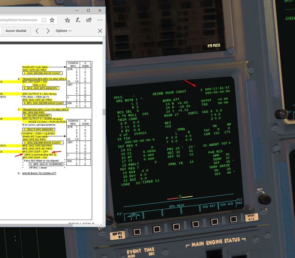
In Simple GPC mode, we just have to transition towards OPS 3 by OPS 301 PRO to load the good NBAT for every GPC.
You can then skip the next part and proceed directly to
In Advanced GPC, it's gonna be a bit more challenging and time consuming.
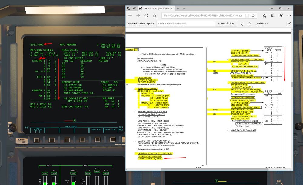
Advanced GPC Reconfiguration for Entry OPS 3
It requires a bit of experience and reading about GPC, especially about their philosophy. It can be a bit overwhelming otherwise.
The goal here is to put GPC 1 to 4 in OPS 3 Entry Software with 2 Critical Bus on each (redundancy), and also to configure the independent BFS in OPS3.
GPC3 and 5 are sleeping, GPC 4 is doing the System Management and does not emit on Critical Bus.
Hence, we will have to proceed step by step as we have different GPC in different Mode and Major Function to put back together in OPS3.
First GPC 1 and 2 in OPS3. Then BFS in OPS3. Then GPC4 out of SM. Waking up of GPC 3. Finally, we will link GPC 1 to 4 together in a Redundant Set in OPS3.
We turn on CRT 3 and we assign it a GPC GPC/CRT 23
We check on O6 panel the good position of switches
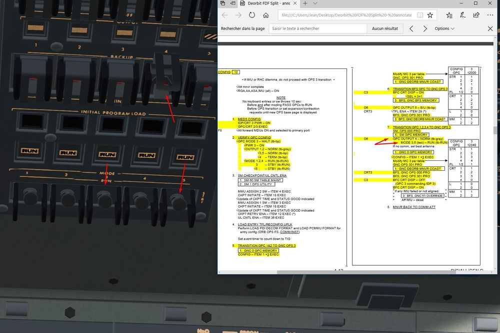
GPC 3 and 5 are put back to work by setting them in STBY mode first
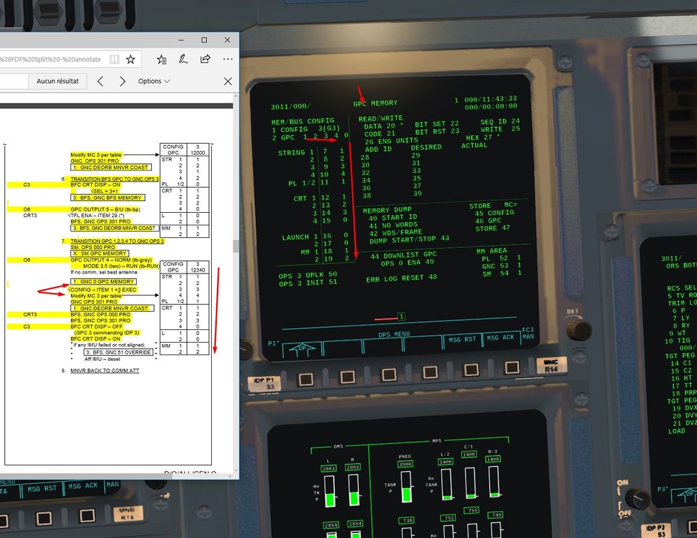
We configure the G3 NBAT (Nominal Bus Assignement Table for OPS 3 entry software) in order to switch GPC 1 and 2 in OPS3
Do not forget Item 4+0 item 5+0 to avoid that GPC 3 or 4 are loaded with OPS 3 too early
We transition to OPS 3 OPS 301 PRO
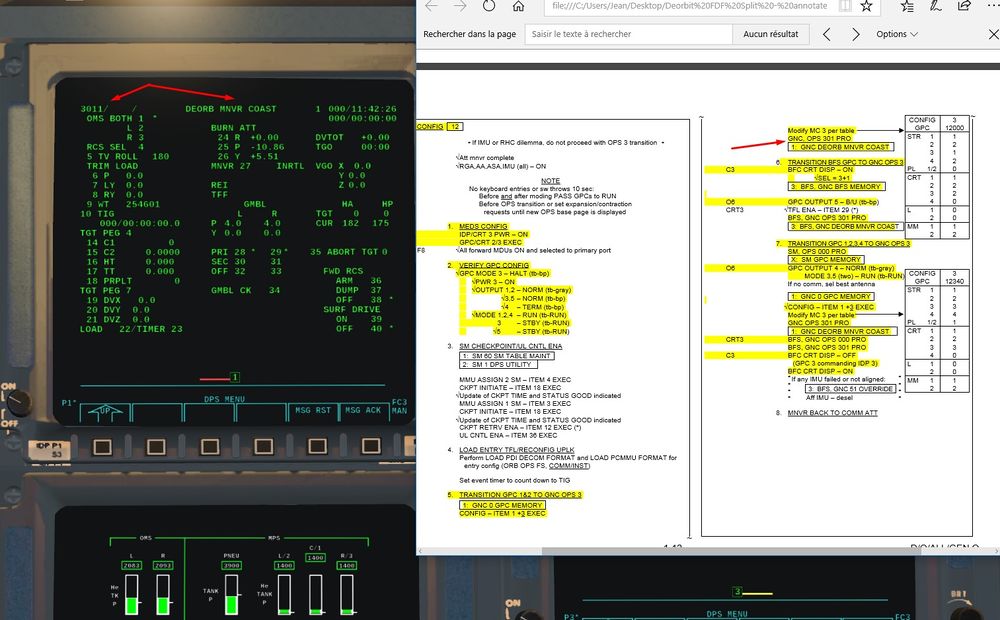
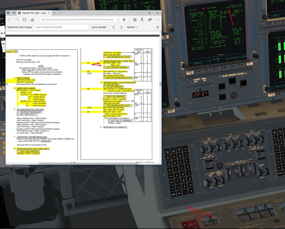
Time for the BFS now, like before, we display it on CRT 3
Then we load the OPS 3 into the BFS with OPS 301 PRO on CRT 3
We stop the SM Function within the GPC 4
For that, we display the GPC 4 on a CRT (1 here) GPC/CRT 14 EXEC and we switch to System Software mode only OPS 0 PRO
We put back GPC 4 to normal Output to allow it to emit on Flight critical Bus.
GPC 3 and 5 are put back to RUN mode (STBY previously).
We reconfigure the NBAT G 3 like before, but that time we include GPC 3 and 4.
Do not forget item 4+3 item 5+4, if not only GPC 1 and 2 will be in the redundant OPS 3 set.
And finally OPS301PRO to load the new NBAT and put GPC 3 and 4 in OPS 3 with their friends GPC 1 and 2
We recycle once the BFC Display Switch in Off position to check that the CRT 3 is well commanded by the GPC 3 when BFS is not diplayed on CRT 3.
Then we put back the display switch to On to have th BFS on CRT 3 for the reminder of the mission.
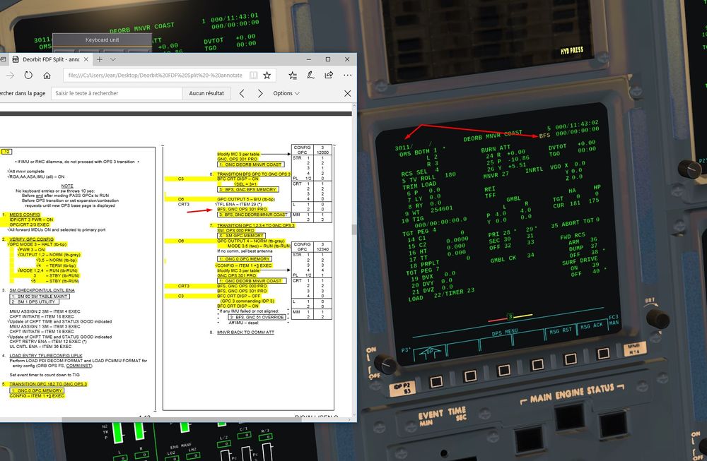
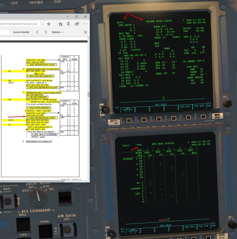
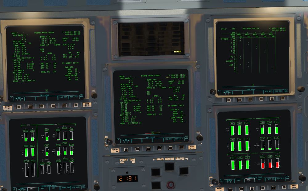
Here the global result we should have
GPC 5 on CRT 3
And on SPEC 6 ( CRT 2), we can check that GPC 1 to 4 emit on 2 Critical Bus each, CRT 1 and 2 are commanded by a GPC ( 4 is off)
Perfect, Awesome level of fidelity to real stuff here
Reconfiguration of GPC is done, we can go back to our preparation.
From GPC reconfigured until end of Deorbit Preparation
Let's continue
11) We are now going to calculate the Deorbit Burn Solution
First of all, Center of Gravity matter (COG)
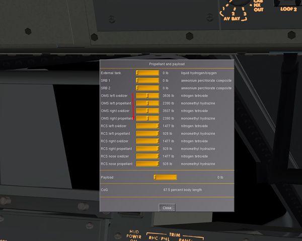
We start the mission with OMS fully filled with propellant, and we will use around 30% to 40% of it max during the burn.
We will have too much remaining, hence Afterward COG and Stability problems during entry.
2 solutions: Either we incorporate an out of plane component (y LVLH axis) during the burn (at least 400 ft/s) to eliminate propellant without affecting shape of the orbit. Or we edit the quantity of OMS propellant in the menu for that (picture below)
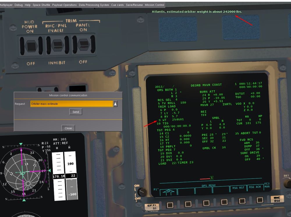
We gonna load initial parameters: Trim and gross weight of the Orbiter
For the trim, ITEM 7 -5.7+5.7 It allows the nozzles to align parallel with Shuttle X axis going through the CoG for a 2 engines burn. With no trim, Nozzles are not naturally align with that axis but offset by 6° outward in case of a single engine burn, where the engine will have to push through the Cog and not parallel (hence with a sideslip angle).
ERRATUM: For the rest of the screens until the burn, you can see a Star (*) right of L2 parameter. It indicates that I wrongly choose a single engine (left one) burn.
It is totally feasable, but duration of the burn and trim have to be different.
I saw that too late ( during the burn, just one engine ignited and I saw that mistake) So, I did again all the prep and a two engine burn, but didn't do again the screens.
Disregard that mistake, we will do a two engines burn, and the star (*) should be right to item OMS BOTH 1 * and burn time TGO should be halved, around 3 mn
Orbiter weight also changed as we dumped fuel in OMS tanks, so have to ask MCC the new one and correct it in the computer.
Item 9 + 242000
What is the intensity of the burn?
We have a Perigee at 175 NM and we want to decrease it above KSC around 20 NM, reminder of the rule of thumb 2ft/s for 1 NM of height
We have to loose 155 NM of height, so around 310 ft/s of speed to loose.
We affinate that and take Vx = -280 ft/s (Negative speed on X LVLH axis because we want to do a retrograde burn, we have a quasi circular Orbit, so X LVLH axis is almost the same than the Velocity Vector one, hence the burn on X axis only and no Z component)
Height of Perigee (HP) in Target (TGT) is 22 Nm, close enough.
Item 19 - 280
Item 22 to load
We can see that REI appears, very important value to know when we have to perform the burn
Reentry Interface Range, or the distance between Entry Interface (400'000 ft) and landing site (KSC)
We saw earlier that we wanted to have REI around 4000 NM to have a good angle of entry, not too flat, not too steep. So when REI value approach 4000 NM, we will press EXEC on the keyboard to perform the burn.
It works well like that.
In real life, MCC would upload a burn solution based on different variables ( linear equation linking horizontal and vertical velocity wanted at EI, angle Theta between burn and EI interface, and height HT wanted at EI so 400'000 ftt) You can see those parameters below TGT PEG 4, not implemented yet.
Outcome would be the same, just a different way, more efficient and safe (closed loop guidance) for Deorbit burn in Real (critical burn)
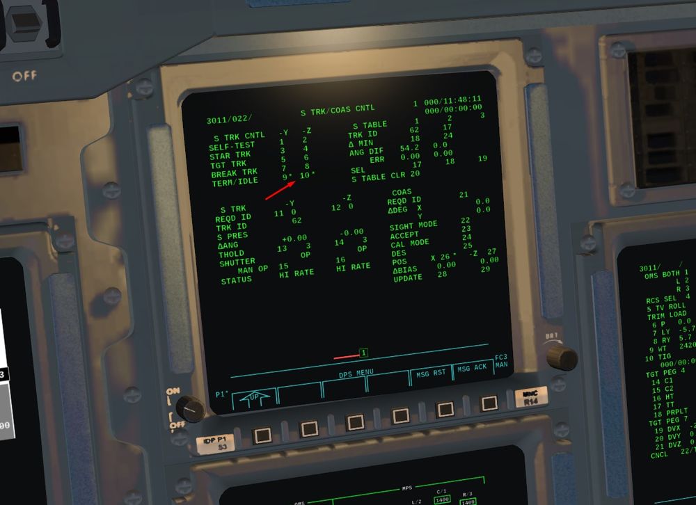
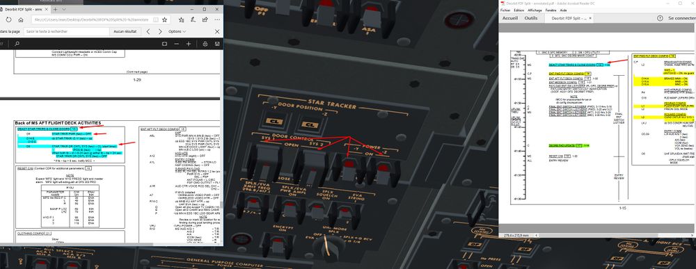
12) We shut down the Star Trackers
Spec 22 Pro Item 9 and item 10
ST Software on Idle first
Now, Mechanical shut down of the ST
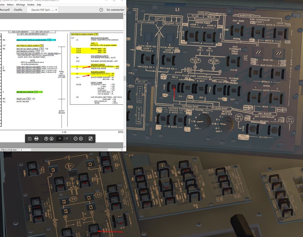
13) We finalize entry cockpit configuration.
FES on GPC to allow Computers to control the FES during entry. Also, small changes in Pressurisation Control System to be fed by system 1.
Optional
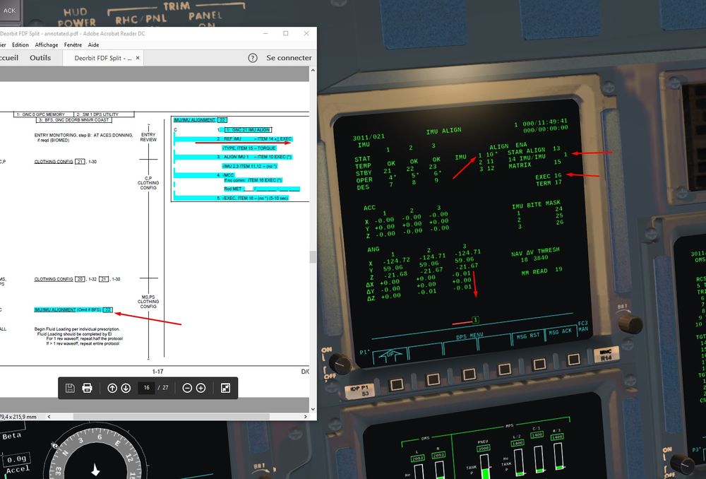
14) We can do an IMU alignment before the entry. At this stage, it is a IMU /IMU alignment ( one IMU as a reference) Star Trackers are off, so Stars are not available to serve as a reference to align the IMU.
Spec 21 pro to go on IMU display page.
I am not writing too much about it, I will detail that longer in a specific part (a lot has to be say about IMU capabilities )
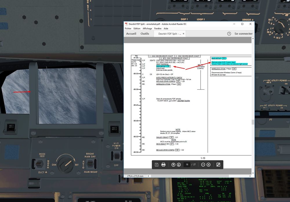
15) Final Step, we remove the HUD cover (click on grey part)
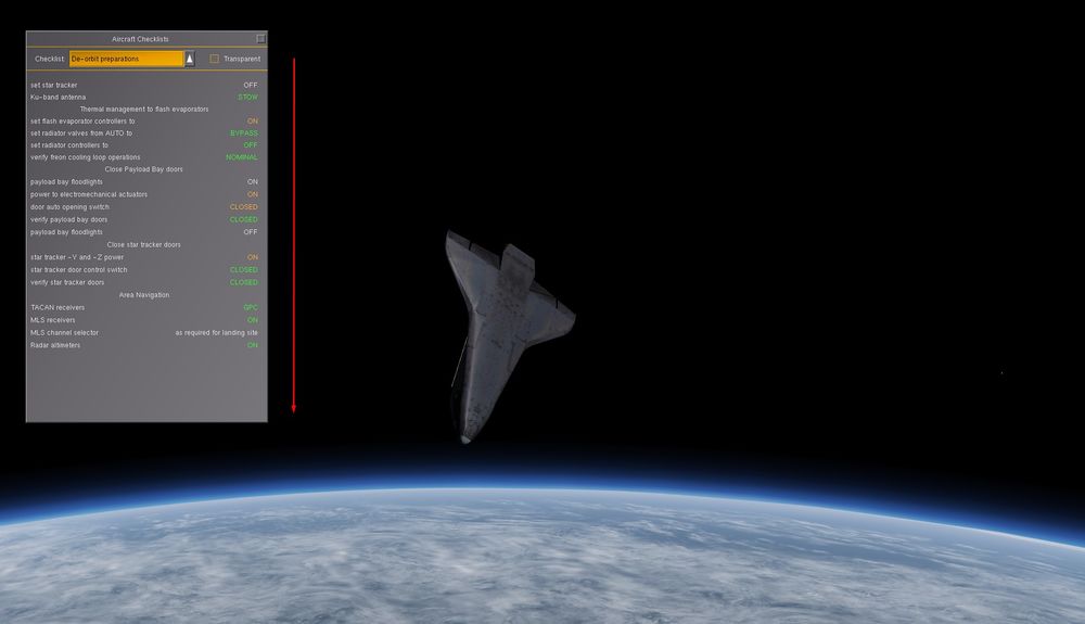
And a cross check of all what we did with the In Game checks
Next step will be the Deorbit burn followed by final Entry preparation. Then Entry, TAEM and Landing at KSC


