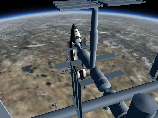
Flying the Shuttle - Orbital Operations
| Note This article refers to the SpaceShuttle in the FGAddon repository. |
| Space Shuttle |
|---|
| Main article |
| Technical |
| Checklists |
| Nominal Operations |
| Nominal Operations Advanced Tutorials |
| Intact Aborts |
| The other space shuttle |
This mission phase can directly be started using --aircraft=SpaceShuttle-orbit on the command line.
What are we trying to do?
For most of its mission duration (up to some two weeks) the Shuttle remains in an orbit around Earth at an altitude of 300 - 600 km dependent on payload and mission purpose. On the relevant timescale, such an orbit is very stable, hence the crew needs to do little actual flying. Also, the residual airstream is very faint, hence the body axis of the Shuttle can point very differently from the direction of motion - the Shuttle can in fact assume pretty much any attitude.
What is a concern is thermal management - sunward pointing surfaces can get uncomfortably hot whereas surfaces away from the sun can get so cold that working outside even in a space suit is uncomfortable, The chill of space can also render thrusters non-operative. Thermal management by controlling attitude is hence an important part of in-orbit operations.
The maneuvering capability after ET separation is greatly reduced since the main engines can no longer be supplied with propellant. The remaining capability of the OMS engines is enough for fine-adjusting the orbital parameters for rendezvous purposes with other orbiting objects, but not for significant alterations of the orbit. Orbital mechanics hence governs all motions, and its laws need to be understood and taken into account when trying to maneuver near another craft or space station.
The tasks in orbit therefore are:
- manage attitude according to thermal and mission requirements
- correct orbital parameters for docking or rendezvous purposes
- do routine maintenance and housekeeping to keep the Shuttle's systems functional
Some theory
Unperturbed orbital motion
Orbital motion is characterized by the absence of dissipative forces (i.e. forces which depend on velocity) such as friction. To first approximation the only force that matters in orbit is gravity, and one way to picture why an object remains in orbit is that gravitational attraction is balanced by the centrifugal force of an object moving quickly in a near-circular motion (there are other ways to picture the same thing, up to and including the realization that an orbit is a geodesic straight line through curved spacetime).
In the absence of dissipative forces or thrust, orbital energy and angular momentum are conserved and all motions are reversible. Thus, if the Shuttle is on an eccentric orbit and rises to a high apogee, its potential energy increases as it climbs upward, but energy conservation demands that its kinetic energy has to decrease, so it will lose velocity in the process. After reaching apogee, the Shuttle will fall down again and re-gain the same velocity it lost before, and reach the same values for apogee and perigee in each orbit.
The inclination of the orbital plane is likewise fixed by angular momentum conservation (the angular momentum vector is always perpendicular to the orbital plane and never changes), so the Shuttle will cross the equator under the same angle during a mission.
In fact, in inertial coordinates apogee and perigee will even always be at the same position. If Earth would not rotate, the groundtrack of the Shuttle would look very simple and would never change, the Shuttle would always orbit over the same location. However, in reality Earth does rotate, and so the groundtrack displays a characteristic shift in every orbit (as seen from the picture).
What is determined by orbital motion is the time-dependent position of the Shuttle's center of gravity. However, the Shuttle can rotate around all three axes around this without disturbing the orbital motion. There is an angular momentum vector associated with this motion as well, and this is likewise conserved, i.e. once the Shuttle rotates, it will continue to do so till this motion is countered by an external torque. Likewise, if the Shuttle is in some attitude, it will (to first approximation) keep this attitude till a torque is applied. Note that attitude here refers to inertial attitude, not attitude relative to the horizon - during an orbit, an object holding inertial attitude will seemingly perform a full rotation around the pitch axis with respect to the local horizon (picture an arrow rotating around a sphere with the arrow always pointing the same direction in space - it will appear to rotate when referenced from the sphere).
Orbital maneuvering basics
The Shuttle's motion in orbit defines a special coordinate system in which one direction ('prograde') is along the current velocity vector with the opposite vector called 'retrograde', one direction is along the gravitational force ('radial'), i.e. towards Earth and its opposite vector and the third special direction is perpendicular to the previous two (called 'normal' and 'anti-normal'). Understanding this is important for using thrusters for orbital maneuvering.
The reason is that these directions are special because prograde and retrograde burns change only the kinetic part of the orbital energy (or magnitude or angular momentum) whereas normal and anti-normal burns only change the direction of the orbital angular momentum but not energy or magnitude. Since these are the conserved quantities from which all orbital motion follows, any maneuver leading from one orbit into another can be decomposed into a series of properly timed prograde, retrograde, normal and anti-normal burns. Radial burns are not useful in this context since they mix changes to kinetic and potential energy and hence are counter-intuitive, but accomplish nothing that could not be done equally well by a prograde/retrograde burn.
Let's first consider the normal burns. For the Shuttle in a circular orbit, all they do is change the orbital plane, which is manifest in an inclination change - the Shuttle alters the angle at which it crosses the equator. For an object in a circular orbit to maneuver to the same orbit as another object in a circular orbit at different inclination, what needs to be done is a change of the orbital plane to the target at one of the crossing point of the two orbits (two orbits are either the same or always have two crossing points).
Unfortunately, changes of the orbital plane are energetically very expensive - it is in fact cheaper to de-orbit and launch again than to change inclination by 90 degrees (because de-orbiting at least can utilize the atmosphere for braking). Thus, the OMS engines of the Space Shuttle provide hardly any capability to change inclination - expect the inclination to be changed by a degree at most once you are in orbit.
Therefore it is important that if the Shuttle needs to reach a certain inclination or must orbit in a certain orbital plane, this is established to a good precision during the ascent. Fixing orbital plane later will not work.
In contrast, a prograde burn raises the orbit, a retrograde burn lowers the orbit. If you are in a circular orbit and execute a prograde burn, you will rise apogee just 180 degrees around, i.e. opposite to your current location. If you then coast for half an orbit till you reach the new apogee and execute a second prograde burn, perigee will rise and you can re-circularize the orbit. Conversely, if you are in a circular orbit and execute a retrograde burn, you will lower perigee opposite to your location, and you can re-circularize at perigee using a second retrograde burn.
Unlike plane changes, altitude changes of an orbit require much less energy, so raising an orbit from 150 km to 600 km and back for an entry trajectory is quite possible using the Space Shuttle's OMS engines.
As hinted, all orbital burns should be executed at specific locations, and ideally they should happen as instantaneous velocity changes. However, the OMS engines have actually rather low thrust and are hardly instantaneous, so in reality the finite time of a burn should be spread half and half around the specific point where the ideal instantaneous burn is timed.
Matching a second orbit
Suppose you are in one orbit and you want to reach ISS which is in a different orbit - different altitude, different plane, not at your location. How would you do it? As argued above, this can be done in a series of simple prograde/retrograde and normal/anti-normal burns.
- First, plan ahead: if you're lower, raise orbit before plane changes (plane changes are energetically cheaper in higher orbits), otherwise change plane first, then lower
- If you need to raise orbit, do a prograde burn. Watch apogee climb to the desired value and stop the burn. Coast for half an orbit till you reach apogee, execute a second prograde burn at apogee and watch perigee climb up to the same value - you are now at a circular orbit at the target altitude, but the target might orbit in a different plane and at different inclination.
- Coast to the next crossing point with the ISS. From the way the orbits intersect, it's clear whether you need to burn normal or anti-normal ('turn left or right'). At the intersection point, do the burn till you match target inclination. You're now in the same orbit as the target, but not in the same location.
Adjusting location is somewhat tricky - intuitively you will assume that you and the target are in the same inertial system, but in fact you're not. If the target is 100 km ahead, you might be tempted to accelerate towards it, to simply fly there - but what will happen is that you effectively do a prograde burn, so rather than reaching the target, you will raise orbital altitude, slow down and see the target move further away.
What you need to do is in fact do a retrograde burn, fall down to a lower orbit where you orbit faster, catch up with the target and do a properly timed prograde burn to raise again.
Only if you are very close to the target (perhaps < 50 km) you can start to dispense with orbital mechanics and simply 'fly there'.
So, the strategy to reach the same location as an object in the same orbit is:
- Make your orbit more eccentric - if you're ahead or target, raise your orbit slightly, if you're behind, lower it. Over time, your new orbit will bring you to an intersection with the target at which you can raise/lower orbit again (this may actually take a dozen orbits or so - rendezvous are nothing that's done in a hurry).
Since you can't do serious plane changes with the Shuttle, if you need to reach the ISS in orbit, you need to launch at the right time (i.e. there are proper launch windows). This time is when ISS just passes over the launch site - if you launch then into the same inclination, you will automatically end up in the same orbital plane, slightly behind the target. This gives you a good position to combine rising orbit and matching location during the next day or so.
Welcome to space - a tutorial
(written for the devel version of Oct. 2017)
| Note You will have the opportunity in this topic to learn the basics of what happened after MECO until orbit is circularized and transition with Orbit guidance (OPS2) is done
Once you feel confident with it, you can move on more advanced tutorial with more steps to do with Very Close to real operations and Checklists |
| Note This tutorial is up to date with the official manual Flightgear Space Shuttle Flight Manual. |
In this tutorial, you'll learn the basics of how to operate the Shuttle in orbit - in particular how to change attitude and do orbital maneuvering, how to prepare on-orbit operations and how to interact with the Shuttle's avionics.
- Start Flightgear with the commandline options
--aircraft=SpaceShuttle-orbit --lat=30.0 --lon=-75.0 --heading=80 --timeofday=noon
to find yourself in space at a position you might have right after a launch from Kennedy Space Center. The first thing you might want to do is to start the Earthview rendering engine. Open the dialog View -> Earthview orbital rendering and push the Start button, then close the dialog with Cancel.
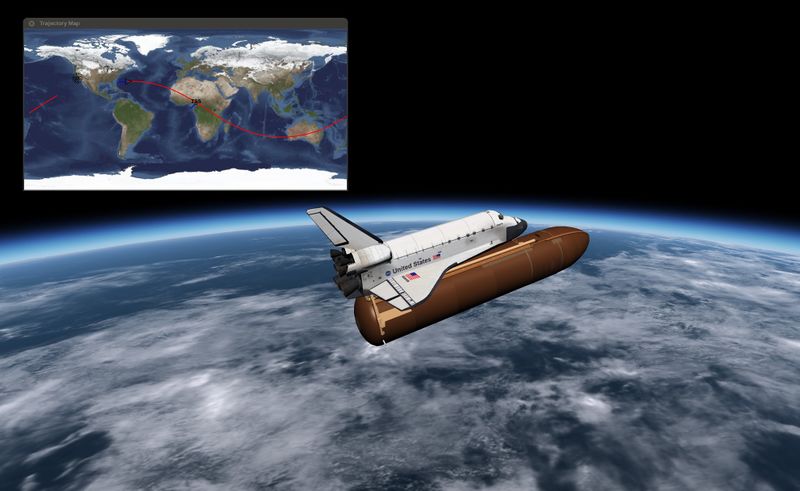
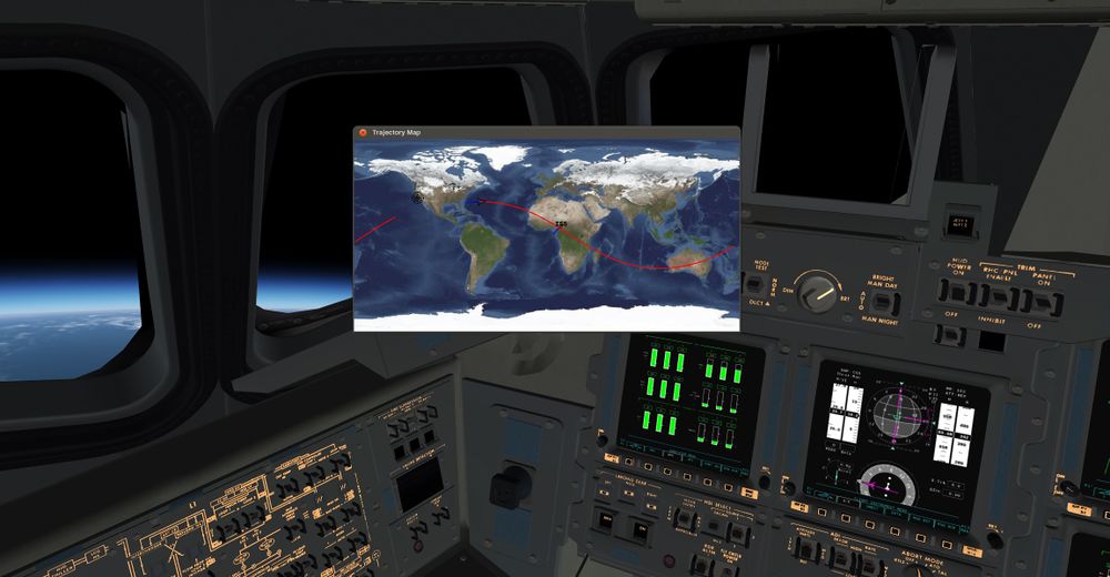
If you want to verify where you are, you can take a peek at the groundtrack map - open Mission Control -> Trajectory map and watch yourself departing from the Florida coast across the Atlantic Ocean. Your past groundtrack is shown in blue, whereas your projected future groundtrack is shown in red. You can see that we're going to cross central Africa.
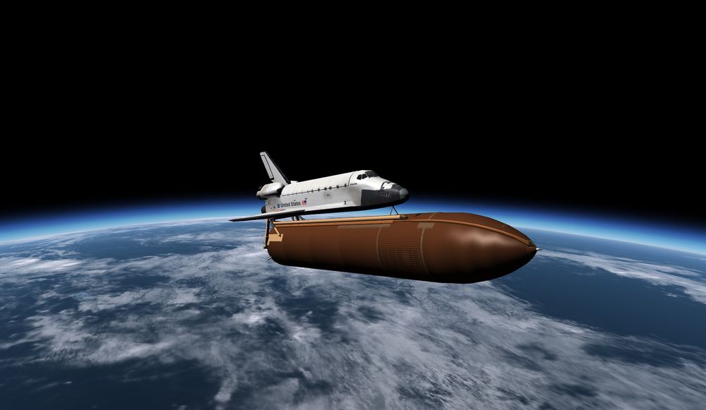
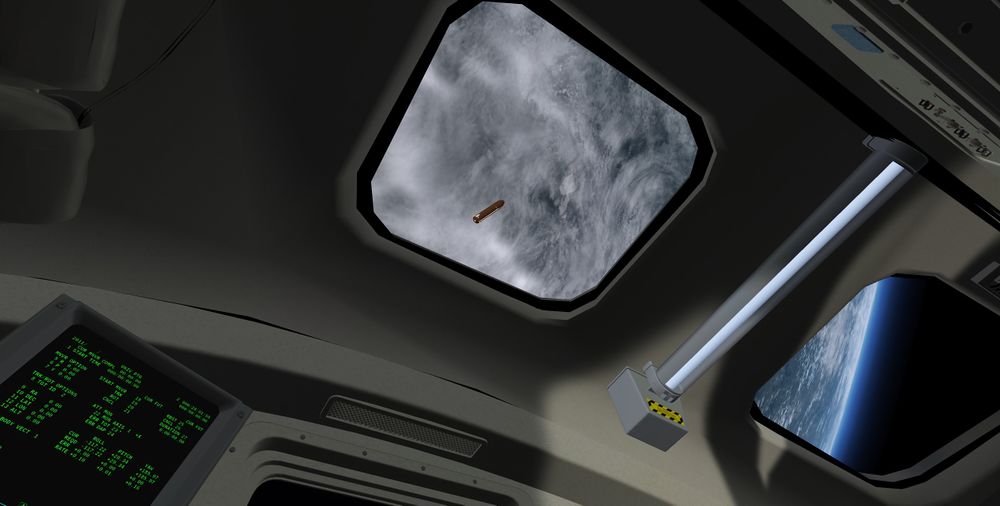
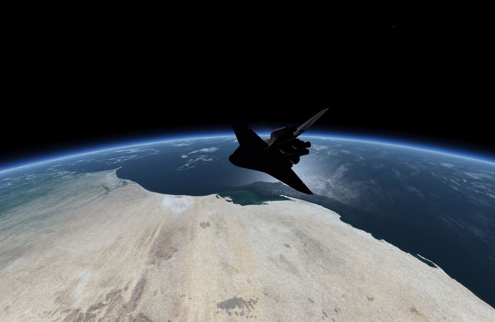
- Now switch to external view. You can see now that the external tank is still attached - remember, we started the simulation right after MECO (main engine cutoff). So the first thing we have to do is to get rid of the external tank.
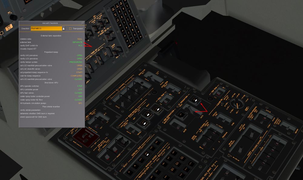
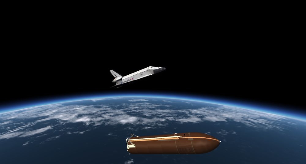
Open Help -> Aircraft Checklists and select the option Post MECO. You'll find that your first task is to null rotation rates (if the Shuttle is tumbling, the tank cannot be disconnected safely). This is already taken care off by starting in orbit, so feel free to press d to disconnect the tank (it looks quite pretty in external view).
The Shuttles RCS (reaction control system) thrusters will ignite automatically for three seconds to push the orbiter away from the tank, and then you should see a message that controls have been transferred to RCS. This means that your stick now controls the Shuttle's attitude. Make sure the stick is centered - if the stick configuration is hard to center, use the keypad instead - keeping all controls dead-centered is an operation you'll frequently need in spaceflight, and the 5 key does this very efficiently.
- To maneuver the Shuttle in orbit, the RCS thrusters are controlled by a number of DAPs (digital autopilots). If you look at the generic Flightgear HUD, you'll see a line with RCS ROT DAP-A in the upper left corner. This means that currently you control the RCS in rotation mode using the DAP-A configuration.
Each of the configurations has different characteristics (which can in fact be adjusted). DAP-A starts pre-configured to give you a rather maneuverable Shuttle with tight deadbands - easiest to learn maneuvering, but very wasteful as far as propellant is concerned. You can use ⇧ Shift + M to cycle through the different DAPs and m to cycle through rotational, translational and OMS thrust vectoring.
Stay with DAP-A for the moment. The next item of the checklist is to visually inspect the tank. This is done to see whether insulation foam has broken off during launch and possibly damaged the thermal protection tiles at the underbelly of the orbiter. We're left upwards from the tank. so push the stick (or 8 ) to bring the nose of the Shuttle down. If you monitor the rotation rates shown in the upper right corner of the FG native HUD, you'll see that they ramp up to some value and then remain constant - in this DAP, the stick controls the rate of attitude change. Rotate around till you can see the tank through the cockpit window (you'll have to push the nose all the way down such that it points towards Earth), then put the stick to neutral (or 5 ) and give the tank a good look.
In case you should ever find yourself tumbling out of control, remember that DAP-A is an attitude hold scheme - just select it, center controls and the flight control system will stabilize your attitude automatically.
Now bring the nose of the Shuttle back to the horizon.
- Next, we have to execute a propellant dump. The reason is that at this point, there are about 7000 lb of rocket fuel still trapped in the manifolds and lines feeding the main engines. They won't be a problem right now, but during entry they would shift the CoG of the spacecraft enough that it can't be stabilized. Since liquid hydrogen and oxygen make for an explosive mixture, we're going to dump them separately - the oxygen out of the engine nozzles, and the hydrogen through the fill/drain valves at the side of the craft. For this, we need to set a number of valves.
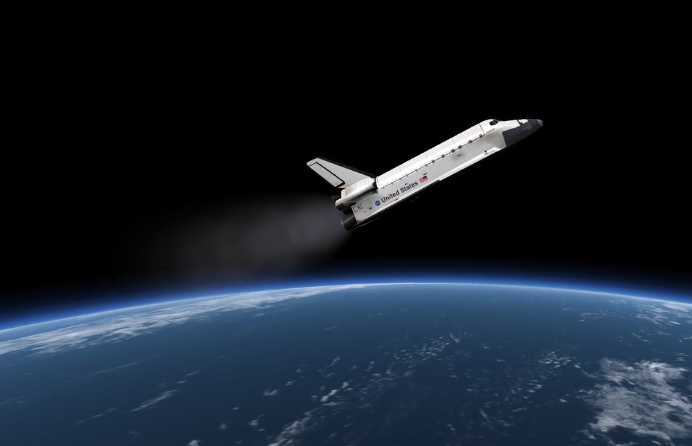
Open Space Shuttle -> Main Propulsion System and Space Shuttle -> Propellant Fill/Drain. Click on the manifold press LO2 valve (Main Propulsion System) and inboard and outboard LH2 valves (Fill/Drain), then do dump sequence start. High pressure helium is now pushed through the feedlines, expelling the remaining fuel overboard. Switch again to external view and observe the white cloud of liquid oxygen being vented through the engines.
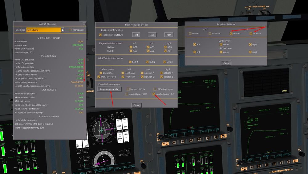
You can enjoy some nice visuals on the dump
It takes about two minutes till the sequence ends - close the LO2 manifold pressurization valve afterwards.
If you have monitored your velocity very carefully, you will have observed that the propellant dump actually made you some 9 ft/s faster.
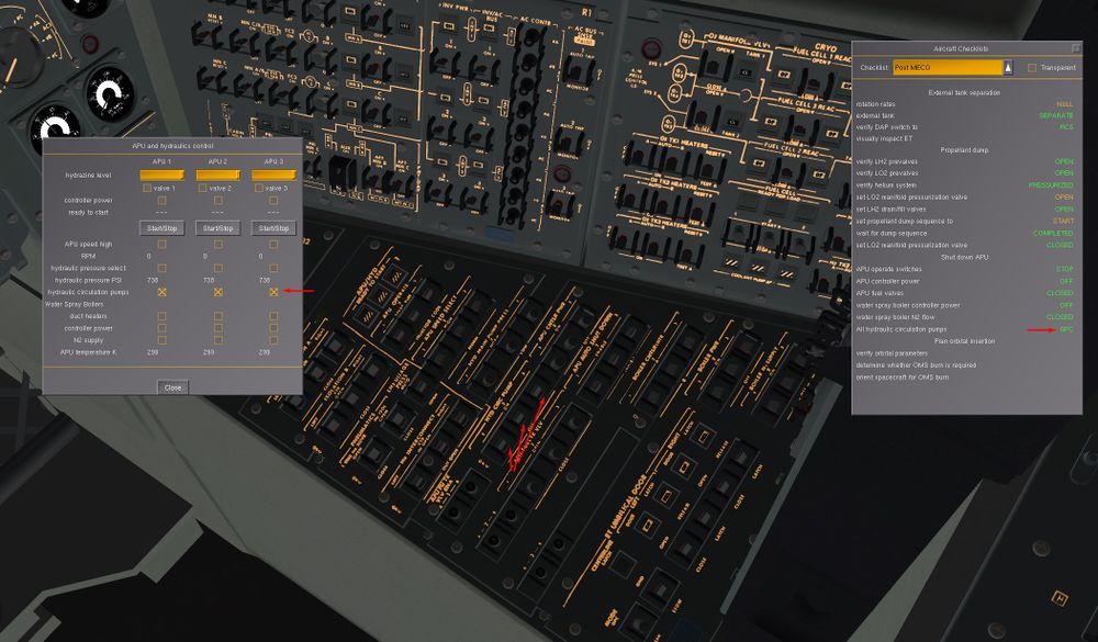
- Now would usually be the time to switch off the APU/hydraulics system. This would have been used to operate and gimbal the main engines during ascent, and since the hydrazine fuel for it is limited (and we're going to use it for entry again) we have to power it down while in orbit. In the event, the scenario started with APUs off.
Open the Space Shuttle -> APU and Hydraulics dialog anyway and switch one hydraulic circulation pump on - verify that hydraulic pressure is shown 2600 psi. In orbit, we need to slowly circulate fluid through the hydraulic system to prevent it from freezing up.
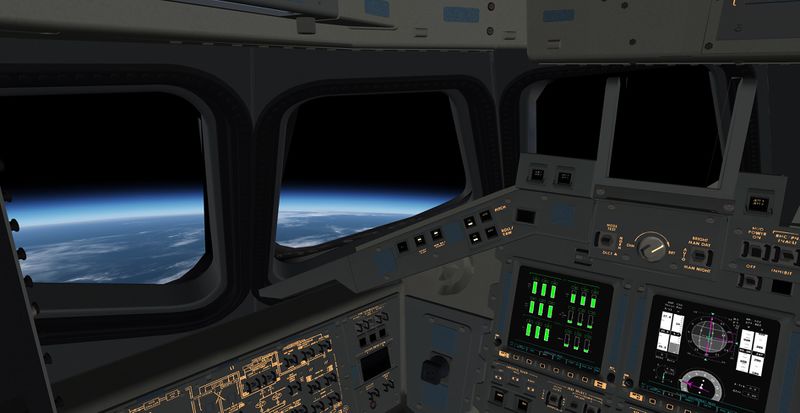
- We're done with post-MECO, so now we should take a look at orbital parameters and plan orbital insertion. The FG-native HUD has a few of those in the upper left (you should see an apoapsis, a periapsis and an inclincation value) but this isn't how the Shuttle normally displays them. So let's take a look at the display. Go into cockit view and zoom in on the active display. Press the left-most edgekey (button below the screen). This should take you to the MAIN MENU. Now press the button over which it reads DPS (data processing system).
You will now see a display of a trajectory named ASCENT TRAJ 2 and a number 103 in the upper left corner. This means that the display represents the OPS 103 mode of the computer. OPS 103 is control of the upper launch trajectory - which we don't need any more. We'll need to do an OPS transition.
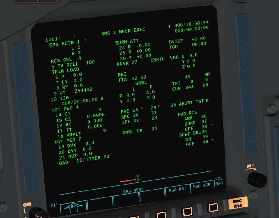
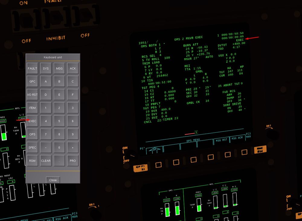
Open Data Processing System -> Keyboard. On the keyboard, press the sequence OPS 105 PRO (you can see how this is also displayed on the so-called scratch line of the DPS screen). The command stands for 'Operational Sequence 105 proceed' and should change the display to OMS 2 MNVR EXEC (OMS-2 maneuver execution).
On the right side, almost in the middle, you can see a small table with HA and HP and below a row CUR. The values represent current height of the apoapsis (in miles) and current height of the periapsis. HA CUR should be some 344, HP around 80. This means that you're not in a circular orbit yet - so we need to climb to the apoapsis and ignite the OMS engines there to circularize the orbit (and bring HP up to > 300).
For this, it'd be pretty useful to know when we reach the apoapsis so we can ignite engines just a bit before. This is shown in the center column - the value following TTA (time to apoapsis) tells you when you will arrive. Probably it's going to be some 30-40 minutes - a full orbit takes about 90 minutes, after MECO we started at the periapsis, so we expect the OMS burn 45 minutes after MECO.
Which means we have some time left before we need to prepare.
- The next checklist to complete is called Post OMS-1 burn. An OMS-1 burn would be used if we had launched with a heavy payload and the thrust from the main engines wouldn't be enough to reach a sufficiently high apoapsis. In this case, we'd ignite the OMS engines shortly after MECO. They way the scenario is set up, we don't need to do this, so we can work through the checklist right now.
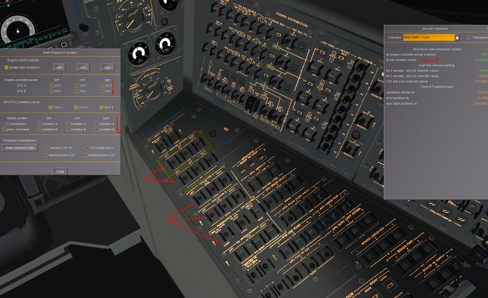
Open the Space Shuttle -> Main Propulsion System dialog. We need to shut down the MPS. First we remove power from all engine controllers - there's three engines, each with dual-redundant power supply for the controllers, so six switches in total. Next we need to disconnect the high pressure helium system from the engines - close all the eight isolation valves of the He system.
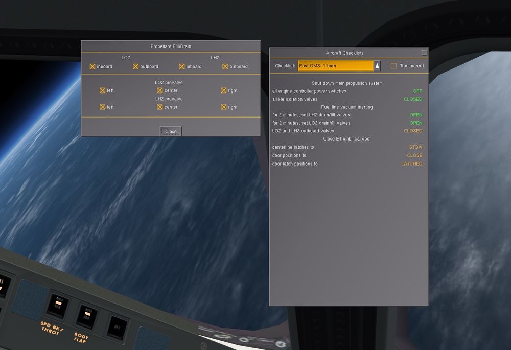
Now, there's still residuals of rocket fuel in the lines, so we open the Space Shuttle -> Propellant Fill/Drain dialog and open the LO2 and LH2 inboard and outboard valves for two minutes, then close them again. Now the MPS is ready for operations in vacuum.
At this point, the connection between external tank and main engines at the underbelly of the Shuttle is open - creating a huge gap in the thermal protection tiles should we enter the atmosphere. It'd be a good idea to close it now.
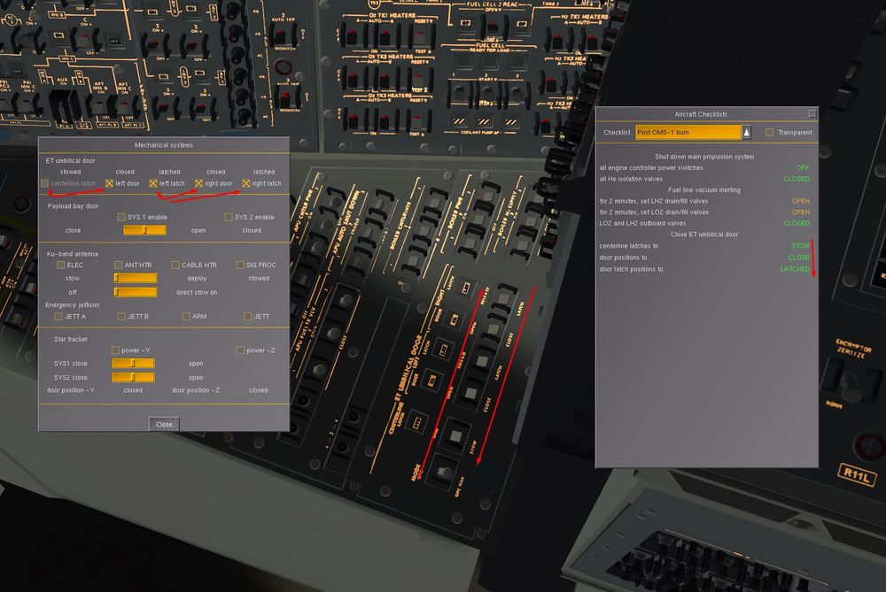
Open Space Shuttle -> Mechanical Systems. First put the centerline latches to 'stow' position, then operate left and right door switches till the talkback reads 'closed', then latch left and right door.
- If you haven't spent a lot of time searching for all the items, there should still be plenty of time left on the TTA counter. Let's use it to do some sightseeing.
If you've followed the instruction to point the nose of the Shuttle back to the horizon after inspecting the ET, you should now notice that it no longer points there - in fact, it should be pitched up well above the horizon now.
The reason is that we commanded attitude hold, but this is inertial attitude - a fixed direction in space. And as we orbit Earth, that fixed direction corresponds to any pitch value with respect to the horizon, dependent on where we are. However, sometimes we may want to assume an attitude relative to Earth. This is done by changing the Shuttle's control to LVLH (local vertical. local horizon).
Bring the Shuttle's nose back to the horizon, then open Space Shuttle -> Flight Controls and change the selection from INRTL (inertial attitude hold) to LVLH (local vertical, local horizon attitude hold). Now observe that as soon as you let go of the stick, the Shuttle fires thrusters to hold the current attitude and adjusts rotation rates to keep it as we orbit.
That done, let's take a look at the external tank. It's still there, orbiting with us - and you'll find it some way ahead and below.
It's easy to see why it should be below - after all, when separating we fired thrusters to push the Orbiter upward. It's less easy to see why that should bring the tank ahead of us - but this is a consequence of orbital mechanics, higher orbits are slower orbits, so by pushing the Shuttle upward, we also decelerate it relative to the tank.
Take your time sightseeing till TTA reads about 10 minutes (you should have just passed the Eastern coast of Africa by then).
- Now get back into cockpit and look at the MNVR EXEC display. We're going to enter a command for a prograde burn. That's done via PEG (powered explicit guidance) targets. In reality the crew would use PEG-4 (closed loop) targets, but we're going to use a PEG-7 target now.
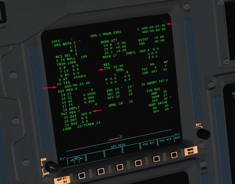
PEG-7 targets are direct velocity changes, and the prograde velocity is DVX. We want to increase it by, say, 400 ft/s, so we key in the sequence ITEM 19 + 400 EXEC. You should now see that the value of DVX has changed to 400.
For the time of ignition TIG, you can either let it blank and fire the OMS just before the Apogee, or specify a time to have a timer available
Our Mission Elapsed (MET) time is 25mn30sec (SPEC 1 PRO to change time from GMT to MET), and we want to do the burn at next Apogee in 26mn05s, shown right of TTA.
So time of burn is around 25+26= 51 mn in the mission ( for a perfect burn, we can push a bit before the Apogee)
To enter TIG, ITEM 10 + 0 + 0 +51 + 0 EXE
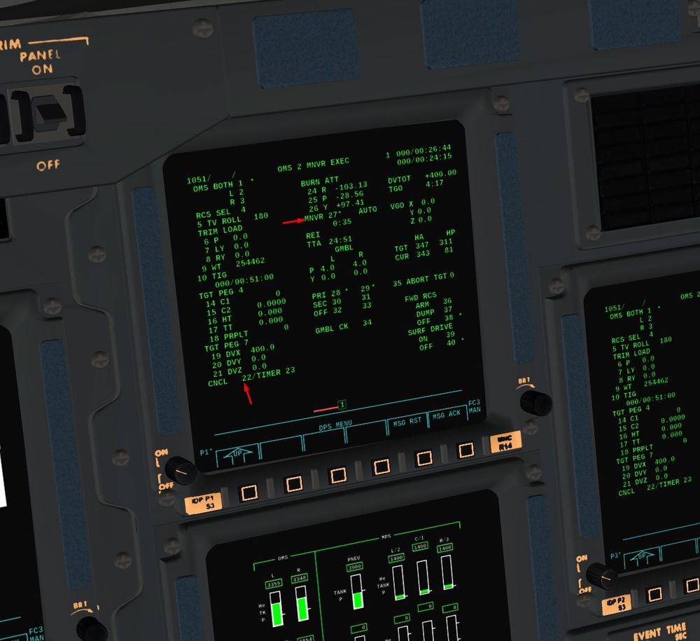
Before loading the burn plan, we need to know whether the OMS is actually operational, so we can do a gimbal check by using ITEM 34 EXEC. You'll see a * appear next to the item, indicating that the check is in progress, and if you see no errors, we're good to go.
With about minutes on TTA, use the sequence ITEM 22 EXEC to load the burn plan ( ITEM 23 EXE also if you entered a TIG to have the timer top right of the CRT). You'll now see that the values under BURN ATT change - this is the inertial attitude the Shuttle should assume when doing the burn. It changes, because as you go around Earth, the notion of what is prograde changes as well. If you don't know how to get the Shuttle into the required attitude, don't worry - flight controls will do it for you.
Right now, in the middle column, there should be a line MNVR 27 INRTL visible. This means that we are sill in Inertial DAP mode, so we need to open Space Shuttle -> Flight Controls and change the mode to AUTO - now we've handed over control of the Shuttle to the guidance computer.
Key in the sequence ITEM 27 EXEC - this instructs the computer to maneuver into burn attitude. Note that the burn is done hanging upside-down, i.e. the Shuttle will likely rotate around.
Watch the upper right corner of the display - as soon as you're in attitude, it'll start flashing 'EXEC' . Below you'll see DVTOT (the velocity change you're about to execute) and TGO (the expected time for the burn). If you've done everything correctly, TGO should be similar to TTA (actually, you want TGO about twice TTA). You can watch how the TGT HA and HP values change to more circular as you approach the apoapsis.
Now, two options depending or not you entered a TIG
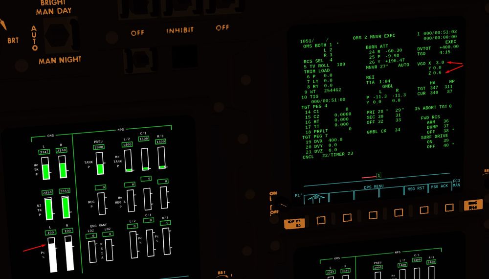
- On the DPS keyboard, press EXEC as soon as you see TTA about 2:30. You can now see TGO counting down, while VGO X and VGO Z below count up. At the same time, the values of current apoapsis and periapsis (HA CUR and HP CUR) will start to change and the periapsis will come up.
- If you entered a TIG, EXE will flash 15 sec prior to the burn and you will need also to press EXE on the keypad
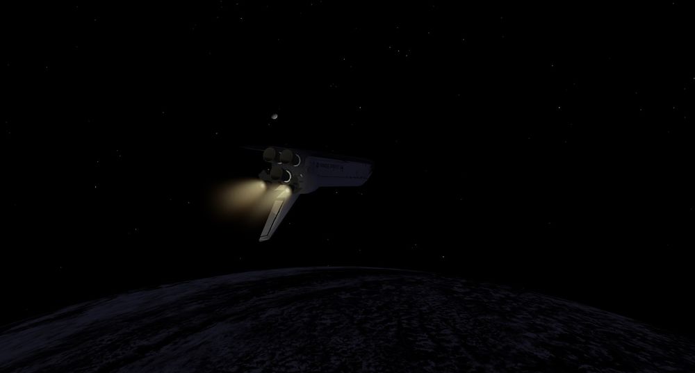
Take a moment to view the scene in outside view and take note how the engines really point at an angle, so the Shuttle vectors the thrust through it's center of gravity, with the thrust vector prograde. Inside the cockpit, the VGO X and VGO Z counters both pick up velocity changes for the same reasons, as they are accelerometers aligned with the Shuttle's body axes. For a correct burn attitude, you should observe VGO X being about six times VGO Z.
Change back into the cockpit and press SYS twice on the keyboard. This should get you to the GNC SYS SUMM 2 page (guidance and navigation, systems summary 2). In the upper left and right, you can monitor OMS fuel and oxidizer consumption as the burn progresses. This page is a so-called display (DISP) associated with an OPS sequence - many OPS sequences have such special functions associated with them.
When you're done, press RSM (resume - you can do this for every special display page you called from an OPS sequence main page) to return to OPS 105 and continue monitoring the burn. By now, you should be entering darkness (you're half an orbit away from launch, if you set the start time to morning, you should see the sun go down halfway around Earth).
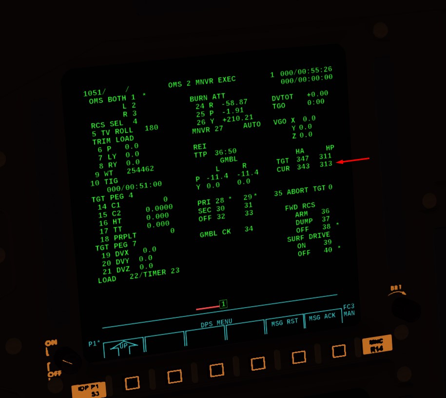
When the burn ends, you should be in a near-circular orbit - verify looking at HA and HP current.
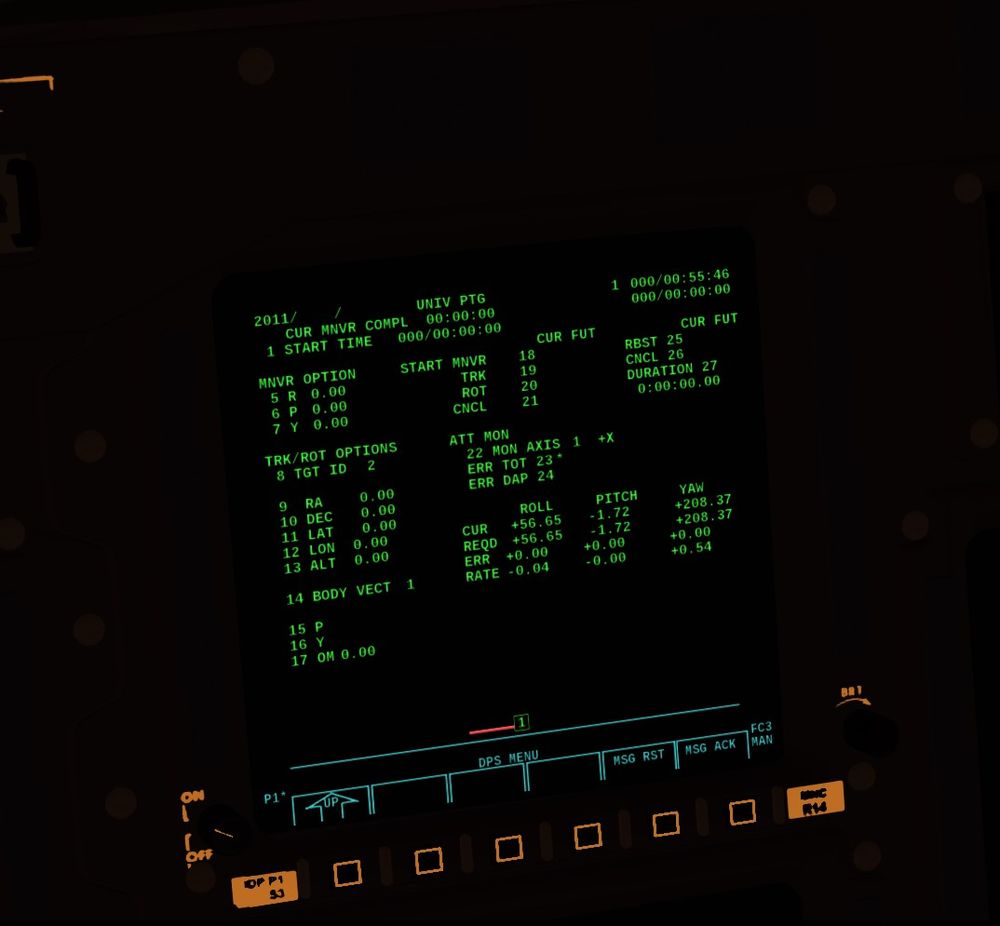
Press OPS 201 PRO to load the software used to manage orbital operations into the computers and watch the display change to UNIV PTG (universal pointing).
| Note For the last step about the GPC reconfiguration for Orbital configuration, you can use Advanced GPC in Space Shuttle In Game Options.
Then, you will have to fully reconfigure the GPC instead just pressing OPS 201 PRO
|
From this point on, the crew would get out of their seats and change from the bulky space suits into lighter garments and prepare the orbiter for the next days in space.
Congratulations, you're done with this tutorial!
Orbital housekeeping - a tutorial
(written for the devel version of Oct. 2017)
| Note You will have the opportunity in this topic to learn the basics of what happened after Orbit is circularized and OPS 2 Orbit guidance is loaded. It contains all the major post insertion items to cover before to begin the on orbit mission.
Once you feel confident with it, you can move on more advanced tutorial with more steps to do with Very Close to real operations and Checklists |
| Note This tutorial is for an up to date official Flightgear Space Shuttle Flight Manual. |
In this tutorial, you'll learn how to use the Shuttle's systems to operate in orbit - in particular how to do thermal management, how to deploy the Q-band antenna and to open the door and how to operate the automatic attitude control systems. In addition, you'll also learn how the software Caution and Warning System (CWS) operates and what the correct response to a CWS warning is.
- This tutorial requires that the Shuttle is inserted into a stable orbit and ready for orbital operations. See the tutorial Welcome to Space for how to do this.
If you want to start without completing the previous tutorial, you can take a shortcut and cheat by directly moving the Shuttle onto the desired orbit.
Start Flightgear with the commandline options
--aircraft=SpaceShuttle-orbit --lat=30.0 --lon=0.0 --heading=80 --timeofday=morning
Disconnect the external tank. Then maneuver the nose of the spacecraft down to the horizon such that in the external HUD the marker is at the zero line. Pause FG. Open the property browser Debug -> Browse Internal Properties. Using the property browser, set /position/altitude-ft to 2000000. Set /velocities/uBody-fps to 23295 and /velocities/wBody-fps to 140. Unpause - if you haven't made a typo, you should be in a near-circular 600 km orbit. Feel tree to fine-tune orbit by playing with the velocity components. Don't worry of the periapsis isn't perfect - just a stable orbit will do.
Do not under any circumstances try to set airspeed at this altitude - you will crash FG (in vacuum, IAS is zero for almost any airspeed you can think of, so specifying a non-zero IAS, you request a near-infinite inertial speed.
- Let's talk about temperatures in space, since much of what we will have to has to do with it. In the absence of an atmosphere, heat is transported by radiation towards and away from the Shuttle and by conduction inside the Shuttle.
The first major source of heat is the Sun - all sunward-facing surfaces will heat up (more so if they are dark). Thus, to heat a particular part of the Shuttle, we can turn it towards the Sun. The second source of radiative heat is Earth - while the radiated energy is substantially less, the effect is noticeable - night operations in a payload bay not facing Earth become quickly uncomfortable for astronauts.
The third class of heat sources is internal - the avionics bays of the Shuttle create a lot of heat, and as long as the APUs are running, they create even substantially more. If we do nothing, the heat generated by the avionics will eventually diffuse through the whole Orbiter, raise it's surface temperature and hence its radiated energy till there is an equilibrium. The problem is that heat conduction is so slow that the temperature in the bays will have risen so high that the avionic dies.
Thus, when we operate the Shuttle in orbit we want to accomplish two tasks - carry heat away from where it is produced internally and radiate it off into space, and prevent non-sunward facing parts of the Shuttle from freezing up.
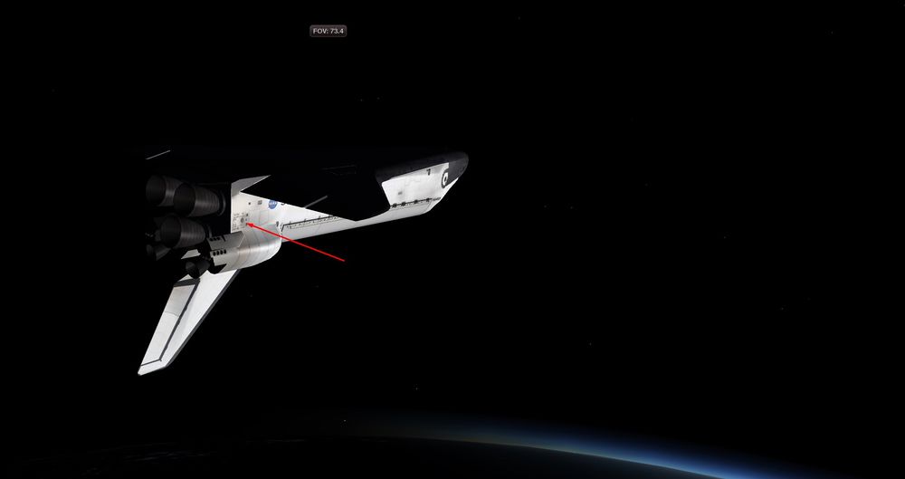
- Switch to the outside view and look towards the port aft fuselage - there's a small and faint exhaust plume of something.
This is one of the thermal management systems - the so-called Flash Evaporator. It uses the heat soaked up by vaporizing the on-board water storage to cool the Shuttle. The problem is that we can't keep it running - it'll use up all the water we have during a few hours. A similar device are the water spray boilers which each cool one APU - they have their own water tanks, and deplete at full load within an hour.
Thus, the default cooling device we have are the radiator panels which radiate heat into space. They're not super-efficient, but we can use them indefinitely. The problem is that they're attached to the inside of the payload bay doors, so we can't use them at the moment.
How does it all tie together? The avionics is cooled by water loops, they dump heat to the freon coolant loop which passes by all heat-producing systems in the Shuttle, freon circulates through both the flash evaporator and the radiator panels where it is cooled. Thus, heat generated by the avionics and other systems is either radiated away or vented away with the evaporated water, This takes care of cooling the parts that need cooling.
Heating the parts that could grow too cold is easier - the Shuttle comes with an array of thermostat-controlled heating elements, so by and large we just switch them on. Largely we need to be concerned with fuel freezing in the exhaust nozzles (potential explosion hazard) and hydraulics fluid freezing up and disabling the hydraulics system.
Finally, there's the effect on the whole fuselage - the material expends when heated and builds thermal stresses. These can for instance prevent us from operating the payload bay door - so we don't want to have an uneven heat buildup, and we can achieve this by attitude management, i.e. pointing cold surfaces towards the Sun.
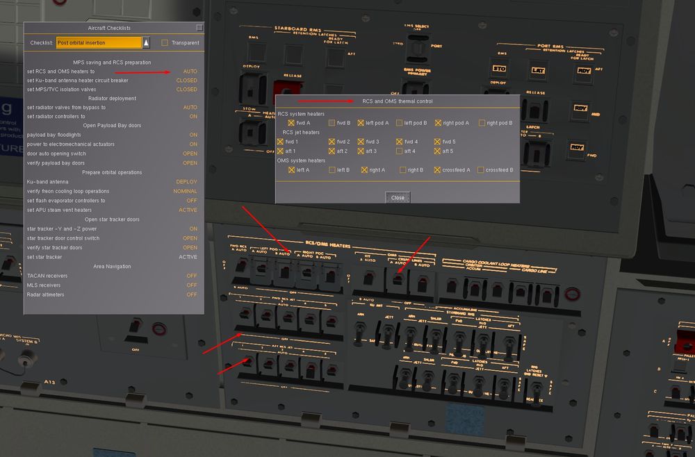
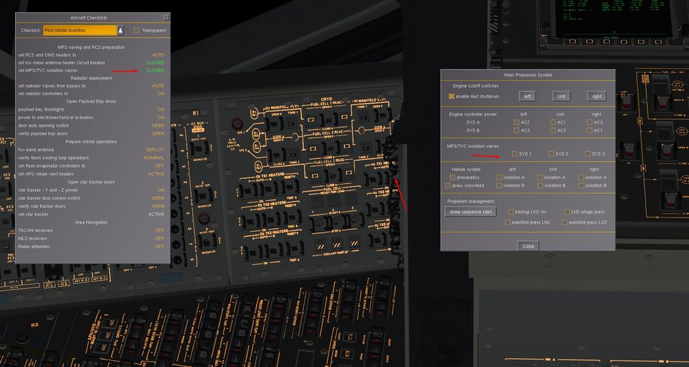
- Okay, let's get going. Open Help -> Aircraft Checklists and select Post orbital insertion. It instructs us to start with thermal management immediately. Open SpaceShuttle -> RCS and OMS thermal control and switch on all the heater elements for the thruster pods and fuel lines.
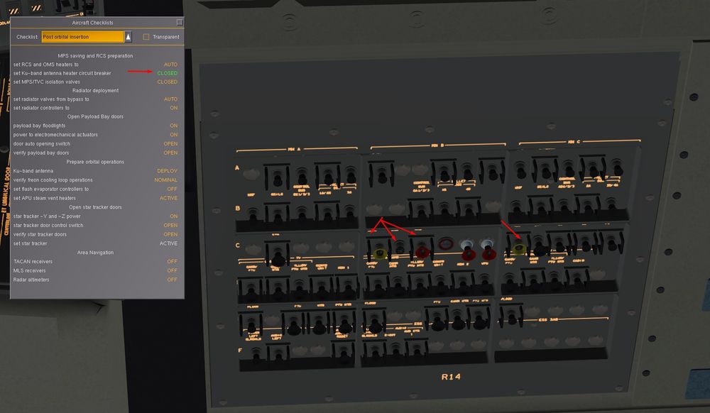
Next, open SpaceShuttle -> Mechanical Systems and switch on the antenna heater (ANT HTR) of the Ku-band antenna.
Finally, open SpaceShuttle -> Main Propulsion System and close the MPS/TVC isolation valves - we don't need hydraulical pressure to the engine actuators and gimbal systems now, the small pressure we have in the hydraulical system without firing up the APUs is best spent to circulate fluid through the systems we will need during entry.
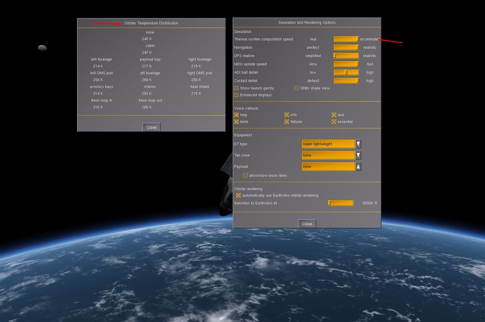
- Next, open SpaceShuttle -> Active Thermal Control System and SpaceShuttle -> Orbiter Temperature Distribution. The latter will show you the current temperature of various parts of the Orbiter, in particular you'll see relatively hot avionics bays and in-freon loop temperature. Thermal inertia of the Shuttle is high, so there won't be quick adjustment of sun-facing surfaces, it takes a few hours for the spacecraft to cool after launch.
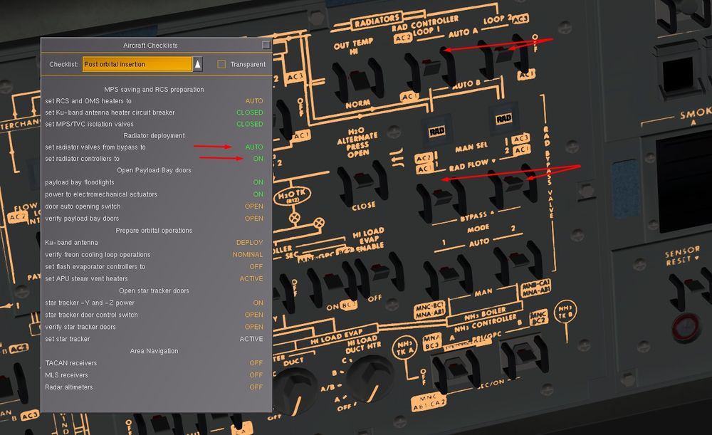
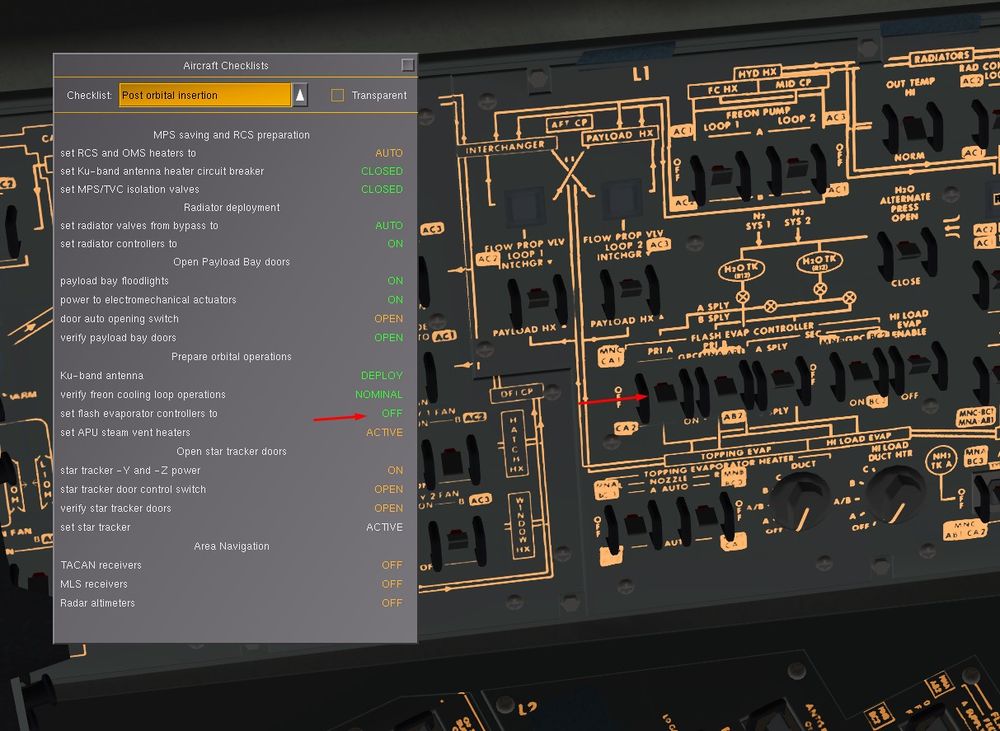
We're now going to change the freon cooling from flash evaporator to radiator panels. Switch the flow bypass loops off. Then switch the radiator loop controllers on. Freon is now allowed to circulate through the radiator panels inside the payload bay door. This won't be effective just yet as the door is still closed, so we leave the flash evaporator on.
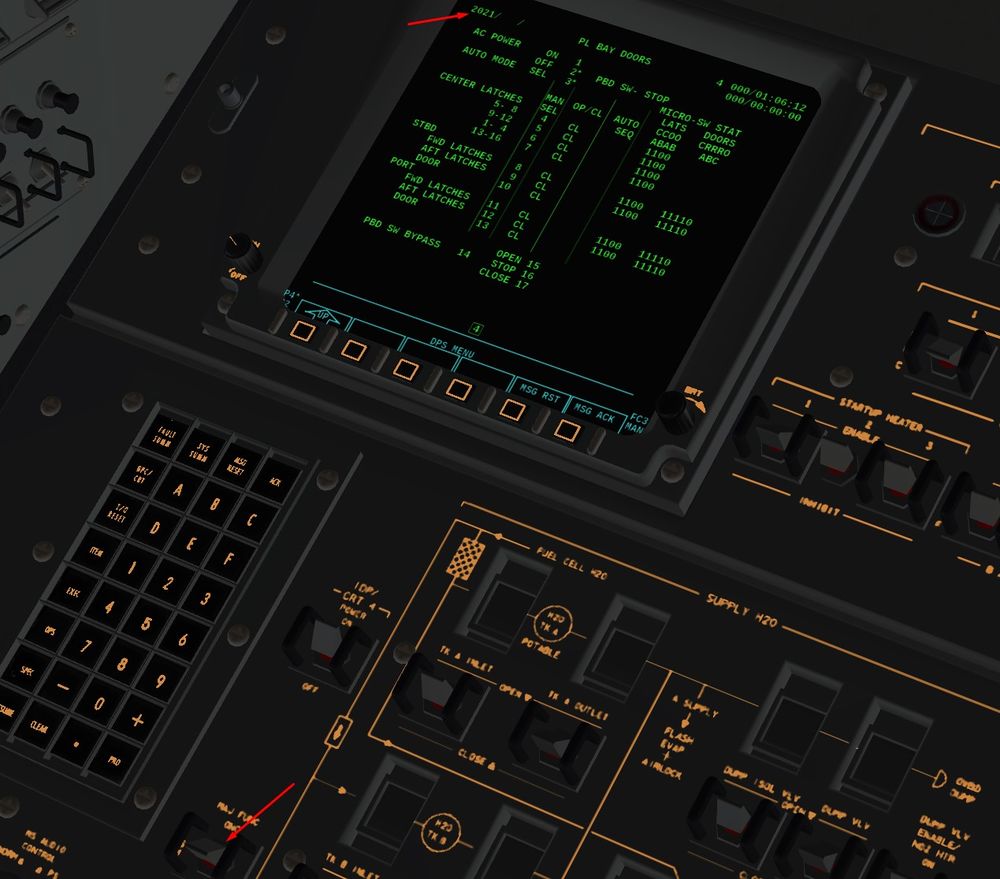
- We're now going to open the payload bay doors. There's a simple mechanical switch to do it, but let's get to know the avionics better. Go to OPS 201 (OPS 201 PRO)with the Major Function switch to SM ( System Management). Then call up the specialist function for payload bay door management (SPEC 63 PRO)
You can also so go directly to that page by OPS 202 PRO.
You should see this:
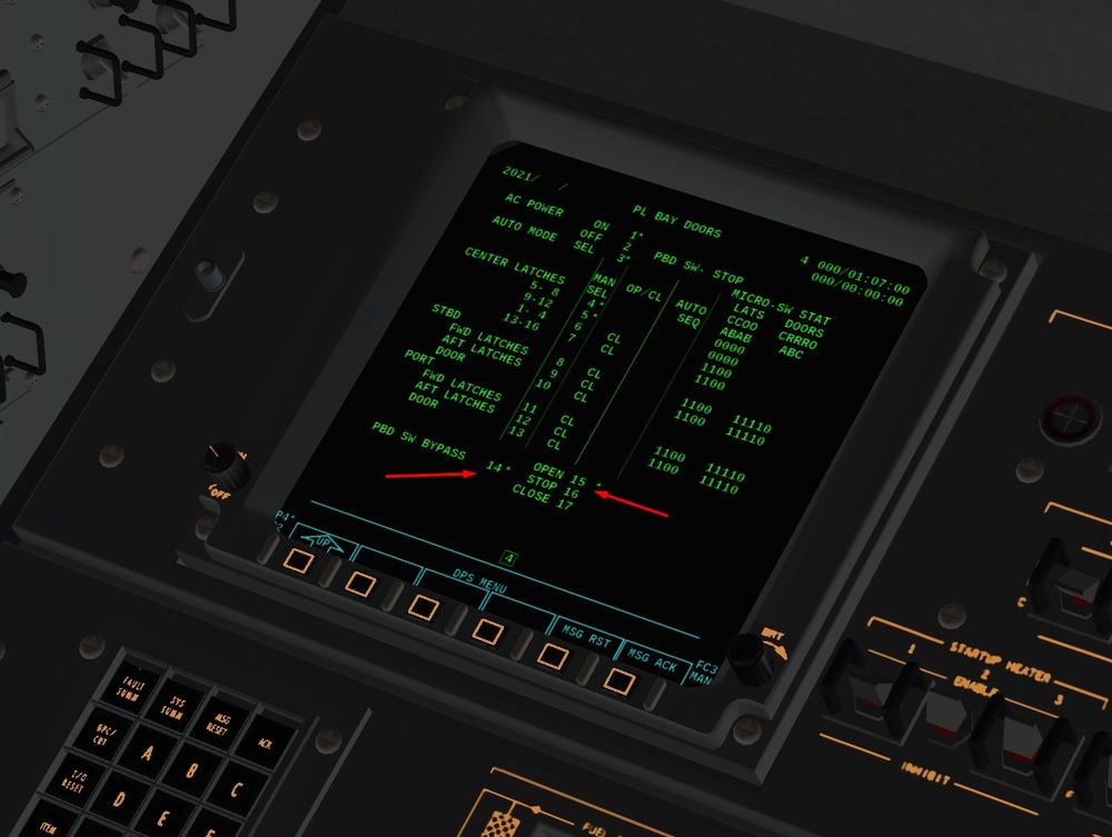
First we need to power the system (ITEM 1 EXEC). Verify that automatic opening mode is selected (a * is behind item 3). Transfer control from the mechanical switch to the software (ITEM 14 EXEC) and command the doors open (ITEM 15 EXEC).
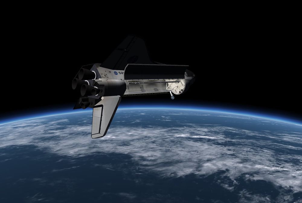
You can watch the status changes of the various latches holding the doors together as the automatic opening program operates them in sequence. Eventually the doors will also be moved. Feel free to watch from external view - the whole sequence takes some four minutes.
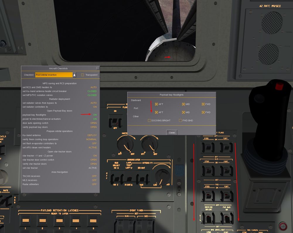
If it happens to be dark, you can use the floodlights from Payload Operations -> Payload bay floodlights - they take about a minute to ramp up to full power.
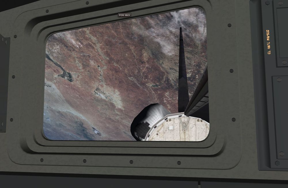
Admire that view, how can we be fed up with that deskview
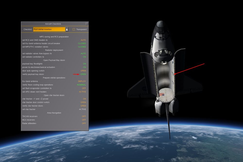
Check that the doors are well opened before moving on
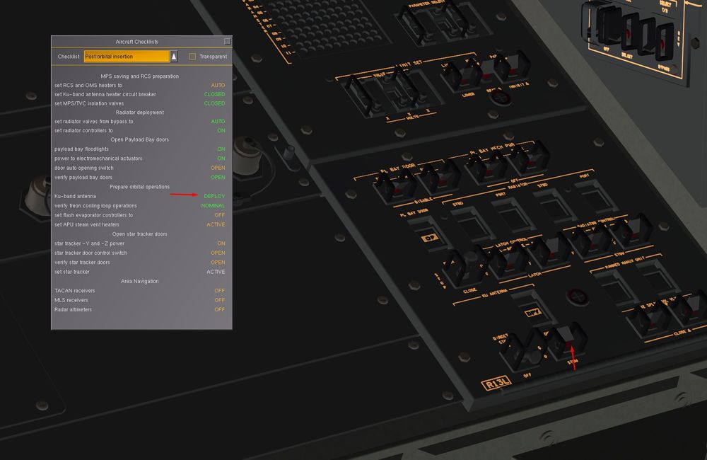
Now that the doors are opened, you can deploy the Ku Band Antenna, main device to communicate with MCC, to receive upload (Burn solution, State Vector Update,...) and download to MCC some Shuttle infos. Also later, it will serve as a Close Range Active Rendez Vous Radar for ISS or objects tracking.
Then, you can switch off the flash evaporator in the Active Thermal Control - switch off the 'primary A' controller and the 'hi load evap enable' option.
Then watch the freon loop in and out temperatures for a while to verify that the radiator coolant loop has indeed taken over the cooling (if there's no difference between freon loop in and out temperatures, the loop isn't being cooled). Evap Out is your main variable to monitor here. It indicates Freon Temperature after being cooled by Radiators and FES ( below 50 °F should be good)
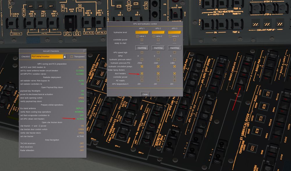
Some more thermal management with the APU Boilers that cool Hydraulic Fluids and Oil from APU's Gearbox when they are in use. We have to heat the Steam Vents during Orbit Operations to avoid Water Freezing.
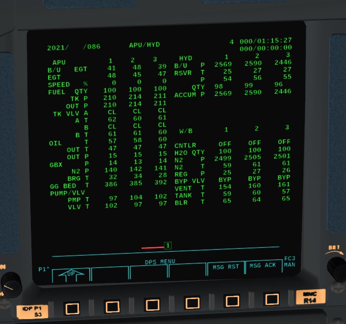
- the real Shuttle doesn't have a dropdown menu to get the temperature distribution - so how does one check whether the thermal management works then? That's what Systems Management (SM) functions are for. Key in SPEC 86 PRO and look at this
This is the APU/hydraulics overview panel. On the left hand side, there are three columns of numbers, referring to the APUs 1,2 and 3. Whenever there is a T in a row, you're looking at a temperature reading. For instance TK VLV A T means 'temperature reading at tank valve A', GG BED T is the gas-generator bed temperature of the APUs (in the sample picture above, APU 2 is actually running and has a high gas generator bed temperature). With this and similar screens, you can check many temperature readings throughout the Shuttle.
Use RSM to get back to the OPS 201 page.
Then, we will activate the Star Trackers ( 2 devices). Very useful optical devices that allow IMU alignement using known inertial position of Stars and can track ISS further than the Ku Antenna can do.
To verify the good behavior of the ST, let's switch to the Star Tracker DPS page.
For that, in major function GNC, SPEC 22 PRO Item 3 and 4 should be active ( star right of them) indicating that each Star Trackers have a star in sight and can be used to align IMU
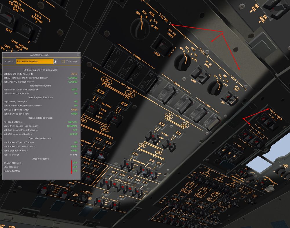
Final Step, to decrease power consumption, we turn off all the Navigation means that we need for abort, entry and landing ( TACAN, MLS, Radio Altimeters)
They will be activated again for entry.
Well done, you are fully configured in Orbit and you can safely rest.
Now, you can tackle a harder challenge with Flying the Shuttle - Launch And Post Insertion Advanced or just practice some orbital changes, ISS rendez vous or RMS usage.
Let's go a bit further before ending this tutorial with some Thermal Management and Auto pilot manoeuver to keep the Orbiter in a Good Thermal Equilibrium.
- Let's try some thermal management. If you have started the tutorial in the morning, the Sun should be up (otherwise select 'Noon' in Environment -> Time Settings).
Switch SpaceShuttle ->FlightControls to INRTL and point the nose of the Shuttle directly at the Sun. Open SpaceShuttle -> Orbiter Temperature Distribution.
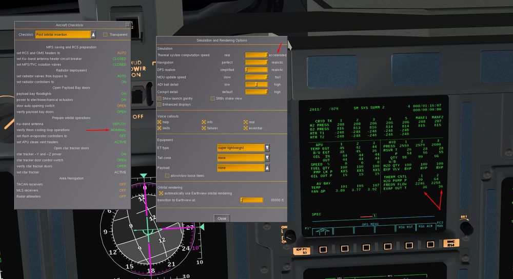
In reality, it'd take a while till we see what happens - one or two hours perhaps. But this is a simulation. Open SpaceShuttle -> Simulation Options and switch Thermal system computation speed to 'accelerated'. This increases radiation and heat conduction by a factor of 100 - and you can see in a few minutes what would take hours in reality.
Within a minute or so, you can see the nose being much warmer than the payload bay and the orbiter sides. So, by pointing the Shuttle suitably, we can ideed heat and cool the various surfaces.
(Don't ever try this when a cooling loop is off, or you will fry the avionics before you can remove the acceleration).
- If you wait somewhat longer, you will notice that the Shuttle in inertial attitude hold mode actually remains pointed at the Sun. The reason is that the Sun position in the sky, when considered with respect to the background stars, varies only due to the yearly motion of Earth - so at the timescale of a Shuttle mission, it changes imperceptibly slow.
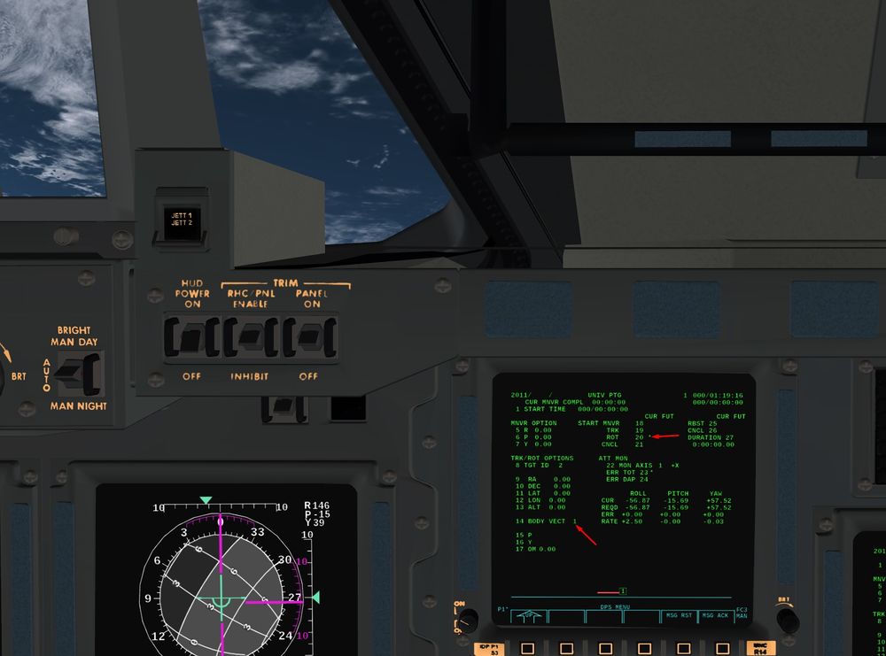
However, the Shuttle also has automatic routines for attitude control. Maneuver such that the payload bay points towards the Sun, then bring up the UNIV PTG display OPS 201 PRO if it is not already there. In the lower right, you can see current inertial attitude and errors.
The things we can do under automatic control are MNVR (maneuver, item 18), TRK (track, item 19) and ROT (rotate, item 20) - whereas CNCL (cancel, item 21) ends all maneuvering.
Maneuver targets are specified in the upper left (items 5,6 and 7) and executing MNVR brings the Shuttle automatically into the commanded attitude. For thermal control, the other two are more interesting. Let's start with ROT - this commands a rotation around the current axis.
Let's try this - maneuver the Shuttle such that the payload bay roughly points sunward, then activate the ROT mode (ITEM 20 EXEC).
- If you have followed the instructions to the letter, you should now see a flashing message at the bottom of the screen which reads 'SEL AUTO' whereas the Shuttle does not maneuver in any way. The message comes from the Caution and Warning System (CWS) and is supposed to remind us that we need to change from INRTL to AUTO before commanding automated maneuvers.
Okay - let's do that.
Now - how to get rid of the message? Press ACK (acknowledge) on the keypad, and the message stops flashing. Good - now we can inspect it properly. Press ACK again to see whether there was perhaps a second message underneath it. That's not the case, so since we understood it, we'd like it to go away - press MSG (this reads MSG RESET on the 3d-cockpit keypads) to remove the message.
Well, maybe that was premature - what if you accidentially remove an important message too quickly? Don't worry, it's all still there - press FAULT (or FAULT SUMM ) to get the fault summary page. Here is a record of the last 15 messages along with a timestamp and some more technical information.
Note that CWS does not contain any emergency-level messages - these are far too important to be entrusted to the software, so they have hardware systems which illuminate warning lights and sound klaxons if necessary.
- Now go back to the UNIV PTG screen (press RSM). You should see from the lower right attitude that you're indeed rolling, and a look outside should confirm this. That's neat - the Shuttle now operates like a grill - both payload bay, sides and heat shield get equal exposure to sunlight and hence stay equally warm.
Now check rotation rate - it should be some 2.5 degrees/sec. That's quite fast. How to get it slower? For this, we can either switch to a different DAP or change DAP characteristics.
This rotation around X Body Axis is used a lot for Thermal repartition in Orbit OPS, called the " Barbecue", let you guess why
(To be continued...)
Proximity operations
(written for the devel version of March 2016)
| Note This tutorial is for an older version and obsoleted by the official Flightgear Space Shuttle Flight Manual. |
In this tutorial, you'll learn about the navigation during the late phase of an approaching and docking maneuver. As of March 2016, FG does not yet support simulating fully orbiting objects at arbitrary distance, so ISS is just instanced ad hoc close to the Shuttle, thus there's only the capability to simulate the last few kilometers.
Part of the idea of this tutorial is also to allow testing of the relevant features by a wider audience as the underlying code is fairly complex.
- start FG with the options
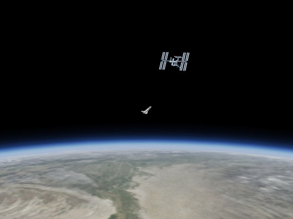
--aircraft=SpaceShuttle-ISS --lat=51.0 --lon=30.0 --heading=90.0 --timeofday=morningto find yourself trailing ISS by a few hundred meters in a stable orbit of about 320 km altitude. The Shuttle is initialized in OPS 201 with payload bay door open and Ku-antenna deployed and ready to maneuver.
Note: Occasionally it seems to happen that ISS is initialized but disappears immediately, leaving a note in the console that it passed the distance cut. This seems to be an initialization timing issue which I haven't been able to track down yet. Re-starting usually helped.
We want to maneuver the docking collar of the Shuttle (facing upwards, or into the -z direction of the orbiter, located in the payload bay right behind the rear flightdeck windows) to the ISS docking port (only one of those is supported right now). There's a number of effects which makes this complicated.
First, there's orbital mechanics. By not being in the same position as ISS, we're not in the same orbit, and every time we maneuver the Shuttle we actually change orbit. For instance, as soon as we ignite thrusters to get closer to the station we also raise apoapsis and will hence tend to climb above the station. At small distances of a few kilometers, the effects are small but still noticeable.
Second, there's genuine drift - there are small residual forces pushing both the Shuttle and ISS around even with no thrusters ignited, for instance every time waste water is vented, or when the flash evaporator is running, small propulsive forces act. Several of these forces are implemented in the simulation.
Third, there is numerical drift due to the fact that the space station position update is computed at framerate while the Shuttle is computed at FDM rate, which also leads to tiny mismatches comparable with the genuine drift effects.
Finally, there is thruster cross coupling - usually commanding any Shuttle motion, either rotation around an axis or translation along an axis, also causes (weaker) rotations and translations involving other axes. Due to the arrangement of the thrusters, there is no 'clean' way to accelerate the Shuttle only forward without causing e.g. a rotation around the y-axis. Rate-controlled DAPs can to some degree tame these effects, but not perfectly.
The result is a need to fine-adjust the motion right until the docking moment - it's practically impossible to 'fix' first the x-axis and then the y-axis, because y-axis corrections will feed back into the x-axis, and so will drifts.
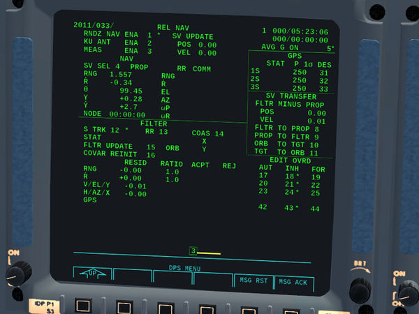
- but first, let's find out where we are. Key in SPEC 33 PRO on a DPS page to get to the REL NAV screen. The screen will be mostly blank at first, and that's because rendezvous navigation is disabled, so follow up with ITEM 1 EXEC. You should get to see a column of numbers appear below SV SEL similar to this:
The meaning of these is
RNG: the remaining range to target (in thousand feet), Rdot: the approach rate, θ: the orientation relative to the angular momentum axis of the target (assumed to be the docking axis), Y: the offset along the docking axis and Ydot: the approach rate along the docking axis.
Now, if you're at rest relative to ISS, Rdot and Ydot are zero. As long as you're approaching, Rdot is smaller than zero, if it is larger than zero range increases. If you're properly oriented to dock, θ is zero. If you are on the docking axis, RNG = Y. To successfully dock, you need to get close to RNG = Y = 0 and θ = 0.
- Now let us consider a more interesting question - how does the Shuttle actually know these numbers?
The answer is that it really doesn't - the orbital parameters of the rendezvous target have been i-loaded into the memory and are constantly numerically updated by the GPCs. The Space Shuttle's own state vector (position and velocity) is likewise numerically computed forward ('propagated'). That's done based on acceleration measurements by the inertial measurement units (IMUs) as well as information uplinked from ground tracking and supplied by the on-board GPS units.
The numbers shown are hence computed based on what the Shuttle's GNC believes to be true, not on what is true. But neither IMU measurements nor the models used to propagate the state are perfect, so there's margin for error here.
Note: If that's too much to handle, you can switch to 'perfect navigation' in the Shuttle simulation options and then the numbers will be true). In this case you can skip much of the following.
It would be stupid to rely on the fact that propagated state vector work to an accuracy of a few centimeters - but the Shuttle can also measure parts of the parameters, for instance the ku-antenna can be used as a radar ranging device. The star tracker can be used to monitor the apparent motion of the target across the sky as the Shuttle moves, and so can the COAS system. From all of these, constraints for the difference between Shuttle and ISS state vectors can be derived, which are available as filters.
(Note that the radar ranger can do nothing to fix absolute errors in the position of either the Shuttle or ISS, but it can make sure the docking information is more or less correct).
- To enable the radar ranger, we first need to do ITEM 2 EXEC - this allows forwarding of the rendezvous navigation data to the antenna manager such that the antenna can be pointed into the right direction.
Usually the antenna is used for communication with the TDRS network though, so we also need to change the mode. Open Space Shuttle -> Ku-antenna and select RDR PASSIVE instead of COMM - this instructs the GPC to use the system as ranging device. Leave the final setting at GPC as we don't want to manually point the antenna.
(This of course implies that we might drop the link to mission control - there is still the S-band system capable of linking to ground station, but only if there is line of sight, so while the TDRS network has a com outage of perhaps 6% over a typical orbit, this value will now grow dramatically - that'd be the main reason to not use the ranging radar for proximity).
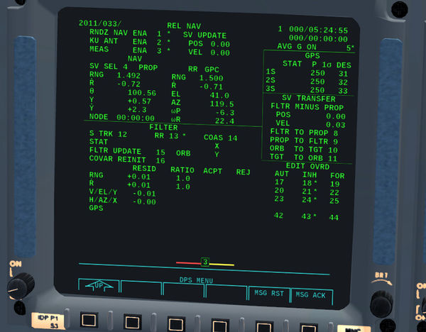
It takes a few seconds for the antenna to move from tracking a TDRS satellite into the new position, then a new column of numbers appears right of our approach parameter set:
Range and approach rate are the same, but the rest is different. The display shows (inertial) azimuth and elevation of the antenna pointing vector as well as the change rates.
Why doesn't the antenna show the much more useful Y and Ydot? Because a ranging radar can't measure them directly - the radar ranging column shows only parameters that are directly measurable. They're still useful though, because the software can deduce from the measurements what the most likely corrections to the state vectors are.
It may happen (as in the display above) that propagated range and measured range are not the same - in which case we know that there's an inaccuracy.
Look at the RESID column in the lower part of the screen - this indicates the current value of filtered minus propagated parameter, If the residuals are zero, the current filter agrees with the propagated state, if they're nonzero the propagated state vector does not agree with the filter.
- Let's now use the radar ranging as filter and enter ITEM 13 EXEC to use the radar rather than the less accurate star tracker for the filter.
Well, nothing much seems to be happening. That'd be because we're still displaying the propagated rather than the filtered state - so use ITEM 4 EXEC to switch the display to the filtered state vector - that should give you a much more accurate picture for the approach parameters.
(You can also do ITEM 8 EXEC to replace the propagated with the filtered state vector, but that doesn't add anything to the rendezvous accuracy - instead it might introduce an absolute error because the filtered state can only correct relative differences between Shuttle and target).
Note: The true state vector isn't shown anywhere on this display because it is not known to the avionics. Getting residuals of zero just indicates that the filter agrees with the propagated state - that may be because the propagated state happens to be correct, or because both filter and propagated state go wrong the same way (if you have a poor filter, it will default to the propagated state). Thus, you can't ever assume you're safe in flying by the numbers - you need to take a look out and verify that the instrument reading is plausible. After all, the visibility will always be good.
- Having fixed the approach parameters, we can now proceed to actually maneuver.
Since the ku-antenna is eminently useful for ranging, we want to keep it pointed at the station. Thus, the recommended approach position is along the orbiter's -Z axis (i.e. payload bay facing towards the station) such that the orbiter fuselage can't block the antenna.
Unfortunately, that means we don't see ISS at all looking out of the front cockpit window. Well - no problem, we just do this from the payload specialist station and look through the upwards windows. In the real Shuttle, there's hand controllers installed for just this purpose.
Okay - but there's now another problem. Looking along the -Z axis, all notions of yaw, pitch and roll are twisted from what you're used to. The basic hand-eye coordination telling you to push the stick if you want to pitch down does no longer work. Having to constantly re-think what controls to move in something as critical as a docking operation surely is a bad idea?
Luckily the Shuttle constructors took care of this. Open SpaceShuttle -> Flight controls and switch sense to -Z - now all control inputs will work as you're used to as long as you look along the -Z axis and you don't need to re-train your reflexes.
Use RCS ROT DAP-A to adjust attitude early on, then proceed to RCS TRANS ATT HOLD to move the Shuttle around. Once you're close to ISS, in order to not fry it with your thrusters, use RCS TRANS LOW-Z ATT HOLD. This will give you a factor 12 reduction in thrust along the Z direction, so anticipate that you can't decelerate quickly!
- The key to a good approach is patience.
Anticipate the movement of the Shuttle. Every motion you initiate has to be explicitly countered. In the rotational axis, the attitude hold will do this for you - in the translational axis you have to do it yourself (for the time being...).
Give small inputs, keep rotation and translation rates slow - this will give you time to react and correct, and it will minimize cross coupling effects. Remember to always center controls if you're not adding thrust. The keyboard is your friend.
Initiate a burst of thrust, then wait for 20 second to gauge the effect visually. Cross-check with the parameters on SPEC 33. Then initiate the next motion. Don't fire a thruster before you are sure you have observed the effect of the last firing.
The one thing you have is time - so correct one axis, then turn to the next till it looks good, then to the next - don't add to your workload by trying to maneuver in six degrees of freedom all at once.
Maneuver first close to ISS and null rates as good as possible. Then maneuver onto the docking axis (remember, here RNG = Y). Then try to approach along the docking axis till Y and RNG drop to zero.
(Currently you can't crash into ISS - if you managed to get within 40 cm of the docking collar in the correct attitude, it'll work).
If you're successful, you should connect with ISS in about the following attitude:
Don't try to ignite thrusters while docked - you will yank ISS around... When you're done, use Ctrl+U to undock and separate slowly before igniting any thrusters.
