Procedural texturing
| The FlightGear forum has a subforum related to: Effects & Shaders |
| Rendering |
|---|
|
Rendering Pipeline |
|
Effects and Shaders |
|
Ongoing Efforts |
|
Standalone Tools |
|
IPC/Networking |
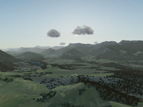
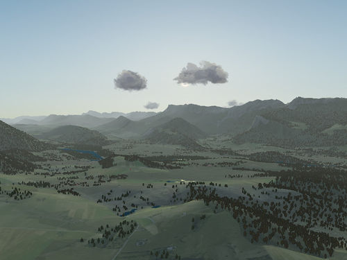
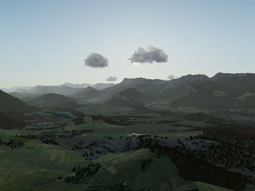
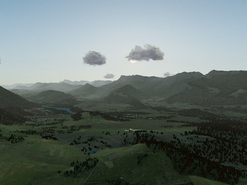
Procedural texturing is a set of techniques where the color of a pixel is not determined by a texture image but fully or partially by evaluating a mathematical function. This article describes why procedural texturing is useful, what it can and can't do and how it is used and configured in FlightGear.
The terrain texturing challenge
The FlightGear terrain is segmented into different landclasses (Urban, Ocean, Glacier, ShrubCover,...) which describe what the terrain at a location is like. In the default texturing scheme, the file materials.xml is used to describe (among other things) what texture sheet is mapped onto a given landclass.
A typical terrain texture sheet has 512x512 pixels and is mapped onto a 2000m x 2000m sized area, which means that each pixel covers a 4m x 4m area in unsloped terrain. For the sake of the argument, assume the texture has a size of 300 kB in compressed form which expands to about 1 MB in the GPU memory after mipmapping.
The optimal distance to view the texture is when every texture pixel corresponds to a pixel on the screen, as then the maximum possible detail of the texture is exploited. Assuming a 60 deg field of view looking straight down onto the texture, that distance is about 2500 m.
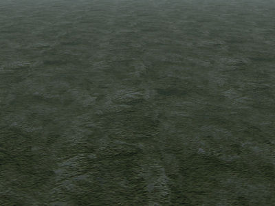
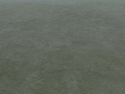
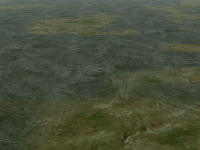
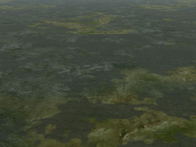
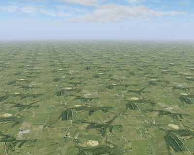
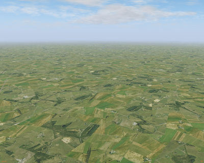
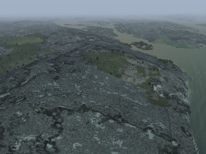
If the texture is seem from a much larger distance, it does not large enough to cover the terrain, and hence it is automatically repeated. From about 3 times the optimal distance, this repetition creates a visually rather pronounced pattern which is referred to as tiling:
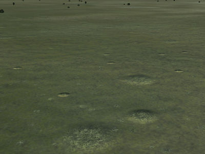
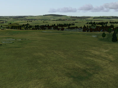
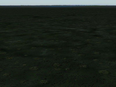
If the texture is seen from a much smaller distance, a single texture pixel covers multiple screen pixels, which makes the terrain look coarse-grained and unrealistic:
A third problem occurs because the boundaries of the landclasses are vector data, i.e. they appear as unnaturally sharp division lines between different textures.
Thus, the main challenges for realistic terrain texturing can be summarized as the three areas
- tiling
- resolution
- boundaries
Addressing the challenges
Tiling and resolution are correlated problems, i.e. many solution to one tend to make the other worse. For instance, resolution can easily be dealt with by mapping the texture sheet onto a smaller area, say 500m x 500 m, which gives a pixel size of 1m. However, then tiling becomes apparent from just 1500 m distance, i.e. almost inevitably.
Tiling is also reduced if the variation of contrast inside a texture is reduced, i.e. the texture becomes more 'dull' and the pattern repetition is less obvious:
However, contrasts within a texture are the best way to distract the eye from the sharp landclass boundaries, so if one uses low contrast textures, the landclass boundary problem gets often worse.
Tiling can also be reduced at the expense of texture detail if a single texture sheet is mapped onto a larger area.
To some degree, all problems lessen with increased texture resolution - using 4096x4096 texture sheets allow 0.5m x 0.5m resolution if mapped onto the same areas - but memory consumption quickly becomes as issue as a single texture sheet of that size uses ~64 MB of graphic memory already.
Photo texturing
The tiling problem can be solved if each 2000m x 2000m area to be textured does not get the same texture sheet. If aerial imagery is used (see Photoscenery) then also the landclass boundary is solved. However, this inevitably creates a resolution problem. To see this, consider the following numbers: On a clear day, the visibility from airliner cruise altitude can easily be 120 km. This means that 45.000 square kilometers of terrain are visible at any given time. Using 2000mx2000m mapped texture sheets as in the example above, unique terrain texturing then needs 11.000 different texture sheets with a size of 1 MB each in graphic memory, or about 11 GB of graphic memory, quite exceeding the capabilities of modern graphic cards. Assuming that about 1 GB of graphic memory is available for terrain textures (clouds, models, the cockpit,... also need memory), the individual pixel must have a size of 12 m x 12 m or larger, which means that photoscenery can either not be used for large visibility, or has a terrible resolution from close-up, or uses a LOD scheme (the above photoscenery would still use 3 GB of harddisk space though).
Photo-texturing has other disadvantages - for instance the photographs are usually taken in a particular season in certain light, so the scene may easily seem unrealistic or wrong in a different season or at a different time of the day. FlightGear texturing also encodes meta-information (where on a texture to place trees or buildings) - such meta-information can not easily be encoded in photoscenery.
Procedural texturing
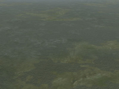
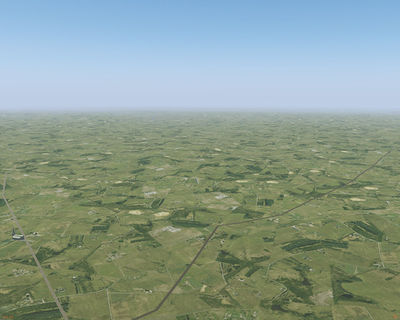
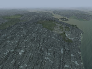
Procedural texturing is a solution to both the tiling and the resolution problem, and partially also for the boundary problem. A mathematical function, unlike a lookup table (which a texture in essence is) does not end at any boundary, i.e. it can simply be used across the whole scene without ever creating a repetition. Using a suitable noise function to mix various textures, a complete de-tiling effect can be achieved (this is really the same scene):
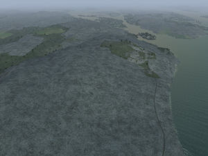
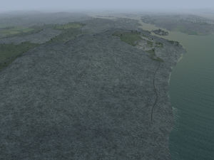
A function can also be evaluated at any scale resolution. Unlike a texture which needs to be stored regardless if it is used or not, a function only needs to be evaluated for every screen pixel, i.e. the workload and memory requirement do not grow quadratically with the needed resolution but only linear. This scaling allows to dynamically add details to the scene as one gets closer (this is really the same scene):
Building blocks of procedural texturing
Mathematical functions can describe quite complex structures, but in order to be rendered in real time, the function has to evaluate fast enough. This means that 'simple' textures like snow, or possibly sand or rock can be completely procedural, while more complex shapes like agriculture which shows fields, crops, access paths and drains can remain a texture with some structure added procedurally. In general, a mixture of textures and functions is used for best effect.
The most important building blocks of procedural texturing are noise functions. A noise function is a function which takes the coordinates of a pixel as input and returns a pseudo-random number between 0 and 1 as output. Noise functions aren't uniquely defined, and there are several possibilities:
Perlin noise
Perlin noise is noise which exists at a certain scale (say 10 m). It is built by dividing the scene into a 10m x 10 m grid, creating random values at each grid point and interpolating smoothly between the grid points. The function created that way varies typically at a scale of 10 m, but not at much smaller scales and averages to 0.5 at much larger scales. Perlin noise isn't so useful at just a single scale, but noise at several scales added together can achieve a very realistic effect of roughness and structure. Finding the correct noise frequencies and amplitudes for blending Perlin noise to a realistic appearance is an art rather than a computational task.
Sparse dot noise
For sparse dot noise, the terrain is divided into a grid at certain scale, then random values at the grid edges are used to determine if a dot is placed into the cell, where into the cell it is placed and what radius it has. Based on the distance to the dot, the function returns 0 if the point probed is far from the dot and 1 at the dot position.
From the superposition of several sparse dot distributions, dense dot distributions can be created. Note that a sparse dot distribution does not average to 0.5 but, dependent on the details of the implementation, to a much lower value.
Stratified noise
Stratified noise uses the terrain mesh altitude information to draw bands of constant altitude which each have a random number associated. The bands are then distorted in width by an altitude-dependent random number and modulated with an (xy)-position dependent random number. Stratified noise is rather useful for some types of rock formations.
Domain noise
The idea of domain noise is to segment the terrain into discrete patches, each of which has a random number associated. Unlike for Perlin noise, the number is not interpolated, it suddenly jumps at the domain boundary to a different value.
The FG implementation of domain noise uses a regular grid at some wavelength, then distorts the grid points by random numbers and uses Voronoi tiling to determine the domains within the distorted grid. This creates domains with a controllable irregularity which are all about the same size.
Domain noise is very useful for man-made patterns, e.g. managed forest, agriculture or cities.
Slope line noise
For slope line noise, the terrain is segmented in patches, and based on the normal of the terrain, a line along the direction of steepest descent is drawn on the patch, with precise line position and thickness modulated by random numbers. This type of noise mixed into Perlin noise can give a good impression of snow distributions on steep slope or erosion patterns on terrain.
Examples
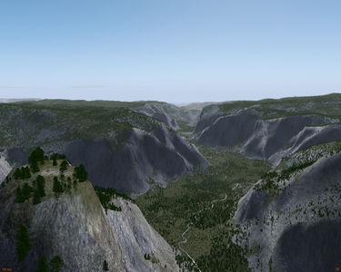
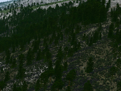
To the left is an example for domain noise scaling the size of trees in patches of few hundred meters size, thus giving the impression of the different age of forest patches in a managed forest. On the right is an example of slopeline noise, emphasizing the vertical structure of the granite walls in Yosemite National Park.
Terrain probing functions
The underlying terrain can also be used as input for functions in a different way. Commonly used functions are for instance the altitude of a terrain pixel (for instance to determine the snow line) or its slope (to place rock textures on steep slopes). Since the underlying vector geometry of the terrain mesh leads to very sharp division lines, usually terrain probing functions are mixed with some noise for a more realistic appearance.
Pixel color postprocessing
Many environmental effects can be simulated at the simple expense of post-processing the color of a terrain pixel. For instance, mixing every pixel with a constant dust color can give the terrain a dusty appearance, mixing the final pixel color with a mossy green can give it an overgrown appearance. This is similar to the way pixel color is adjusted for fog, but unlike fog effects environment pixel color postprocessing does not involve distance computations between eye and pixel, rather the color is adjusted independent of the distance (but possibly dependent on terrain gradient or altitude).
Procedural terrain texturing in Flightgear
As of Flightgear 2.10+, procedural texturing of the terrain is done by a general terrain shader which is configurable from materials.xml. The creation of separate effects for various terrain types is not required (but still possible if so desired).
Currently the following requires that Atmospheric light scattering is on!
Basic texturing scheme
The texturing scheme is controlled on a per-landclass basis from materials.xml. The relevant sections for procedural textruring in each material declaration are <texture-set> and <parameters>. Here the <texture-set> block controls what textures are used whereas the <parameters> block controls how these textures are used.
Another important part are <xsize> and <ysize> (the sections which describes to which size in meters the base texture is mapped). The procedural texturing shader computes the size of all used textures relative to the base texture size, so if a base texture is declared to have a size of 500 m rather than the default 2000 m, the resolution of the hires overlay or the grain texture will automatically also be 5 times higher then default - which may or may not be desired.
The individual textures which can be used are:
Base texture
The base texture is used as in the default scheme to give the basic appearance of a landclass. The base texture is assumed to be opaque, and its alpha channel is hence not evaluated to transparent, but rather used to encode where the autumn color effect should be used. An alpha value of 0.5 is appropriate for deciduous forests which should get a strong red-orange appearance in autumn, a value of 0.8-0.9 is more appropriate for grass surfaces.
The base texture can take some additional parameters. The first is intrinsic wetness. If the quality level of the shader supports it, this will make the texture appear wet and add sparkling specular reflections to the terrain even if the surrounding terrain is dry. The dust resistance acts in the opposite way, it is intended for irrigated terrain in desert areas and is a multiplier for the dust effect, i.e. a value of 0.0 will make a landclass completely impervious to dust. Finally, rock strata represents an integer flag whether a stratified pattern will be drawn on vertical surfaces or not.
- declaration:
<texture-set>
 <texture>base_texture.png</texture>
</texture-set>
- parameters:
<parameters>
 <intrinsic_wetness>0.0</intrinsic_wetness>
 <dust_resistance>1.0</dust_resistance>
 <rock_strata>0</rock_strata>
</parameters>
The default value of intrinsic wetness is zero, the parameter can range from 0 (dry) to 1 (very wet, lots of open water). The defaul value of duse resistance is one, and the parameter can range from 1 (gets dusty like everything else) to 0 (impervious to dust).
The overlay texture
The overlay texture is a texture at a similar resolution level which is mixed with the base texture to achieve de-tiling or gradient effects. By default, it covers about 50% of the available scene. As for the base texture, the alpha channel of the overlay texture encodes color rotations in autumn.
The overlay texture can be used in two different modes or a mixture of them. The control parameter is <transition_model> - if this parameter is set to 0, the transition between base and overlay texture is determined by a noise function. If the parameter is set to 1, the slope of the terrain determines the transition and the overlay texture is only used on steep slopes. A setting of 0.5 uses a mixture of noise and slope information to drive the transition.
- declaration:
<texture-set>
 <texture>base_texture.png</texture>
 <texture n="12">overlay_texture.png</texture>
</texture-set>
The default texture selected is void.png which corresponds to no overlay texture.
- parameters:
<parameters>
 <transition_model>0.5</transition_model>
</parameters>
The default value is 0.5, the parameter can range from 0 (random transition) to 1 (gradient-driven transition).
The hires texture
The hires texture adds patches of a texture at much higher resolution into the mix, which both add to de-tiling and lead to a better experience of the scenery from close-up. The hires textured patches will however inevitably appear featureless from large distance and will show tiling themselves, so the amount of hires texture as well as the hires texture sheet itself must be designed carefully.
The areas covered by the hires texture will (partially to mask tiling of the hires patches) receive a stronger bumpmap and some distortion than the rest of the terrain by the shader.
As for the base texture, the alpha channel of the hires texture encodes color rotations in autumn.
The parameter <hires_overlay_bias> controls the fraction of terrain covered by the hires texture patches - by default about 40% of the scene will be covered. Positive or negative biases can make the fraction arbitrarily small or large.
- declaration:
<texture-set>
 <texture>base_texture.png</texture>
 <texture n="11">hires_texture.png</texture>
 <texture n="12">overlay_texture.png</texture>
</texture-set>
The default texture selected is void.png which corresponds to no hires texture. The hires texture does not require the overlay texture to be declared.
- parameters:
<parameters>
 <hires_overlay_bias>0.0</hires_overlay_bias>
</parameters>
The default value is 0.0, the parameter can range from -0.5 (strong suppression of the hires overlay texture) to +0.5 (strong enhancement of the hires overlay texture).
The gradient texture
The gradient texture is exclusively used for steep terrain gradients (significantly steeper than the point at which the overlay texture may be used) to account for the fact that beyond a certain slope, terrain can not have vegetation cover and hence landclass information needs to be corrected if necessary.
The default texture is rock.png which is hence used for all landclasses unless specifically declared otherwise. The default may be inappropriate in some regions (volcanic terrain with different rock hue, tropical terrain in which even steep slopes are covered) - the gradient texture then needs to be declared a different texture for all materials in the area. Declaring void.png will not use a gradient texture.
The gradient texture does not use any parameters.
- declaration:
<texture-set>
 <texture>base_texture.png</texture>
 <texture n="11">hires_texture.png</texture>
 <texture n="12">overlay_texture.png</texture>
 <texture n="13">gradient_texture.png</texture>
</texture-set>
The grain texture
The grain texture adds a grainy pattern to the terrain at close distances, giving the appearance of better resolution. The grain texture parses the texture alpha channel as transparency (since it just superimposes a pattern), so here the alpha channel can not be used to encode vegetation effects, and the grain texture may not have a strong color.
To allow fine-tuning of the grain effect, the texture can be multiplied with the <grain_strength> parameter which sets the overall alpha of the grain effect - a low value works best on bright base textures whereas dark base textures may require a stronger grain.
The default grain texture is grain_texture.png which adds a vegetation-like grain. This can be replaced with other grain patterns or void.png for no grain where appropriate.
- declaration:
<texture-set>
 <texture>base_texture.png</texture>
 <texture n="11">hires_texture.png</texture>
 <texture n="12">overlay_texture.png</texture>
 <texture n="13">gradient_texture.png</texture>
 <texture n="14">grain_texture.png</texture>
</texture-set>
- parameters:
<parameters>
 <grain_strength> 0.5</grain_strength>
</parameters>
The default value is 0.5 and the parameter range is 0 (completely transparent) to 1 (completely opaque).
The dot texture
The dot overlay uses sparse dot noise to create detail in the scene. Sparse dot noise textured with a rock texture can give the appearance of boulders scattered across the terrain, the same noise textured with a grass texture can be used to create round vegetation patches.
Both the dot size and the dot density can be controlled by the user. The range out to which the dots are visible is automatically adjusted based on the dot size scale. By default, the dot texture is set to void.png, which means that no dot texture is used.
- declaration:
<texture-set>
 <texture>base_texture.png</texture>
 <texture n="11">hires_texture.png</texture>
 <texture n="12">overlay_texture.png</texture>
 <texture n="13">gradient_texture.png</texture>
 <texture n="14">grain_texture.png</texture>
 <texture n="15">dot_texture.png</texture>
</texture-set>
- parameters:
<parameters>
 <dot_density> 1.0</dot_density>
 <dot_size> 1.0</dot_size>
</parameters>
The default value for <dot_density> is 1.0, the parameter can be set in the range from 0.0 to 1.0 (values above 1.0 do not increase the dot density further). The default value for <dot_size> is also 1.0, which creates dots at size scales varying between 10 cm and few m. The parameter is a multiplier for these default values, i.e. at a value of 10 dots of ~10-20 m size are created.
Examples
The following declaration
 <texture-set>
  <texture>Terrain/marsh2.png</texture>
  <texture n="11">Terrain/grass_hires.png</texture>
  <texture n="12">Terrain/marsh4a.png</texture>
  <texture n="15">Terrain/airport_grass2.png</texture>
 </texture-set>
 <parameters>
  <grain_strength>0.9</grain_strength>
  <intrinsic_wetness>0.6</intrinsic_wetness>
 </parameters>
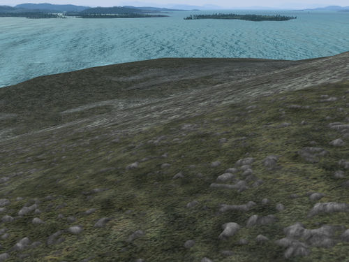
results in marshland drawn like this
The following declaration
  <texture-set>
   <texture>Terrain/shrub-hawaii.png</texture>
   <texture n="11">Terrain/sand_hires_red.png</texture>
   <texture n="12">Terrain/rock_red.png</texture>
   <texture n="13">Terrain/rock_red.png</texture>
   <texture n="14">Terrain/grain_texture.png</texture>
   <texture n="15">Terrain/airport_grass2.png</texture>
  </texture-set>
  <parameters>
   <rock_strata>1</rock_strata>
  </parameters>
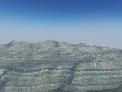
results in stratified rock structures like the following:
The agriculture effect
The basic texture scheme based on Perlin noise is of limited value for e.g. agricultural terrain which rarely shows the organic shapes generated by Perlin noise. For such terrain, the agriculture effect should be used instead which is based on Perlin noise.
The effect needs to be declared for the landclass as
<effect>Effects/agriculture</effect>
(note that since the default rendering scheme has typically the crop effect associated with agriculture, this declaration inherits crop.eff).
By default, large patches of agriculture usually show strong tiling:
It is implemented in two modes, overlay and rotation. Since the agriculture effect is optional, its overlay texture is declared separately from the normal declaration above as follows:
  <texture-set>
   <texture>base_texture.png</texture>
   <texture n="16">overlay_texture.png</texture>
  <texture-set>
If the overlay texture is declared void.png (to which the effect defaults), it is not used. The effect takes a number of parameters. For the overlay, the fraction taken by the overlay texture and the scale at which the patches are drawn can be specified through the overlay fraction and the overlay scale, while the shape of the domains can be controlled using a distortion factor.
  <overlay_fraction>0.5</overlay_fraction>
  <overlay_scale>1000.0</overlay_scale>
  <distortion_factor>0.3</distortion_factor>
This results in the overlay texture superimposed in irregular patches.
De-tiling can also be achieved by rotating the texture coordinates inside patches. This is controlled by a rotation flag which can be set to 1 (random rotation) or 2 (rotation by multiples of 90 degrees only) in addition to a rotation scale. In case of very regular textures which should be rotated by multiples of 90 degrees only, uv texture coordinate offsets are provided to align texture and rotated domain.
  <rotation_flag>1</rotation_flag>
  <rotation_scale>2000.0</rotation_scale>
  <uv_xoffset>0.0</uv_xoffset>
  <uv_yoffset>0.0</uv_yoffset>
Using domain rotation also leads to a reasonable de-tiling while keeping the color impression.
Both rotation and overlay can be combined. Neither of the effects is compatible with patterns of random trees of buildings created by placement masks, as these are used at tile loading time and can not be changed runtime like shader effects.
The rock effect
Specifically for rock, a completely procedural scheme to generate various types of rock structures is available. Since this is computationally about on par with the overlay texture schemes for generic terrain, it activates only at highest rendering quality level.
The effect needs to be declared for the landclass as
<effect>Effects/rock</effect>
Rock is drawn by overlaying several structure layers. The base layer is set by several octaves of Perlin noise superimposed as brightness variation onto a specified texture color. The relevant configuration parameters are e.g.
  <base-color type="vec3d">0.9 0.95 0.94</base-color>
  <contrast type="float">0.7</contrast>
  <grain-fade-power type="float">1.3</grain-fade-power>
  <rock-brightness type="float">1.0</rock-brightness>
Here, <base-color> is a rgb triplet with color values ranging from 0 to 1 specifying the primary hue of the rock to be drawn. <ontrast> regulates how strongly the noise modification of rock brightness will appear from 0 (no noise modulation) to 1 (full noise modulation). <grain-fade-power> regulates the balance between large-scale and small-scale noise. Values above 1 will emphasize small-scale structures, values below 1 will emphasize large-scale structures. There is no real limit to the parameter, but presumably values outside [0.5:1.5] won't look compelling.
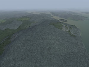
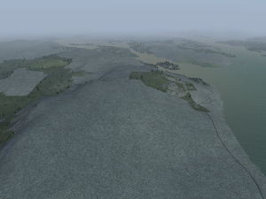
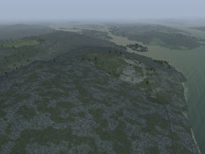
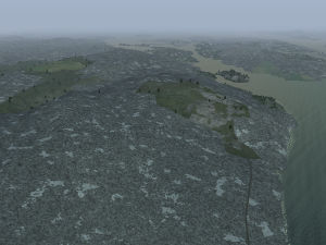
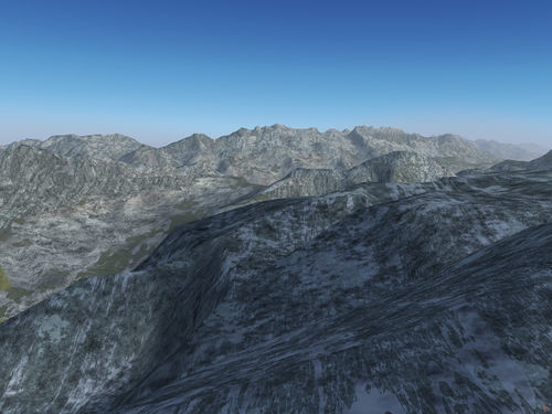
The effect of the fade power ranging from 0.8 to 1.3 is illustrated by the following series of screenshots:
The effect of the contrast parameter changing from 1.0 to 0.7 looks as follows:
Since it is difficult to guess the resulting visual brightness of rock after all noise and overlay patterns have been added, <rock-brightness> is a convenient scale after to multiply pixel color after all layers have been added.
The overlay layer is based on Perlin noise domains and draws with a different color onto the base layer. The relevant parameters are
  <overlay-color type="vec3d">0.9 0.95 0.94</overlay-color>
  <overlay-alpha type="float">0.8</overlay-alpha>
  <overlay-bias type="float">-0.05</overlay-bias>
Here, the <overlay-color> is again a rgb triplet and <overlay-alpha> its transparency value. <overlay-bias> should take values between -0.5 and 0.5 and controls the amount of surface to be covered with the overlay color.
As illustrated by the following screenshots, the overlay layer can be used to draw moss and lichen cover as well as mineral crusts on top of the base rock layer:
The crack layer is based on stretched Perlin noise isolines and controlled by the parameters
  <crack-depth type="float">0.9</crack-depth>
  <crack-pattern-stretch type="float">1.0</crack-pattern-stretch>
The <crack-depth> (from 0 to 1) regulates how pronounced the darkening inside the crack region is whereas the <crack-pattern-stretch> (from 1 to roughly 10) controls the elongation of the crack pattern.
For low stretch values, the crack layer can be used to draw bands of different mineral inside the rock, for high stretch values it can simukate a genuine pattern of cracks in the surface, see screenshots below for an illustration:
Finally, stratified and slope line noise (see above) are also available as texture brightness modifiers. The parameters are
  <slope-contrast type="float">0.5</slope-contrast>
  <rock_strata type="int">0</rock_strata>
<slope-contrast> (value between 0 and 1) regulates how pronounced the slope lines are drawn and <rock_strata> (value 0 or 1) indicated whether stratified noise should be used or not. Neither slope noise nor stratified noise affect flat rock surfaces, they only lead to modulation on sufficiently steep rock surfaces.
Example 1:
This parameter set
  <base-color type="vec3d">0.9 0.95 0.94</base-color>
  <overlay-color type="vec3d">0.9 0.95 0.94</overlay-color>
  <overlay-alpha type="float">0.4</overlay-alpha>
  <overlay-bias type="float">0.0</overlay-bias>
  <contrast type="float">1.0</contrast>
  <slope-contrast type="float">0.3</slope-contrast>
  <crack-depth type="float">0.6</crack-depth>
  <crack-pattern-stretch type="float">7.0</crack-pattern-stretch>
  <rock-brightness type="float">1.0</rock-brightness>
  <grain-fade-power type="float">1.0</grain-fade-power>
  <rock_strata>0</rock_strata>
results in rock drawn like this:
Example 2:
The following set of parameters
  <base-color type="vec3d">0.9 0.95 0.94</base-color>
  <overlay-color type="vec3d">0.9 0.95 0.94</overlay-color>
  <overlay-alpha type="float">0.4</overlay-alpha>
  <overlay-bias type="float">0.0</overlay-bias>
  <contrast type="float">0.8</contrast>
  <slope-contrast type="float">0.2</slope-contrast>
  <crack-depth type="float">0.5</crack-depth>
  <crack-pattern-stretch type="float">1.0</crack-pattern-stretch>
  <rock-brightness type="float">1.3</rock-brightness>
  <grain-fade-power type="float">0.8</grain-fade-power>
  <rock_strata>1</rock_strata>
leads to stratified rock like this:
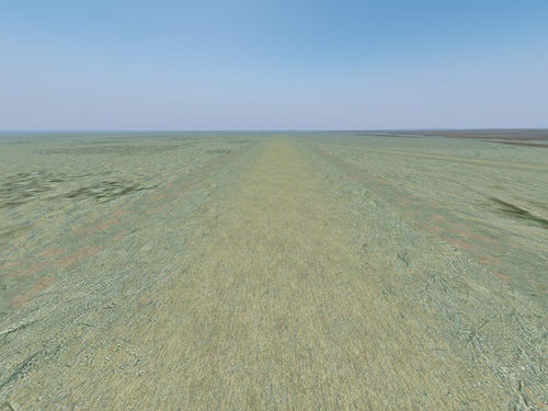
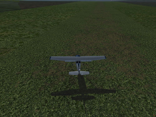
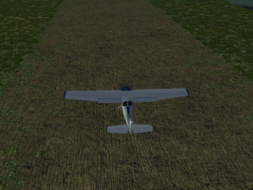
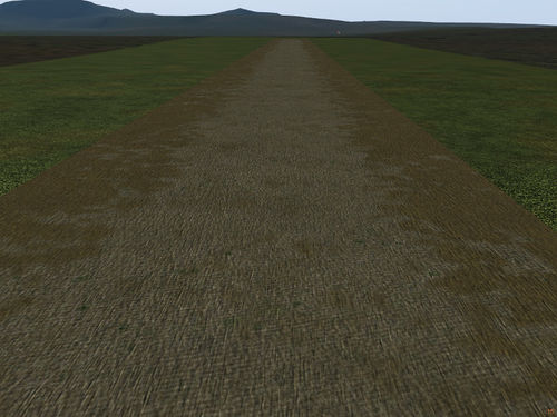
The dirt runway effect
Using a dedicated ALS effect, it is possible to generate a wide variety of visuals for non-paved runways. The effect is used to texture a runway as
<effect>Effects/dirt-runway</effect>
and the textures and parameters to configure it must be specified in the <parameters> section of the landclass used for the runway.
Important note: Part of the effect explicitly relies on a particular uv-mapping of the dirt runways. For this reason, the effect may or may not work as intended with scenery other than FG world scenery 2.0 - in particular custom scenery builds may not give the desired visuals if they treat unpaved runways differently.
The effect uses a mixture of three texture layers - a base texture layer (n=16) an overlay texture layer (n=17) and a grain texture layer (supposed to be a largely transparent texture with just a darker overlay pattern on it, n=18).
For each of the textures, a mapping to a physical size of the texture patch can be defined by the set of parameters
      <size_base>25.0</size_base>
      <size_overlay>100.0</size_overlay>
      <size_grain>100.0</size_grain>
(i.e. setting a parameter to 100 means that the texture sheet is supposed to represent a 100 m x 100 m patch of runway). This is different from the way the default renderer treats dirt runways by stretching the assigned texture over the whole runway (i.e. texture magnification depends on runway size). The strength of the grain overlay can be controlled by
<grain_strength>0.3</grain_strength>
where a value of zero implies no grain texture and a value of 1 the full grain effect as on the texture.
The mixture of base and overlay texture layers is controlled by filtered Perlin noise. The frequencies of the base noise distribution can be controlled by
      <strength_05m>0.0</strength_05m>
      <strength_1m>0.4</strength_1m>
      <strength_2m>0.3</strength_2m>
      <strength_5m>0.2</strength_5m>
      <strength_10m>0.1</strength_10m>
where the sum of all parameters is supposed to be 1. Strengthening a parameter generates more structure at this scale, for instance in order to generate a small-scale, fine-grained pattern one should set the lower frequencies to larger values, whereas for large continuous patches of texture strength_10m and strength_5m should be largest.
The raw Perlin noise is post-processed by a filter driven by two parameters.
      <filter_threshold>0.2</filter_threshold>
      <filter_transition>0.2</filter_transition>
Of these, the threshold regulates the relative mixture of the two textures (0.5 roughly corresponds to 50%) and transition how the mixture will be drawn. A small transition value (say 0.1) corresponds to an either/ or scenario in which only one of the textures will be drawn (appropriate for grass patches on dirt), a large transition value smoothly blends the textures (appropriate for different sand textures).
If
<bias_center>1</bias_center>
is set to 1, the noise distribution will tend to favor the base layer in the center of the runway. This requires a specific uv-mapping and will not work for custom-generated runways. The strength of that bias is set by
<bias_center_strength>0.6</bias_center_strength>
which is between 0 (no bias) and 1 (don't draw overlay layer in runway center no matter what).
In addition, the effect uses a normal map (since it is used in a non-standard way, touch at your own risk) - the visual 'bumpiness' of the runway can be adjusted using
<relief_strength>0.35</relief_strength>
Using different mixtures of textures and parameters, a wide variety of visuals can be achieved, a few examples in the following.
A lakebed texture overlaid with sand gives proper visuals for e.g. the Rogers Dry Lake runways at Edwards AFB:
    <texture-set>
      <texture>Runway/lakebed_taxiway.png</texture>
      <texture n="16">Terrain/sand_hires.png</texture>
      <texture n="17">Terrain/sand1.png</texture>
    </texture-set>
    <parameters>
      <strength_05m>0.0</strength_05m>
      <strength_1m>0.4</strength_1m>
      <strength_2m>0.3</strength_2m>
      <strength_5m>0.2</strength_5m>
      <strength_10m>0.1</strength_10m>
      <filter_threshold>0.2</filter_threshold>
      <filter_transition>0.2</filter_transition>
      <bias_center>1</bias_center>
      <bias_center_strength>0.6</bias_center_strength>
      <relief_strength>0.35</relief_strength>
      <size_base>25.0</size_base>
      <size_overlay>100.0</size_overlay>
      <size_grain>100.0</size_grain>
      <grain_strength>0.3</grain_strength>
    </parameters>
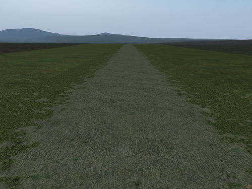
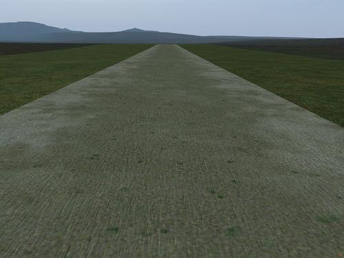
Using a largely grass-textured surface and allowing some gravel to show in the runway center gives the appearance of a worn grass runway:
   <texture-set>
      <texture>Runway/dirt_rwy.png</texture>
      <texture n="16">Terrain/sand_hires_ochre.png</texture>
      <texture n="17">Terrain/airport_grass2.png</texture>
    </texture-set>
    <parameters>
      <strength_05m>0.3</strength_05m>
      <strength_1m>0.4</strength_1m>
      <strength_2m>0.0</strength_2m>
      <strength_5m>0.1</strength_5m>
      <strength_10m>0.2</strength_10m>
      <filter_threshold>0.15</filter_threshold>
      <filter_transition>0.1</filter_transition>
      <bias_center>1</bias_center>
      <bias_center_strength>0.6</bias_center_strength>
      <relief_strength>0.35</relief_strength>
      <size_base>25.0</size_base>
      <size_overlay>30.0</size_overlay>
      <size_grain>50.0</size_grain>
      <grain_strength>0.8</grain_strength>
    </parameters>
Using the effect 'as is', i.e. without any additional parameters, reproduces the old appearance of the dirt runway effect in ALS:
With the original dirt runway texture mapped to a small size and framed by less structured dirt, also a compelling result can be achieved:
    <texture-set>
      <texture>Runway/dirt_rwy.png</texture>
      <texture n="16">Runway/dirt_rwy.png</texture>
      <texture n="17">Terrain/sand_hires_ochre.png</texture>
    </texture-set>
    <parameters>
      <strength_05m>0.0</strength_05m>
      <strength_1m>0.4</strength_1m>
      <strength_2m>0.3</strength_2m>
      <strength_5m>0.2</strength_5m>
      <strength_10m>0.1</strength_10m>
      <filter_threshold>0.2</filter_threshold>
      <filter_transition>0.2</filter_transition>
      <bias_center>1</bias_center>
      <bias_center_strength>0.6</bias_center_strength>
      <relief_strength>0.35</relief_strength>
      <size_base>25.0</size_base>
      <size_overlay>25.0</size_overlay>
      <size_grain>25.0</size_grain>
      <grain_strength>0.4</grain_strength>
    </parameters>
Using grass as the overlay material blends the runway outline nicely into the airport keep:
    <texture-set>
      <texture>Runway/dirt_rwy.png</texture>
      <texture n="16">Runway/lakebed_taxiway.png</texture>
      <texture n="17">Terrain/airport_grass2.png</texture>
    </texture-set>
    <parameters>
      <strength_05m>0.2</strength_05m>
      <strength_1m>0.6</strength_1m>
      <strength_2m>0.2</strength_2m>
      <strength_5m>0.0</strength_5m>
      <strength_10m>0.0</strength_10m>
      <filter_threshold>0.2</filter_threshold>
      <filter_transition>0.1</filter_transition>
      <bias_center>1</bias_center>
      <bias_center_strength>0.8</bias_center_strength>
      <relief_strength>0.35</relief_strength>
      <size_base>25.0</size_base>
      <size_overlay>25.0</size_overlay>
      <size_grain>20.0</size_grain>
       <grain_strength>0.6</grain_strength>
    </parameters>
Finally an example of diffuse sand patches blended into each other by low frequency noise and a large value of the transition in the filter:
    <texture-set>
      <texture>Runway/dirt_rwy.png</texture>
      <texture n="16">Runway/lakebed_taxiway.png</texture>
      <texture n="17">Terrain/sand_hires.png</texture>
    </texture-set>
    <parameters>
      <strength_05m>0.0</strength_05m>
      <strength_1m>0.2</strength_1m>
      <strength_2m>0.3</strength_2m>
      <strength_5m>0.3</strength_5m>
      <strength_10m>0.2</strength_10m>
      <filter_threshold>0.2</filter_threshold>
      <filter_transition>0.4</filter_transition>
      <bias_center>1</bias_center>
      <bias_center_strength>0.5</bias_center_strength>
      <relief_strength>0.35</relief_strength>
      <size_base>25.0</size_base>
      <size_overlay>25.0</size_overlay>
      <size_grain>20.0</size_grain>
      <grain_strength>0.2</grain_strength>
    </parameters>
Overlay layers
The ALS rendering framework also supports rendering a low layer with a '3D' structure which is created dynamically by a geometry shader - this can be used for undergrowth or rocks - see below for an example of undergrowth in northern boreal forest:
The overlay layer is created by extruding a number of 'shells' from the base ground surface (with a LOD system controlling how many shells are extruded) and texturing the part of the shell which intersects with the 3d structure of the object to be rendered. This looks fairly compelling from above, but of course for shallow viewing angles the nature of the illusion is readily apparent, and once the view direction is parallel to the shells, the 3D structure vanishes because one is looking right between shells. It's therefore a good idea to keep the overlay layer low (< 1 m) and supplement it with other elements such as random vegetation.
The overlay layer needs to be both enabled in user preferences and requested by the landclass definition to be shown. In the materials file, the corresponding effect needs to be set as
<effect>Effects/terrain-overlay</effect>
to enable the layer. If the overlay is not selected in the ALS quality levels, the effect will automatically fall back to terrain-default (the same will happen if ALS is not selected as renderer).
In the materials file, a number of parameters govern the appearance of the overlay layer. The following example is from Hawaii texturing (here (...) means that these declarations for the layer need to be done in addition to other procedural texturing described above).
        <texture-set>
          (...)
	  <texture n="20">Terrain/dry_pasture4.png</texture>
	  <texture n="21">Terrain/dry_pasture4.png</texture>
	</texture-set>
	<parameters>
          (...)
	  <max_overlay_height>1.0</max_overlay_height>
	  <overlay_hardness>0.0</overlay_hardness>
	  <overlay_density>0.6</overlay_density>
	  <overlay_scale>2.0</overlay_scale>
	  <overlay_autumn_flag>0</overlay_autumn_flag>
	  <overlay_brightness_top>0.8</overlay_brightness_top>
	  <overlay_brightness_bottom>0.4</overlay_brightness_bottom>
	  <overlay_secondary_flag>1</overlay_secondary_flag>
	  <overlay_secondary_hardness>0.0</overlay_secondary_hardness>
	  <overlay_secondary_density>1.0</overlay_secondary_density>
         </parameters>
Let's go through these entries.
First, the overlay layer can support two different structures with different textures (for instance undergrowth and rock). The number 20 defines the texture for the primary layer, the number 21 for the secondary layer. The code makes an assumption that the secondary layer is smaller in height than the primary layer, so plan accordingly.
The first four parameters determine the apparent geometry of the overlay objects. All 'objects' (which really are painted on the shells only, remember) are based on Perlin noise to give them a pseudo-random appearance. <max_overlay_height> is the maximal distance the upper layer will be extruded from the ground - the largest of the random structures will reach to this level. As mentioned above, it's generally a good idea to keep this < 1 m (although the effect will run for higher numbers). The <overlay_hardness> is a number between 0 and 1 and determines how blurry the edges of the structures will be - generally for vegetation one wants a low hardness, for rock (see below) a high hardness to get the illusion of a well-defined surface).
The <overlay_density> determines how much overlay objects there will be (technically, it's a bias for the Perlin noise) - a high density will give a nearly closed layer, a low density instead only a few objects far and between. Finally, the <overlay_scale> is a parameter used to stretch the noise pattern horizontally. By default, the pattern is around 1-2 m scale, setting the parameter e.g. to 5 will stretch this horizontally to 5-10 m (while leaving the vertical height constant).
The overlay layer is fully interfaced with pixel-post-processing (see below). It is automatically submerged in snow based on altitude information and the simulated snow level, but the shader can not know whether a structure is supposed to be rock or vegetation, thus to participate in autumn coloring, the <overlay_autumn_flag> needs to be set.
A nice shading effect bringing out the 3d structure better (a cheap version of ambient occlusion basically) can be achieved by setting <overlay_brightness_top> and <overlay_brightness_bottom> to different values (these are multiplies for the base texture color). What the best values should be really depends on the texture that is used.
The secondary layer shares most properties with the primary layer. It needs to be activated using <overlay_secondary_flag> and it is possible to give it a different apparent hardness and density using <overlay_secondary_hardness> and <overlay_secondary_density>. Since the secondary layer utilizes the same Perlin noise generated for the primary layer, the two layers can not generate overlapping structures by constructions (thus, no 'bush' and merge with a 'rock'). That also means that a secondary layer with texture and parameters identical to the primary layer can be declared to generate an extra-dense layer. Generally though secondary layers should be used with care.
Pixel color postprocessing
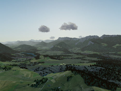
A number of environment effects are implemented under user control in the Environment menu. Let's consider the changes to the base scene:
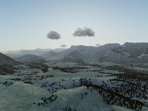
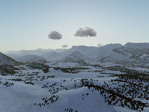
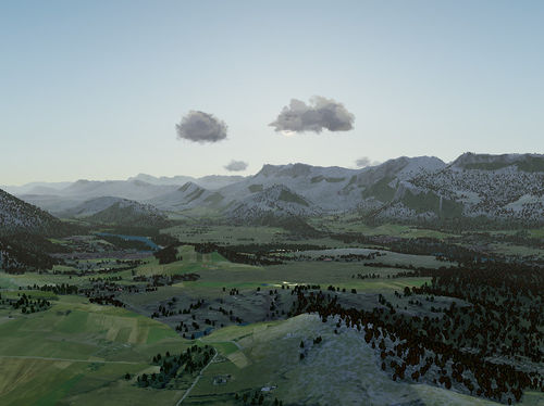
Snow
Using terrain elevation and gradient information, the base location of a snow layer can be determined. The actual snow cover is a white base color, mixed with Perlin noise and normal-mapped with Perlin noise of multiple frequencies. A bias factor for the mixing allows to simulate snow layer of varying thickness.
A low layer thickness creates patches of snow on the terrain through which the basic terrain textures are visible:
A high layer thickness completely covers the terrain in snow. Subtle procedural color variations of the snow and bump-mapping change the base white snow pixel color into a realistic texture:
If the snowline is placed higher, snow is only simulated on the mountain tops - note also that steep gradients tend to remain clear of snow:
Dust
The dust effect mixes all pixels of the terrain with a basic dust color. A low dust effect setting gives the terrain a dry and parched appearance, as after a long summer period without rain.
A high dust effect setting changes the appearance to desert-like terrain (which is rather unrealistic for this scenery):
Wetness
Wet terrain is rendered overall darker. In flat areas, in addition patches of high specular reflection are added, leading to the appearance of glitterin light reflections on water puddles.
Vegetation
A high setting of the vegetation cover is most appropriate for tropical settings, but it can also be used to show seasonal effects, for instance the desert a few days after rainfall. It covers the whole terrain with mossy overgrowth, which in the case of the Grenoble scenery used here blurs the boundaries of the fields and gives the appearance of abandoned agriculture.
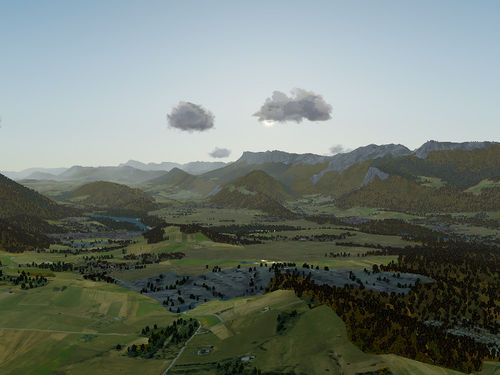
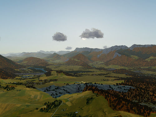
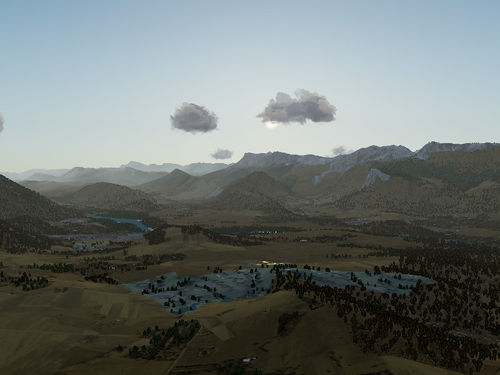
Autumn colors
The autumn color effect is unique in the pixel color postprocessing effects in that it needs modifications to the base texture to work. Since the basic terrain texture is never transparent, the information of where vegetation changes color in autumn and where it remains unchanged is hence encoded in the terrain texture alpha channel. A value of 1 means no change of color, a value of 0.5 is appropriate for high changes to bright red-orange. In order to work with the autumn effect, all textures need to be edited manually to indicate where the effect should be computed.
In early autumn, vegetation just tends to pale a little:
Later, fields get bright golden-yellow whereas deciduous forests go to orange-red (mixed forest cover rotates locally where indicated by the alpha channel):
Finally, in late autumn all vegetation cover is turned into a dull brown:
Limitations of procedural texturing
Despite its obvious benefits, there are some problems which are not easily addressed by procedural terrain texturing.
- Landclass boundaries: Procedural texturing can de-emphasize landclass boundaries. This happens for instance if a landclass uses both overlay and detail texture, and only the base texture is changed in the adjacent landclass. Since the noise is continuous across landclass boundaries, the change in base texture is masked by the continuous overlay components. However, procedural texturing can not remove the landclass seams, as a different texture mix is evaluated for every declared landclass.
- Detail averaging: A problem arises when details are generated which are smaller than a pixel. In this case, the rendering engine does not average over many sub-pixels to determine the final color of the pixel but just takes one (few) samples. This means that a high contrast detailed structure of black and white is not averaged to a grey pixel but, dependent on the viewer position, either results in a black or a white pixel. The net result is a flickering Moire pattern which is visually very unpleasant (the same effect occurs when models get smaller than a pixel). In textures, the problem is solved by mipmapping - every 4 pixels are averaged to a single pixel on a coarse-grained version of the texture at texture loading time, and only the appropriate resolution level of the texture is referenced. To do the same thing in procedural texturing is very expensive (two resolution levels up one ends with 16 times the calculational effort for a pixel), so a viable strategy to remove the flickering patterns involves replacing noise by its global average (i.e. the 'all pixel' rather than '4 pixel' average, which is usually known for the noise function). The net result is that procedurally generated details tend to looks less grainy than true textures as soon as details get smaller than a single pixel, which is s subtle, but noticeable effect. In essence, this is similar to an antialiasing problem and could also be dealt with by generically sampling multiple sub-pixels at the expense of the increased performance cost.
- Computational cost: Especially on older graphics cards, multiple texture lookups combined with evaluating noise and other functions is significantly slower than just texturing the terrain with a single texture. Most optimization strategies used in other 3D games (such as filling the z-buffer early and discarding occluded pixels) do not work well for a flight simulator where most of the terrain is visible at any given time.
Some points have found a solution:
- Terrain tile boundaries: Terrain is loaded in discrete chunks, so-called tiles. For technical reasons, the coordinate system used to address positions changes for each tile. In practice, this unfortunately implies that noise functions are discontinuous across tile boundaries, and this shows in more or less pronounced seams in the computed textures -> however this can be addressed by going from tile-based to FG world coordinates and using 3-d noise. Due to the large distances involved, small-scale noise becomes then numerically unstable, but noise wavelength above 250 m can safely be done in world coordinates, leading to appealing visuals both at large and small distance.
- Tiling for non-natural landclasses: The de-tiling strategies described above are based on mixing texture components using noise functions. This works fine for natural landclasses, but human-influenced landclasses like agriculture or urban terrain are not well described by Perlin noise, and de-tiling crop fields using noise functions does not yield plausible results.This is now solved by domain noise.
Related content
Wiki articles
Forum topics
- Finding textures from Open Aerial Map, extracting with QGIS topic on the forum
 - Has posts describing the advantages of features on several scales compared to pure orthophoto materials.
Further reading
- From random number to texture - GLSL noise functions
- http://www.upvector.com/?section=Tutorials&subsection=Intro%20to%20Procedural%20Textures
- http://www.graphics.usc.edu/cgit/publications/papers/p95-rhoades.pdf
- http://www.vis.uni-stuttgart.de/~dachsbcn/download/ProcReproduction.pdf
- http://www.unilim.fr/pages_perso/guillaume.gilet/Recherche/pdf/CGI12.pdf
- http://www.mail-archive.com/flightgear-devel@lists.sourceforge.net/msg39692.html
