Howto:Modelling hydrodynamics in JSBSim
Introduction
This page intends to describe how to model hydrodynamic forces and moments in JSBSim (i.e. how things interact with water). It is based around JSBSim external forces and a couple of generic systems for JSBSim that are available in FGData, namely hydrodynamics.xml, hydrodynamic-planing.xml and hydrodynamic-planing-floats.xml.
NOTE: These methods and systems are under active, but slow development, there are known and unknown bugs and inconsistencies present. Future developments may require changes in the per-aircraft files.
The hydrodynamics.xml system receives forces and moments due to the vessel's interaction with water, both hydrostatic and hydrodynamic, defined with respect to the hydrodynamic reference point (HRP) in a separate per-aircraft file and apply them to the vessel using external forces.
The coordinate frame used to define the forces and moments is similar to the body frame but is always aligned with the water surface which is assumed to be horizontal. Forces can also be defined in a horizontal "wind" frame.
NOTE: This is one point where there are known inconsistencies present (read: the coordinate frame definitions need to be sorted out). However, as long as pitch and heel angles are small this should not lead to major issues.
The forces are split into the channels
- Fbx - body forward. (In the water plane?)
- Fby - body right. (In the water plane?)
- Fbz - local up (the same as -Z in the JSBSim local frame).
- Drag - opposing the relative water flow. (In the water plane?)
- Side - 90 degrees right from the relative water flow in the surface plane.
The moments are split into the hydrodynamic body frame channels (with the same sense as the normal body frame moments):
- Pitch (angle: positive is nose up)
- Yaw
- Roll (angle and moment: positive is left wing up)
The properties determining the location and orientation of the vessel w.r.t the the water surface and stream are:
- hydro/height-agl-ft - Height of the hydrodynamic reference point over the water surface.
- hydro/beta-deg - angle between the vessel's velocity vector through the water and its longitudinal axis. Analogous to aerodynamics/beta-deg.
- hydro/pitch-deg - angle between the vessel longitudinal axis and the water surface (ground plane).
- hydro/roll-deg - angle between the vessel transverse axis and the water surface (ground plane).
- hydro/v-fps - The vessel's total speed relative the water.
Basic usage
Include the hydrodynamics.xml system in your vessel/aircraft.
Define the following properties in a system of your aircraft:
- Hydrodynamics reference point in the structural frame:
    <property value="...">metrics/hydro-rp-x-in</property>
    <property value="...">metrics/hydro-rp-y-in</property>
    <property value="...">metrics/hydro-rp-z-in</property>
- Reference dimensions (used for the experimental wave interactions, but may also be used as reference dimensions for hydrodynamic coefficients in the aircraft specific system):
    <property value="...">metrics/hydro-beam-ft</property>
    <property value="...">metrics/hydro-length-ft</property>
    <property value="...">hydro/hull-length-ft</property> <!-- Deprecated. Not used by hydrodynamics.xml from FlightGear 2017.2.1. -->
- Functions computing the forces in the hydrodynamic body frame
   - hydro/fbx-lbs
   - hydro/fby-lbs
   - hydro/fbz-lbs
Alternative force inputs in the water frame
   - hydro/fdrag-lbs
   - hydro/fside-lbs
Unused properties also have to be declared (and set to zero).
- Functions computing the moments in the hydrodynamic body frame. FIXME: Yaw is applied in the standard body frame.
   - hydro/yaw-moment-lbsft
   - hydro/pitch-moment-lbsft
   - hydro/roll-moment-lbsft
Define the following external forces in the main FDM file of your aircraft, they will be used to apply the hydrodynamic forces and moments to the vessel:
    <force name="hydro-X" frame="LOCAL">
     <location unit="M">
      { HRP }
     </location>
     <direction>
      <x> 1.0 </x>
      <y> 0.0 </y>
      <z> 0.0 </z>
     </direction>
    </force>
    <force name="hydro-Y" frame="LOCAL">
     <location unit="M">
      { HRP }
     </location>
     <direction>
      <x> 0.0 </x>
      <y> 1.0 </y>
      <z> 0.0 </z>
     </direction>
    </force>
    <force name="hydro-Z" frame="LOCAL">
     <location unit="M">
      { HRP }
     </location>
     <direction>
      <x> 0.0 </x>
      <y> 0.0 </y>
      <z>-1.0 </z>
     </direction>
    </force>

    <force name="hydro-pitch[0]" frame="LOCAL">
     <location unit="M">
      <x> HRP X - 0.3048 </x>
      <y> HRP Y </y>
      <z> HRP Z </z>
     </location>
     <direction>
      <x> 0.0 </x>
      <y> 0.0 </y>
      <z>-1.0 </z>
     </direction>
    </force>
    <force name="hydro-pitch[1]" frame="LOCAL">
     <location unit="M">
      <x> HRP X + 0.3048 </x>
      <y> HRP Y </y>
      <z> HRP Z </z>
     </location>
     <direction>
      <x> 0.0 </x>
      <y> 0.0 </y>
      <z>-1.0 </z>
     </direction>
    </force>

    <force name="hydro-yaw[0]" frame="BODY">
     <location unit="M">
      <x> HRP X </x>
      <y> HRP Y - 0.3048 </y>
      <z> HRP Z </z>
     </location>
     <direction>
      <x> 1.0 </x>
      <y> 0.0 </y>
      <z> 0.0 </z>
     </direction>
    </force>
    <force name="hydro-yaw[1]" frame="BODY">
     <location unit="M">
      <x> HRP X </x>
      <y> HRP Y + 0.3048 </y>
      <z> HRP Z </z>
     </location>
     <direction>
      <x> 1.0 </x>
      <y> 0.0 </y>
      <z> 0.0 </z>
     </direction>
    </force>

    <force name="hydro-roll[0]" frame="LOCAL">
     <location unit="M">
      <x> HRP X </x>
      <y> HRP Y - 0.3048 </y>
      <z> HRP Z </z>
     </location>
     <direction>
      <x> 0.0 </x>
      <y> 0.0 </y>
      <z>-1.0 </z>
     </direction>
    </force>
    <force name="hydro-roll[1]" frame="LOCAL">
     <location unit="M">
      <x> HRP X </x>
      <y> HRP Y + 0.3048 </y>
      <z> HRP Z </z>
     </location>
     <direction>
      <x> 0.0 </x>
      <y> 0.0 </y>
      <z>-1.0 </z>
     </direction>
    </force>
Generating hydrostatic buoyancy coefficients
To make something float with the hydrodynamics system the buoyancy forces and moments need to be computed and then input to the generic part of the system as shown above. One way to compute these forces and moments is to generate buoyancy coefficients as functions of (read: tables indexed by) the position and orientation of the vessel/aircraft relative to the surface of the water it floats on.
Such tables can be generated by using the Gerris flow solver (a case of using a sledgehammer on a roofing nail). My MFI-9B development repository contain a short description and a set of scripts to do this. 'This part will be extended later.'
Out of Gerris and the scripts we get (not quite) dimensionless coefficients that can be used to compute forces and moments in a JSBSim hydrodynamics configuration.
As an example, take the buoyancy function for the left float on the MFI-9B aircraft, shown below. The coefficient table is indexed by the the position and orientation of the float relative to the surface of the water and encodes the size, shape and position of the float (i.e. it is not completely dimensionless so it can't be resized using reference dimensions). It is redimensioned using the density of the fluid and the local gravitational acceleration, so it can e.g. be used in both fresh and sea water by adjusting the density property.
  <fcs_function name="hydro/buoyancy-lbs[0]">
   <description>
    Lift due to buoyancy.
    This data was computed in Gerris using the 3d model.
   </description>
   <function>
    <product>
     <value>1.0</value>
     <property>hydro/environment/rho-slug_ft3</property>
     <property>hydro/environment/gravity-ft_sec2</property>
     <table>
      <independentVar lookup="row">hydro/floats/height-agl-ft[0]</independentVar>
      <independentVar lookup="column">hydro/floats/pitch-deg[0]</independentVar>
      <tableData>
      -8.0      -4.0       -2.0        0.0        2.0        4.0        8.0       12.0       16.0
0.0   16.317    17.6619    18.8259    19.3889    19.1313    17.4748    15.2858    12.89      11.9824
0.5   13.2014   13.1521    12.8704    11.7539    11.5822    11.5332    10.4907     9.50575    8.9009
1.0   8.0404     5.33223    3.92246    3.12018    2.64237    2.62089    4.33869    5.18165    5.77791
1.1   6.78179    3.91069    2.77708    2.00604    1.53587    1.4586     3.02049    4.37883    5.01463
1.2   5.5826     2.69964    1.70293    1.11212    0.812872   0.738275   2.41573    3.65025    4.44103
1.3   4.21802    1.72272    0.982204   0.597546   0.364947   0.28255    0.870549   2.91068    3.86057
1.4   3.35104    0.98356    0.483655   0.222508   0.133908   0.0969449  0.313928   2.0523     3.39795
1.5   2.2106     0.456154   0.138342   0.0602531  0.0470096  0.0472367  0.0727965  1.47347    3.0011
1.6   1.32999    0.127043   0.0293268  0.0398354  0.0431891  0.0431979  0.0422914  0.920714   2.4331
1.7   0.737418   0.0299295  0.0424416  0.0421912  0.0425591  0.0435274  0.0474329  0.662184   1.94144
1.8   0.318676   0.042442   0.0489618  0.0490367  0.0486102  0.0483223  0.0458598  0.263176   1.55605
1.9   0.0971646  0.0458687  0.0465963  0.0487801  0.0482579  0.0475844  0.0456543  0.104628   1.22239
2.0   0.0333578  0.045529   0.0473602  0.0491747  0.0461851  0.04672    0.0462562  0.0481988  0.895087
2.5   0.0421991  0.0446028  0.0459248  0.0454018  0.0452878  0.0445737  0.0438382  0.0413723  0.0452297
3.0   0.0        0.0        0.0        0.0        0.0        0.0        0.0        0.0        0.0
      </tableData>
     </table>
    </product>
   </function>
  </fcs_function>
'To be continued... for now, see the MFI-9B development repository. '
Modelling hydrodynamic coefficients
The hydrostatic coefficients described above allow the vessel to float, so the next problem is to make it move through the water. Starting with drag there are different modes of movement on the water, namely
- displacement, the vessel pushing through the water;
- planing, the vessel skimming along the surface of the water pushing down on it rather than through it; and
- semi-planing, a mix of the above.
For a non-planing vessel the drag is roughly proportional to the square of the speed through the water while a planing vessel has much more complicated drag function as it goes through displacement, semi-planing and planing phases as speed increases.
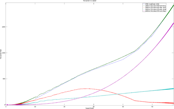
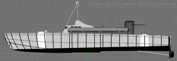
As an example consider the plot below of the towing power (drag times velocity) of a Swedish Navy T21 class MTB as speed increases from 0 to nearly 60 knots. The blue line is from a real tow tank test ("Resultat av släpförsök med svenska patent nr. 109626", A. F. Nordström, Statens Skeppsprovningsanstalt, Göteborg, 1941-10-01) and shows the complex shape of the drag function. One can guess that the curve up to about 10 knots is mostly due to quadratic displacement drag. Above this speed the vessel enters the planing phase and the displacement is reduced as more and more of the weight is supported by the planing forces. This reduces the increase in drag considerably. Finally, from about 38 knots and over another quadratic growth phase takes over. My hypothesis is that this phase is due to the rudders that remain in the water and ought to have (from standard fluid dynamics) a rather small but quadratic drag curve.
The actual physics of planing is very complex and the exact shape of the planing surfaces and the trim of the vessel play a large role in determining the drag (and other forces). The approach taken here to model this in JSBSim is very much simplified, using just a few functions and a handful of tuning parameters to estimate the hydrodynamic forces. For cases where appropriate and comprehensive tow test data exists coefficient tables could instead be extracted from that.

Firstly, the displacement drag is modelled through two functions: one for the hull and one for the rudders. The hull displacement drag is defined as follows:
  <fcs_function name="hydro/displacement-drag-lbs">
   <function>
    <description>Drag due to displacement of hull</description>
    <product>
     <value>0.0000017</value> <!-- Base Cd per lbs buoyancy and ft^2 of hull cross section. -->
     <property>hydro/qbar-psf</property>
     <property>hydro/hull-beam-ft2</property>
     <property>hydro/buoyancy-lbs</property>
     <sum>
      <value>1.0</value>
      <product>  <!-- Increase drag with beta. -->
       <value>10.0</value>
       <abs><sin><property>hydro/beta-rad</property></sin></abs>
      </product>
     </sum>
    </product>
   </function>
  </fcs_function>
There are a couple of things to note:
- The force is scaled by the displacement, so it will decrease as the planing forces increase and lifts the hull towards the water surface.
- The force is crudely increased as the beta angle increases (the drag increases when "side slipping" through the water, but in this case there is no data to base the increment on).
- The Cd per lbs displacement and ft^2 of hull cross section value has been tuned to the graph above, but it was also necessary to modify the static buoyancy/displacement lift function to decrease it faster with speed to get a decent match (among other things this simplified model computes the buoyancy based on the undisturbed water level and, further, at planing speeds the interface between the hull and the water is very different from at slower speeds).
The rudder drag function, on the other hand, is simpler (Cd has been tuned to the graph above while the rudder angle penalty is just guessed):
  <fcs_function name="hydro/rudder-drag-lbs">
   <function>
    <description>Drag due to rudders (not reduced by planing)</description>
    <product>
     <value>0.0036</value> <!-- Base Cd per ft^2 of hull cross section. -->
     <property>hydro/qbar-psf</property>
     <property>hydro/hull-beam-ft2</property>
     <sum>
      <value>1.0</value>
      <product>  <!-- Increase drag with rudder angle. -->
       <value>10.0</value>
       <abs><property>fcs/rudder-pos-norm</property></abs>
      </product>
     </sum>
    </product>
   </function>
  </fcs_function>
The third component of the drag is due to planing. The planing force and moments are computed by the generic hydrodynamic-planing.xml system. The system is based on a (simple) model of planing described in (H. Wagner, "Planing of Watercraft", 1933, translated from German as NACA-TM-1139 in 1948) which models the normal force created by a flat planing surface.
The system is set up by providing geometric information about the location of the planing surfaces (assumed to be 3) in the hydro RP frame and two tuning parameters per surface, a scaling factor for the normal force and an additional skin friction coefficient (per ft^2 of planing surface below the undisturbed water line).
 <system file="hydrodynamic-planing">
  <!-- Parameters defining the planing surfaces of the hull. -->
  <!-- NOTE: Coordinates in the hydro RP frame. -->
  <property value="27.20">hydro/planing/forebody-length-ft</property>
  <property value="14.76">hydro/planing/forebody-beam-ft</property>
  <property value="-7.28">hydro/planing/forebody-keel-z-ft</property>
  <property value="-12.17">hydro/planing/forebody-end-x-ft</property>
  ... <!-- The same set of geometry information for the middle- and afterbody planing surfaces omitted. -->

  <property value="0.95">hydro/planing/forebody-normal-force-factor</property>
  <property value="0.90">hydro/planing/middlebody-normal-force-factor</property>
  <property value="0.85">hydro/planing/afterbody-normal-force-factor</property>

  <property value="0.001">hydro/planing/forebody-skin-friction-coefficient</property>
  <property value="0.001">hydro/planing/middlebody-skin-friction-coefficient</property>
  <property value="0.001">hydro/planing/afterbody-skin-friction-coefficient</property>
 </system>
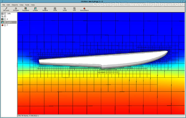
The system outputs lift, drag (Fbx) and side (Fby) forces as well as pitch and roll moments (yaw is missing presently) that need to be added into the corresponding channels of the craft specific hydrodynamics configuration. A visualization of the configuration is shown in the image below.

The integration of the planing drag into the craft specific hydrodynamics configuration is shown below. First the drag from the various surfaces is combined.
  <fcs_function name="hydro/planing-drag-lbs">
   <function>
    <description>Drag due to planing.</description>
    <sum>
     <property>hydro/planing/forebody-induced-fbx-force-lbs</property>
     <property>hydro/planing/middlebody-induced-fbx-force-lbs</property>
     <property>hydro/planing/afterbody-induced-fbx-force-lbs</property>
     <property>hydro/planing/forebody-friction-fbx-force-lbs</property>
     <property>hydro/planing/middlebody-friction-fbx-force-lbs</property>
     <property>hydro/planing/afterbody-friction-fbx-force-lbs</property>
    </sum>
   </function>
  </fcs_function>
Then it is included in the Body-X or drag channel total. Due to a potential implementation problem in hydrodynamics.xml (probably the coordinate frames issues as mentioned far above) the drag was included in the drag channel rather than in the Body-X channel. When included there it should always be positive (while in the Body-X channel it would almost always be negative), hence the added <abs>-element here.
  <fcs_function name="hydro/fdrag-lbs">
   <function>
    <product>
     <property>hydro/active-norm</property>
     <sum>
      <property>hydro/displacement-drag-lbs</property>
      <property>hydro/rudder-drag-lbs</property>
      <abs>
       <property>hydro/planing-drag-lbs</property>
      </abs>
     </sum>
    </product>
   </function>
  </fcs_function>
'To be continued... '
Examples
Examples by the author of the generic systems:
- Malmö Flygindustri MFI-9
- Short Empire
- Gokstad ship
- Swedish Navy T21 class MTB
- https://github.com/andgi/FlightGear-Monitor
- https://github.com/andgi/FlightGear-UB_I
Other aircraft
Known problems
- The hydrodynamic-planing-floats system in FlightGear 2017.1.x and earlier appear to have some wires crossed - the float with the negative y-axis location appears to be on the right side of the aircraft which is not intended. Fixed before 2017.2.x.
- The hydrodynamics planing model often reacts poorly to non-smooth water surfaces (in the terrain mesh, not waves) which is not that uncommon in FlightGear's terrain. Quickly reducing speed may help.
- The hydrodynamics planing model requires a significantly increased FDM rate (the /sim/model-hz property) for good simulation results. This increases the CPU use by JSBSim (which usually is in the low single digit percent before). On some systems this change in CPU use appears to have a considerable impact on the frame rate while on other systems it has no frame rate impact (i.e. CPU isn't the bottleneck).
