Short Empire
 | |
|---|---|
 | |
 | |
| Type | Flying boat, Historical aircraft |
| Configuration | High wing aircraft, Double-deck aircraft |
| Propulsion | Propeller aircraft, Four-engine aircraft |
| Manufacturer | Short brothers |
| Author(s) | Anders Gidenstam |
| FDM | JSBSim |
| --aircraft= | Short_Empire |
| Status | Beta |
| FDM |
|
| Systems |
|
| Cockpit |
|
| Model |
|
| Supports |
|
| Development | |
| Website |
|
| Repository |
|
| Download |
|
| License | GPLv2+ |
|
| |
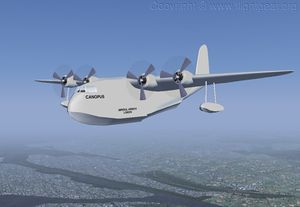
The Short S.23 'C'-class Empire flying boats were designed and built by Short Brothers in 1935 to a specification and order placed by Imperial Airways. A total of 31 Short S.23 flying boats were built, 25 for Imperial Airways and 6 for QANTAS Empire Airways. The first S.23 to fly was Canopus on July 3 1936 and the last was Caledonia, scrapped 23 March 1947. Between those years the S.23 Empire flying boats served a route network stretching (at times) from Foynes (Ireland) in the north-west, Durban (South Africa) in the south to Sydney (Australia) in the south-east. The improved versions Short S.30 (9 built) and Short S.33 (2 built) are also considered as 'C'-class Empire flying boats but are not yet represented in FlightGear.
Cockpit, instruments and controls
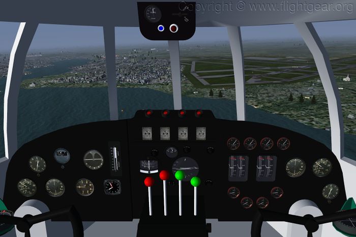
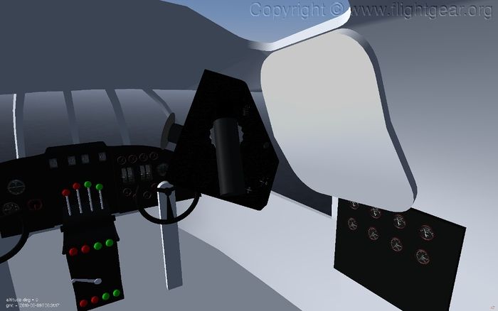
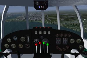
The Captain's and the First Officer's dashboard together with the Throttle box in the middle, with the throttle (top), mixture (middle, not in picture) and propeller pitch (bottom, not in picture) control levers. At the top of the centre part are the engine starter buttons.
Flap control panel
The flap control panel is mounted in the roof above the windscreen. To begin extending/retracting the flaps turn the operating switch towards FLAPS OUT/FLAPS IN. Return the operating switch to the center position once the desired position is reached. The red indicator light is lit when the flaps are beyond the 1/3 setting. The blue pilot light indicates that the flap control system is powered.
Flap settings above 1/3 must no be used for take-off. Maximum speed with fully extended flaps is 115 mph (100 knots).
Fuel system
Close to the roof at the center of the rear bulkhead of the flight deck are the fuel contents gauges and slightly forward in the roof is a control box for the fuel supply control levers. The Short S.23 as delivered came with 3 different fuel system capacities depending on the intended use of the aircraft. The systems were
- Mark I standard/short-range.
- The standard fuel system used on 27 aircraft. There are two 326 (imperial) gallon fuel tanks, one in each wing. The control levers are (left to right) the red lever opens and shuts the supply from the port tank, the black lever opens a balancing line for equalising the tank content (not fully implemented yet) and the green lever controls the supply from the starboard tank.
- Mark II medium-range.
- One outboard 179 and one 326 (imperial) gallon tank in each wing. Used on the aircraft Cavalier and Centarus. The fuel supply control levers and fuel content gauges are in the places as for the Mark I fuel system and in the intuitive order.
- Mark III long-range.
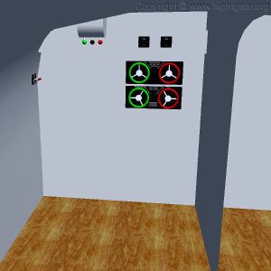
- One outboard 179, one 326 and one inboard 380 (imperial) gallon tank in each wing and two 280 gallon tanks in the hull aft of the flight deck. Used on the aircraft Cambria and Caledonia which undertook a series of trial crossings of the North Atlantic in the summer of 1937. The S.23 could not carry a meaningful payload across the Atlantic. The fuel supply control levers are split between the roof mounted control box and a control box on the port side of the rear bulkhead. On the roof mounted control box the green levers controls the starboard wing tanks, from the right side outboard, middle and inboard, the red levers control the supply from the port middle and outboard tanks. On the port control box the single green lever control the supply from the right hull tank, while the two red levers control the port hull and inboard wing tanks.
In FlightGear the fuel system type is controlled by the selected livery. Unavailable tanks are forced empty.
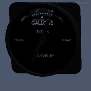
The Televel fuel content gauges are used to measure the tank contents. Wind the handle clockwise to free the probe from the float in the tank, then slowly anticlockwise until the probe hits the float and the scale stops moving. The scale index then shows the current tank content.
| Tank position | Capacity (Imperial gallons) | Mark I | Mark II | Mark III |
|---|---|---|---|---|
| Port wing middle | 326 | X | X | X |
| Starboard wing middle | 326 | X | X | X |
| Port wing outer | 179 | X | X | |
| Starboard wing outer | 179 | X | X | |
| Port wing inner | 380 | X | ||
| Starboard wing inner | 380 | X | ||
| Port side fuselage | 280 | X | ||
| Starboard side fuselage | 280 | X |
All tanks on each side are connected to a common supply point which feed the fuel pumps of the engines on that side. From the engine driven fuel pumps, one at each engine, fuel is feed into a feed line connected to all four engines. There are three fuel pump test cocks inserted into the fuel feed line which can be closed to isolate each fuel pump and engine to verify the operation of the fuel pump. The control for the central fuel pump test cock, which connects the left and right sides of the fuel feed line, is located on the right side of the flight deck just forward of the rear bulkhead. The left and right fuel pump test cocks, which connect the feed line of the inner and outer engine on the respective sides, are controlled by the lower pair of large hand wheels on the rear bulkhead of the flight deck.
Sperry A-2 autopilot
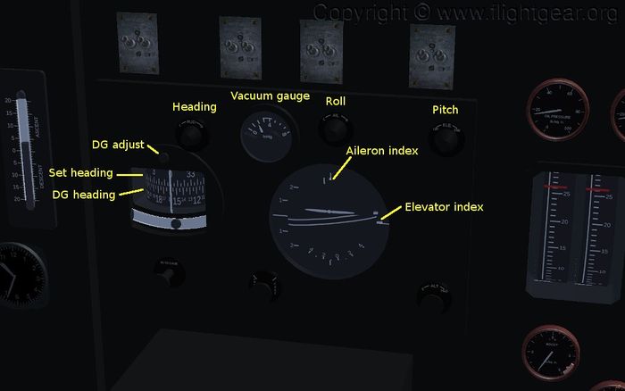
The Sperry A-2 automatic pilot (or gyropilot as the flight manual calls it) is a 3-axis autopilot that provides heading, pitch and roll hold.
Checklist: Engaging the gyropilot
- Check vacuum, 3 - 5 inHg.
- Check oil pressure (not available yet).
- Open speed valves.
- Check the Directional Gyro setting and that both gyros are uncaged.
- Trim the aircraft to fly hands-off.
- Set the follow-up indices to match the current gyro indications.
- Engage the gyropilot. The autopilot engage lever is located above the propeller pitch controls at the rear of the throttle box.
If there is an oscillation on one or more of the controls slowly close the corresponding speed valves until the oscillation stops.
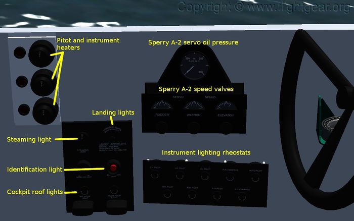
A speed valve should not be closed completely as that will lock the corresponding control. The speed valves are below the window on the port side of the captain's seat. (Note: in FlightGear 2.6.0 or earlier the speed valves are only available via the property browser, in /fdm/jsbsim/sperry-autopilot/ .)
Turns
- Small heading adjustments can be made as flat turns by turning the heading knob slowly.
- For larger adjustments lock the rudder by closing the heading speed valve and turn by setting an appropriate bank via the roll knob. Alternatively, set an appropriate bank via the roll knob and continuously turn the heading knob to keep an appropriate rudder response. Or disconnect the autopilot and fly the turn manually.
Electrical system
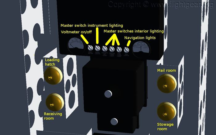
The main electrical switchboard is located on the starboard side to the rear of the flight deck. The switchboard contains the master switches for the instrument lighting and the interior lighting and the switch for the navigation lights. All 6 switches should be on (down) for flight. Below the main unit are 4 brass switches for the rear flight deck lighting.
Most of Imperial Airways' route network had short sectors (and the standard Empire flying boats also had a quite limited range) that were navigated using dead-reckoning supplemented by visual observations and radio direction finding, both by using the loop aerial and by radio bearings measured and reported by ground stations. On the more remote parts of the route network the radio navigational aids were unreliable and few and far between.
On long sectors, and in particular over water, such as on the trial crossings of the North Atlantic, celestial sightings were an important additional input to the navigation process.
In FlightGear the First Officer can use the RAF mk9 bubble sextant available to the right of his seat by clicking on its handle (see also the link under References below). The astro-hatch is likewise opened by clicking on it. The First Officer can walk around the flight deck using the 'W','A','S' and 'D' keys.
The equipment used for radio direction finding is not yet implemented but a reasonable approximation can be had by using the ADF information presented by the nav-training-osd.xml add-on linked under References below.
Handling instructions
Disclaimer: These instructions are derived only from common sense together with certain data from the available records and have no connection whatsoever to any instructions for the real aircraft.
Engine start
- Mixture rich
- Airscrew pitch FINE ⇧ Shift+N
- Magnetos set to both } } }
- Run starter as required on one engine at the time ⇧ Shift+engine#; s (~ to select all engines again)
- The throttle might need to be opened up quite a bit. (Full throttle might currently be needed.)
- The starter performance may be degraded when starting on the aircraft battery (the only supported option so far).
Pre-take off
- Center of gravity within the legal range (See the aircraft help.)
- Verify that all fuel pumps are operating by closing the fuel pump test cocks to isolate the pumps during engine run up. The fuel pump test cocks MUST be opened again before take-off.
- Flaps 1/3. Warning: Flap settings above 1/3 may cause severe porpoising during take-off.
Take off
- The take-off run should be into the wind
- Full power (max 5 minutes)
- Use rudder, aileron and asymmetric thrust as required to make the take-off run straight
- Keep the control column back, take off pitch is about 9 deg
- Minimum getting off speed 78 mph.
- Recommended climb speed at least 120 mph
Cruise
- Mixture rich of peak
- Airscrew pitch COARSE (n)
- Typical cruise speed 165 mph
Landing
- Flaps 1/3 - full as required
- Airscrew pitch FINE (⇧ Shift+N).
- Recommended approach speed 115 mph.
- Beware of water-loops - keep the nose up.
Routes and staging-posts
The prewar Empire Air Mail Scheme (EAMS) in three maps (click to view):
- Southampton, UK - Alexandria, Egypt
- Alexandria, Egypt - Durban, South Africa
- Alexandria, Egypt - Sydney, Australia
These maps are made with the Great Circle Mapper.
Installation and Dependencies
Known problems
- Real weather fetch sometimes cause NaN problems.
External links
- Experimental FlightGear 2.0.0 back-port. Read the install instructions. Note: The most up to date version of the Short Empire is available in FlightGear/git.
- A work-in-progress document on the various routes where the Short Empire Flying boats were used.
- A very short introduction to celestial navigation in FlightGear. The Short Empire flying-boat has the required instruments.
- Add-on on-screen display of compass and directional gyro heading and basic radio direction finding readings.
