Fairchild Republic A-10 Thunderbolt II, OPRF Version
The Fairchild A-10 Thunderbolt II (aka Warthog) offers a wide variety of features and controls. Special features include the ability to simulate ordnance use, and a detailed 3D textured cockpit. Many of the A-10's flight systems are modeled as well, such as support for TACAN.
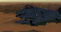
 The "Warthog" | |
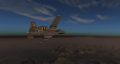
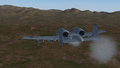
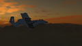
 A-10 Warthog Taking off from KXTA | |
| Type | Military aircraft, Attack aircraft |
|---|---|
| Configuration | Low wing aircraft |
| Propulsion | Twinjet (Jet aircraft, Twin-engine aircraft) |
| Manufacturer | Fairchild Republic |
| Author(s) |
|
| FDM | YASim |
| --aircraft= | A-10 |
| Status | Production |
| FDM |
|
| Systems |
|
| Cockpit |
|
| Model |
|
| Supports |
|
| Development | |
| Repository |
|
| Download |
|
| Wikipedia |
Fairchild Republic A-10 Thunderbolt II |
|
| |
This is the version used by OPRF (Operation Red Flag) and is the branch that is being actively developed.
About the aircraft
The Fairchild Republic A-10, nicknamed "Warthog," is a U.S. single-seat, twin-engine, very robust jet aircraft designed for ground attack.
User's Manual
In the current version, the aircraft simulation begins with the aircraft powered down and damage disabled.
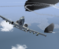
The electrical power systems and the APU's operation are simulated to a large extent. Mid-air refueling is also implemented.
The navigation instruments are TACAN, ILS and also a VHF so you can have homing on a VOR station.
Several external loads are available and the HUD provides a CCIP.
Keybinds
j/k Extend/Retract Speedbrakes
[/] Extend/Retract Flaps
f Slats
e Trigger
Shift+q Flares
Electrical power with APU starting procedure

At FlightGear startup, both electrical power and APU are shut down and there is no external power supplied.
You, might see, early on, some needles spinning back on the engines gauges panel and the VSI ... this is only a software initialization artifact.
So, look at the right console, there is a panel with 6 switches, that's the Main Electrical Control Panel. Hit Ctrl-c and you will have a view of where to click.
Let's connect the battery: switch on the battery switch. A few indicators should light up, but not all of them. Now with the battery connected you can start the APU.
The APU start/stop switch is located near the throttle on the left console. Switch it on. Now check the APU's tachometer and EGT on the engine gauge panel.
If the APU has started successfuly you should see the EGT (Exhaust Gas Temperature) rapidly climb to 800/900 °C and then stabilize when the RPMs reach 60%.

Now the APU has sufficient RPMs to provide electrical power through its generator. So let's turn on the APU generator. This one is on the main electrical control panel, upper left corner of the electrical control panel, right console again.
With the APU generator powered up most of the instruments receive electrical power and now the AOA]] indexer lights up and the HSI (the compass) and ADI (artificial horizon) look much better.
At 85% RPM the APU supplies enough bleed air to start the engines.

Engines starting procedure
Now that we have minimum electrical power and bleed air supplied by the APU, starting the engines is straight forward.
Just click on one of the throttle rails (Ctrl-c to see them), the throttle will move from stop to idle and the engine start. Wait for the starting cycle light to turn off, turn on the corresponding generator and repeat with the second engine.
Now the complete electrical circuit is powered and you can stop the APU to save some fuel. It wont be useful anymore. (This could change with future development of engines failures...)
Fuel System
FlightGear A-10 starts with all internal tanks full.
2 wing tanks (left and right), 2 fuselage tanks: left main (aft) linked to left system and right main (forward) linked to right system, up to 3 external tanks (2 wings and 1 fuselage).
Normally the left wing and left main tanks feed the left engine and the APU. The right wing and right main tanks feed the right engine. The two feed lines can be interconnected by opening the cross feed valve (E switch).
The wing boost pumps (G switch) supply the respective engines until the wing tanks are empty, then the wing boost pumps automatically shut off. The main boost pumps then supply the respective engines with the remainder fuel in main tanks.
In case of a wing tank boost pump failure, the wing tank fuel will gravity feed its respective main tank if the main tank fuel level is below 600 lbs. Check valves prevent reverse fuel flow from the main tanks to the wing tanks.
In case of a main tank boost pump failure, the affected engine will suction-feed from the affected tank for all power setting up to an altitude of nearly 10,000 feet.
Unequal fuel level between left (aft) main and right (forward) main tank (imbalance superior 750 lbs) will cause a longitudinal CG shift that may exceed allowable limits. In this case, opening the valve "tank gate" create a link between the two main tanks.
Fuel from the external tanks is transfered to the wing or main tanks by pressure from the bleed air system. Wing tanks can be topped when the fuel level is below 1590 lbs. Main tanks can be topped when the fuel level is below 3034 lbs. The cycling is repeated until fuel is depleted from the external wing tanks first, and external fuselage tank secondly.
For negative G flight, collector tanks will supply the engine with sufficient fuel for 10 seconds operation at MAX power.
With fully loaded fuel tanks and a full load of armament, the A-10 is heavy--about 50,000 pounds. At this weight the plane is quite difficult to fly. Symptoms you would notice are difficult to take off, difficulty gaining altitude, difficult to manoeuvre without triggering stall warnings or actual stalls.
To avoid these problems, if you choose to equip the plane with full armament you may wish to fill the tanks only half full or so--the plane becomes much easier to fly and half fuel is still enough for a reasonably long flight.

The Fuel Control panel is located on the forward part of left console. 1 lever, 4 push buttons and 8 switches are functional.
- (A) Fill Disable buttons, left and right wings tanks. Here fill disabled (button up showing red stripe). Refuel disabled for the wings tanks.
- (B) Fill Disable buttons, left and right main tanks (practically forward and aft fuselage tanks). Here fill enabled (button down hiding red stripe). Refuel enabled for the main tanks.
- (C) Refuel Receiver Door lever.
- (D) External Tanks switches, Wings and Fuselage. Set to OFF to un-pressurize external tanks
- (E) Cross Feed switch, allow any operating boost pump to feed both engines.
- (F) Tank Gate switch, open a valve linking the left (aft) and right (forward) main fuel tanks.
- (G) Boost Pumps (Wing)
- (H) Boost Pumps (Main)
HUD

The Head Up Display is turned off by default at aircraft startup. To turn it on electrical power on at least one of the three generator is needed as it isn't wired to the battery.
The HUD Control panel is located on the upper left corner of the main instrument panel. Three knobs are functional.
- (A) Mode Selector Switch: Modes available are:
- OFF
- TEST - Currently shows a placeholder "Initializing" screen. In the real aircraft this is used mainly to control the LASTE (Weapon and Navigation system) menu, however this is currently not implemented
- NAV - Standard display, shows speed, altitude, distance and time to next waypoint aswell as navigation to the steerpoint.
- CCIP - Same as NAV with the addition of CCIP (Continuiously Computed Impact Point) weapon symbology
- CCRP - Not Implemented
- EXP - Not Implemented
- STBY - Not Implemented
- (B) INTEN knob: Adjust the HUD luminosity.
- (C) DEPR knob: Not Implemented
HUD Symbology:

- (D) Pitch ladder.
- (E) Indicated Air Speed, Kts.
- (F) Primary Aiming Reticle.
- (G) Horizon Line
- (H) Primary Aiming Reticle Digital index.
- (I) Magnetic Heading Tape.
- (J) Indicated Altitude in feet (ASL).
- (K) Radar Altitude in feet (AGL) followed by letter "R".
- (I) Aircraft Pitch in degrees, boxed.
- (M) Total Velocity Vector indicator.
- (N) Pointer showing the rudders deflection.
Weapons system
Weapons Currently Available:
- LAU-68 (Launcher with 7 High-Explosive rockets)
- Mk-82 (Available in single and triple racks, High drag and Low drag)
- MK-84
- CBU-87
- AGM-64B
- AIM-9M (A/A Missile, available in dual racks)
- AN/ALQ-131 (ECM pod, currently no use)

Be sure to have electric power before trying to use the armament panel. The gun's rounds counter (A) should be lighted in blue and the HUD should be in CCIP mode. This is needed to see targeting symbology for your weapons, there will be no symbology in NAV mode.
First of all push up the Master Switch to ARM (B).
To use the gun, push up the Gun Rate Switch to HI (right of the rounds counter). At the top/left of the main panel a green light indicating 'Gun Ready' will light up. Press e to fire the gun. Aiming is done with the circle on the HUD which will indicate close to where the rounds will land. As you get closer the circle symbology changes to indicate your range. If you are using the gun for Air to Air, switch the AIM-9 Mode Knob to SEL. This will put the weapon system into Air to Air mode and the gunning symbology will change to something more useful for Air to Air use.
To release the Mk-82s and fire the LAU-68s, select the green squares in the center of the weapons panel and press E to fire. Keep in mind that only one type of weapon can be selected at one time, and the order in which you select the pylons will affect the order in which the ordnance on them is released.
To use the AIM-9s, turn the AIM-9 Mode Knob (C) to SEL (click on the right side of the knob). Then select the pylons with AIM-9s mounted. There will be a small circle about a 3rd of the way down the HUD - This is your Seeker. Maneuver the aircraft to place the seeker near an enemy aircraft and if the missile has a good enough lock on it, it will track it and the tone will change to a higher pitched tone. At this point you can fire. It is best to fire within 7 miles if the aircraft is hot, or coming towards you, and around 3 if the aircraft is cold, or going way from you. The other aircraft maneuvering will also affect missile performance so you may want to wait until you ger closer for a higher chance of a likk As soon as you turn the knob past the first mode, OFF, the AIM-9's will start to cool. This takes around 30 seconds. You can still use the AIM-9s in this time however their range and effectiveness in keeping a lock will be reduced. If the AIM-9 system has not been powered on, the missile will not track and will fly unguided and unarmed.
Gallery
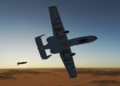
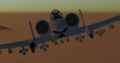
A-10 using its GAU-8 30mm Gun
A-10 in Bombable


Work In Progress
| Task | Status | Remarks |
|---|---|---|
| Rewrite Weapon System handling code | Done! ✅ | |
| Add additional weapon loadouts (something guided? GBU-12/AGM-65?) | CBUs, Mk-82R, AGM-65, Mk-84 and ECM pods have been added | |
| Paintkit fix | Done! ✅ | |
| Weapons Graphical update | Done! ✅ | |
| Full cockpit functionality | Getting there, Maverick screen still needs work... | |
| FDM rework | JSB file is there, just needs some refining and implementation | |
| Canvas HUD rewrite | Done! ✅ | |
| Additional Liveries | Got a lot, thanks to Bat. Still need some more! |
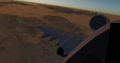
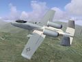
Full load of CBU-87s

See also
External links
- A-10 Development Discord Server: https://discord.gg/RmtjmsT5vS
| |||||||||||||||||