Howto:Add effects to an aircraft
This article is an introduction how to use the Flightgear Effect framework as a contributor - mainly for aircraft, but in principle also for scenery models.
What are effects?
Simply put, effects are instructions for the graphics card how a given surface is rendered. In FG, most effects can be seen as something like configuration files for Shaders (i.e. GLSL code that is directly executed on the graphics card).
Per default, all meshes are processed using a Blinn-Phong shading model which uses a combination of ambient, diffuse and specular lighting. This looks generally acceptable, but does not really capture the properties of many materials.
GLSL shaders on the other hand can (and do) solve much more complicated lighting equations than Blinn-Phong does, taking into account things like environment reflections, Fresnel small angle reflections, diffuse irradiance from skylight, etc. In addition, shaders can also process additional information on structures not captured by the 3d mesh triangles, for instance via normal maps.
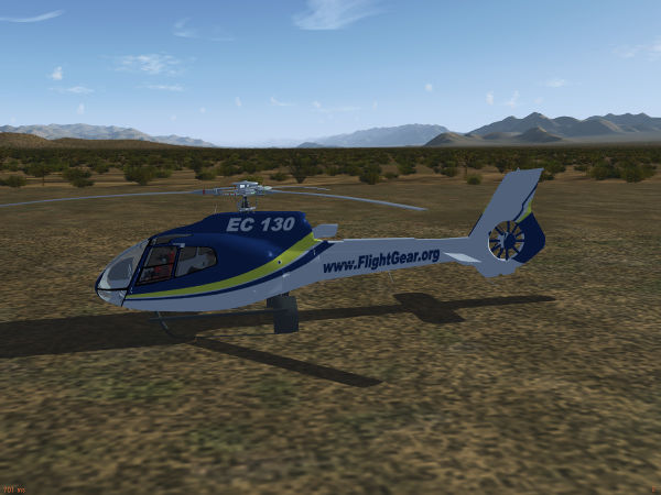
To get a visual idea, compare the following two images (you may have to magnify them to fullscreen to appreciate the details). The first one is processed by a default Blinn-Phong scheme.
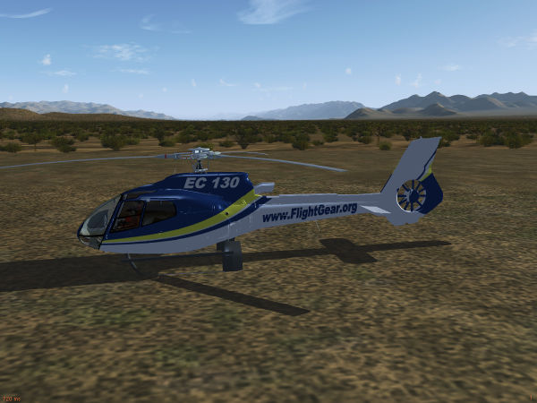
The second one is processed by a shader which utilizes among other things normal and irradiance mapping:
The differences are perhaps subtle, but combine to a much more realistic impression. Thus, effects are what turns a good 3d model into a great 3d model.
Useful concepts
It's worth looking into some things which are specified already at the creation stage of a 3d model (i.e. set by blender or ac3d).
Materials
Materials belong to the Blinn-Phong scheme and tell how a surface looks like when rendered in the scheme. A material is comprised of four different colors, each as (rgb) triplets. The ambient color channel is multiplied with the scene ambient light and determines what in what color surfaces in shadow appear. The diffuse color channel is multiplied with the scene diffuse color and determined how surfaces in light appear, and the specular color channel is multiplied with the scene specular color and determines the color of specular highlights. Finally, the emissive color channel determines a color independent of the scene light.
In addition, a material has a transparency which determines to what degree one can see through the surface and a shininess which determines how glossy the surface looks (i.e. how narrow the specular highlights appear).
The end color of a pixel in Blinn-Phong is determined by summing all channels and multiplying with the texture color. Thus, textured models should not use colored materials (or the texture won't appear in its natural color). Generally it is a good idea for textured models to use a white diffuse color (1,1,1) in the material and a grey ambient with a value of 0.3 to 0.5 according to the desired darkness of shadows. The specular color should usually be white (1,1,1) too, unless there's a compelling reason not to (a metallic material where specular color should match the diffuse color, or a lighter shade thereof). The most common mistake for beginners is to neglect the ambient channel, in which case shadows tend to appear too bright, or to assign an emissive color which makes the model glow at night.
The way Flightgear treats models, each surface (face) can have one (and only one) material assigned - make sure you understand what it is and how to alter it in the 3d modeling tool of your choice.
Objects
Objects are parts of a 3d model which are grouped together. They consist of a mesh, material[s] assigned to the faces of that mesh and, optionally, the texture associated with it. They have a unique name assigned. In the FG effect framework, an effect is always assigned to an object.
The relevance of grouping into objects is that the graphics card processes models in so-called draw calls. Before each draw call, the so-called state set needs to be prepared (mainly texture sheets, material parameters and positioning matrices configured by animations) and this costs some time. The net effect is that it is far faster to render a million vertices in one draw than in thousand draws a thousand vertices each. Due to the limitations of the AC3D model format used by FlightGear, different parts of an object cannot be assigned to different texture sheets, thus for each extra texture sheet there will be an extra object and ultimately an extra draw call, having as a result that four 1k texture sheets are less efficient than the same data on a single 2k texture sheet because there's 4x less draw calls.
| Note Anything that can be combined into one object also should be combined into one object, and the number of texture sheets used should be as low as possible. |
Make sure you understand how to group things into objects and assign object names in the 3d modeling tool of your choice.
UV-mapping
The relationship which part of a surface is colored by which part of a texture sheet is called uv-mapping. The map is defined as part of the 3d modeling process.
One limitation of how FG treats models is that a surface can only have one uv-map defined (but potentially up to eight textures). This means that all textures assigned to a surface have to share the same uv-map.
Conceptually the uv-mapping can be done uniquely (i.e. every surface is mapped to a different part of the texture sheet) or shared (some or all surfaces are mapped to the same part of the texture sheet). Consider for instance screws on a panel - in principle it's sufficient to have one picture of a screw on the texture sheet and assign hundred screws to use it - this saves a lot of work and texture space.
Whether this becomes a problem later or not depends on what you want to achieve - consider for instance a lightmap which defines how much light falls onto a part of a surface. If you share the texture space of the screw, it automatically means that also the light falling onto each of them will be the same in the effect, and usually that's not desirable.
Thus, if you want to use all the options of the effect framework, you can usually not share texture space between different surfaces, the mapping needs to be unique.
| Note Plan ahead what effects you want to use and design your uv-mapping accordingly. |
Accessing the framework using inheritance
Assigning an effect
Using an effect is designed to be easy and xml-configurable. Generally it's a two step process, consisting of
- defining a derived effect
- assigning the derived effect to an object
Let's go through these in detail:
The main concept used in defining effects is inheritance. The way this works user-side is that there are parent and child effects, and any parameter defined in a child effect overwrites whatever is defined in the parent effect for that parameter.
All effects available have a master configuration file in $FGData/Effects (where in turn inheritance may be used). To create a derived effect, an effect file needs to be created (say, Aircraft/MyAircraft/Models/Effects/myeffect.eff) with a an inheritance definition of a master effect. A minimal file could be
<?xml version="1.0" encoding="utf-8"?>

<PropertyList>
  <name>myeffect</name>
  <inherits-from>Effects/model-combined-deferred</inherits-from>
</PropertyList>
Objects can now reference this effect, which in turn will reference Effects/model-combined-deferred.eff (note that .eff is not appended to the inheritance line). This is not very interesting because nothing has happened to far - but it gets interesting as soon as a <parameters> section is appended to the file which sets configuration options.
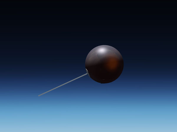
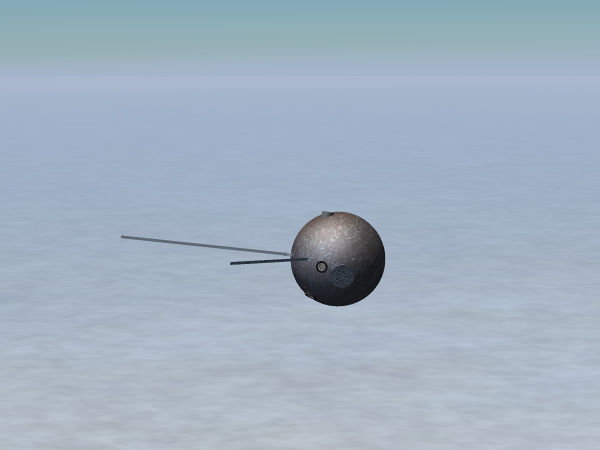
As a complete example making use of many different parameters, here's the effect rendering the Vostok capsule
<?xml version="1.0" encoding="utf-8"?>

<PropertyList>
  <name>vostok-heat</name>
  <inherits-from>Effects/space-combined</inherits-from>

  <parameters>
  	<texture n="3">
		<image>Aircraft/Vostok-1/Models/Spacecraft/heatmap.png</image>
		<type>2d</type>
		<filter>linear-mipmap-linear</filter>
		<wrap-s>clamp</wrap-s>
		<wrap-t>clamp</wrap-t>
		<internal-format>normalized</internal-format>
	</texture>

	<texture n="4">
		<image>Aircraft/Vostok-1/Models/Spacecraft/scorchmarks.png</image>
		<type>2d</type>
		<filter>linear-mipmap-linear</filter>
		<wrap-s>clamp</wrap-s>
		<wrap-t>clamp</wrap-t>
		<internal-format>normalized</internal-format>
	</texture>

	<texture n="5">
        <type>cubemap</type>
        <images>
            <positive-x>Aircraft/Generic/Effects/CubeMaps/fair-sky/fair-sky_nx.png</positive-x>
            <negative-x>Aircraft/Generic/Effects/CubeMaps/fair-sky/fair-sky_px.png</negative-x>
            <positive-y>Aircraft/Generic/Effects/CubeMaps/fair-sky/fair-sky_ny.png</positive-y>
            <negative-y>Aircraft/Generic/Effects/CubeMaps/fair-sky/fair-sky_py.png</negative-y>
            <positive-z>Aircraft/Generic/Effects/CubeMaps/fair-sky/fair-sky_nz.png</positive-z>
            <negative-z>Aircraft/Generic/Effects/CubeMaps/fair-sky/fair-sky_pz.png</negative-z>
        </images>
    </texture>

    <darkmap-enabled>2</darkmap-enabled>
    <darkmap-factor>0.4</darkmap-factor>
    <delta_T><use>/fdm/jsbsim/systems/temperature/plasma-T-K</use></delta_T>

    <dirt-enabled>1</dirt-enabled>
    <dirt-color type="vec3d" n="0">0.27 0.21 0.18</dirt-color>
    <dirt-factor type="float" n="0"><use>/fdm/jsbsim/systems/temperature/char-factor</use></dirt-factor>
    <reflection-enabled type="int">1</reflection-enabled>
    <reflection-dynamic type="int">1</reflection-dynamic>
    <reflect_map-enabled type="int">0</reflect_map-enabled>
    <reflection-correction type="float"><use>/fdm/jsbsim/systems/temperature/char-refl-correction</use></reflection-correction>
    <reflection-rainbow type="float">0.05</reflection-rainbow>
    <reflection-fresnel type="float">0.1</reflection-fresnel>
    <ambient_correction>0.1</ambient_correction>

  </parameters>

</PropertyList>
As can be seen from the example, the configuration parameters set can be numbers (both float and int), vectors or textures (the types 2d and cubemap are most common, but also 1d and 3d are possible).
Your derived effect is then assigned to an object inside the xml-wrapper of the model file (i.e. where the mesh is included). The assignment needs to be done to a number of objects specified by name (if you liberally created objects in the mesh, the list may become very long).
<effect>
	<inherits-from>Aircraft/Vostok-1/Models/Effects/vostok-heat</inherits-from>
		<object-name>CapsuleHull</object-name>
</effect>
And that's all that it takes to render a model using an effect.
To really make use of this, you need to know what parameters are available and what parameter does what. This information is best obtained from reading the documentation for the effect (see below for the most common choice).
Some details
Let's consider again the above example. There's different kinds of parameters set. For instance
<dirt-enabled>1</dirt-enabled>
switches an option on. The parameter is set to zero in the master effect, and in order to use dirt mapping in the derived effect, it needs to be switched on. Note that switches are typically intergers or bools, so make sure this does not assign 1.0 here. If a function is switch-controlled, it doesn't matter what parameters or textures you assign for it as long as the switch is off (the branch in the shader won't be executed).
Another important use case is illustrated by
<delta_T><use>/fdm/jsbsim/systems/temperature/plasma-T-K</use></delta_T>
here the floating point parameter gets pointed to a property rather than a constant value via the <use> tag - in this way, it can be changed runtime. You can do this with all integer or float parameters, but not with vectors or textures, these are never runtime switchable.
| Note Unfortunately, so-called tied properties won't be passed properly with this technique (and that includes all properties computed by JSBSim systems) - they need to be passed through a property rule or a Nasal script to properly register. |
The next example shows how a texture is passed.
  	<texture n="3">
		<image>Aircraft/Vostok-1/Models/Spacecraft/heatmap.png</image>
		<type>2d</type>
		<filter>linear-mipmap-linear</filter>
		<wrap-s>clamp</wrap-s>
		<wrap-t>clamp</wrap-t>
		<internal-format>normalized</internal-format>
	</texture>
Unless you know exactly what you're doing, the only things you need to alter for models in your own derived files are the index (here n="3") and the string inside the <image> tag which points to the texture file. The meaning of the index is characteristic for the effect being used and explained in the documentation of it.
Finally, if you ever need to set a vector, this is exemplified by the following line
<dirt-color type="vec3d" n="0">0.27 0.21 0.18</dirt-color>
all color values are just written next to each others, separated by blanks. As mentioned above, no <use> tag is legal here.
| Note All parameter names need to be spelled exactly as in the master effect or they won't replace the defaults. There will be no warning message if that happens, it is legal to declare parameters but not use them in an effect. Thus, double-check your derived effect for typos. |
Animations
Don't forget that some visual properties are not configured via the effect framework but by animations. For instance the material animation can be used to change ambient, specular, diffuse or emissive colors runtime or alter the shininess or transparency. A texture animation can be used to affect textures.
While these animations affect what an effect does, the difference to parameters passed in an inherited effect is that these affect only the chosen effect, whereas animations affect all effects equally. This is relevant because a user might not actually use the effect you are configuring by asking FG to render on a low quality level - he won't see your effect parameters then, but he will see animations.
Warnings
The way the effect framework is intended to be used is to introduce only a <parameters> section in a derived effect and set there whatever is different from the master effect.
In actual reality, inheritance can also be used to alter other parts of the effect file, and in the past this has been used for various hacks (using effects across rendering frameworks, overriding user settings,...).
While none of these hacks are good practice, some of them are harmless as such (i.e. will probably just mean your work isn't future-proof). Others (such as overriding user settings) are considered dangerous because they can potentially render FG inoperable for a user or lead to very exotic bugs and are not accepted on FGAddon.
In any case, if you modify any section of an effect other than <parameters> in a derived effect, you're on your own and can not expect support.
What effect to use?
The effect framework offers a round dozen of different effects which could potentially be used for models, so to a beginner the choice what particular effect to use might not seem so easy - but in actual reality it usually is.
Legacy effects
As of summer 2017, Flightgear offers three main rendering frameworks - classic, Rembrandt and ALS. Since the user may be running any of these, the aim should be to avoid effects which do not play nice with one of them.
This disqualifies effects which have been developed before ALS and Rembrandt were introduced and are kept only for compatibility purposes (and may in fact be discontinued in the future). These are bumpspec.eff, chrome.eff, reflect.eff, reflect-bump-spec.eff and lightmap.eff.
There is nothing these effects can do the modern effect can not, but they will only work properly with the classic renderer. For instance using ALS, in low light they will generate lighting mismatches and in dense fog the fogging will appear wrong.
| Caution Do not use these legacy effects any more. |
Opaque surfaces
The standard workhorse for all three rendering frameworks is model-combined-deferred.eff, and when in doubt, you should likely use this effect (which will be described in detail below). It offers optional normal mapping, environment reflections, specular mapping, light mapping and dirt mapping for all three frameworks.
ALS offers in addition some specific extensions to the model effect (such as grain mapping and rain splashes) as well as a special purpose effect for interior surfaces which doesn't do fogging but can simulate shadows, implicit lightmapping or caustics from glass canopies. This effect falls back to artifact-free defaults for the other renderers.
Transparent surfaces
Due to the way rendering is organizes (in particular the z-buffering technique used to not waste processing power on invisible objects, it is not sufficient to just make a surface transparent to see it rendered correctly - it needs to use a dedicated effect for this to work. For Rembrandt, using a special effect is an absolute must as otherwise surfaces will appear fully opaque.
It also is generally a good idea to make glass surfaces single-sided and use a different surface to represent the outside of a window (with normals pointing outward) than the inside (normals inward).
The minimal choice for transparent surfaces is model-transparent.eff, however this falls back to minimal graphical processing and might lead to bad lighting with ALS and is not recommended. Rather, glass.eff works for ALS seen from the inside and falls back to model-transparent.eff for the other renderers.
For glass surfaces seen from the outside, model-combined-transparent.eff should be the tool of choice which again is the workhorse for all three renderers.
| Caution Do not use effects for opaque surfaces on transparent surfaces. |
Using model-combined-deferred
Since you're most likely to use this effect, let's go through an example in detail and consider how the fuselage effect of the EC 130 is set up (you can see the complete derived effect here).
Normal mapping
A normal map allows to introduce fine structures on a surface which are not on the mesh. Light behaves as if it feels these surfaces, so you can see them unless under very shallow angles which gives the surface the appearance of being structured.
For this, you need a texture (the normal map itself) which contains the local change of the surface normal. This information is encoded in the (rgb) channels of the map - which leaves the alpha channel of the texture. In the model-combined-deferred effect, this alpha channel serves as specular map indicating where reflection happens (see below).
In addition, normal mapping requires mesh tangents and binormals and FG needs to be asked to generate them and make them available to the effect.
The section which needs to be included in the derived effect file at root level to properly process tangents and binormals is (and this is always the same, independent of the particulars of your model - you can just cut/paste it):
  <generate>
    <tangent type="int">6</tangent>
    <binormal type="int">7</binormal>
  </generate>

  <technique n="4">
    <pass>
      <program>
        <attribute>
          <name>tangent</name>
          <index>6</index>
        </attribute>
        <attribute>
          <name>binormal</name>
          <index>7</index>
        </attribute>
      </program>
    </pass>
  </technique>

  <technique n="7">
    <pass>
      <program>
        <attribute>
          <name>tangent</name>
          <index>6</index>
        </attribute>
        <attribute>
          <name>binormal</name>
          <index>7</index>
        </attribute>
      </program>
    </pass>
  </technique>

  <technique n="9">
    <pass>
    <program>
      <attribute>
      <name>tangent</name>
      <index>6</index>
      </attribute>
      <attribute>
      <name>binormal</name>
      <index>7</index>
      </attribute>
    </program>
    </pass>
  </technique>
The specific block inside the <parameters> section configuring the normal map is
    <normalmap-enabled type="int">1</normalmap-enabled>
    <normalmap-dds type="int">0</normalmap-dds>
    <texture n="2">
      <image>Aircraft/ec130/Models/Effects/bumpmap.png</image>
      <filter>linear-mipmap-linear</filter>
      <wrap-s>repeat</wrap-s>
      <wrap-t>repeat</wrap-t>
      <internal-format>normalized</internal-format>
    </texture>
First the normal map function is switched on by setting the enabled flag to 1, then the effect is told that the normal map texture file is not dds (unfortunately that has a sign difference, so the flag needs to be set if you work with a dds sheet) and finally the actual normal map is set with an index of n=2.
The only things you need to adapt when using the effect yourself is the path to the normal map texture sheet and, if your sheet happens to be a dds file (not recommended) the flag needs to be 1.
Light mapping
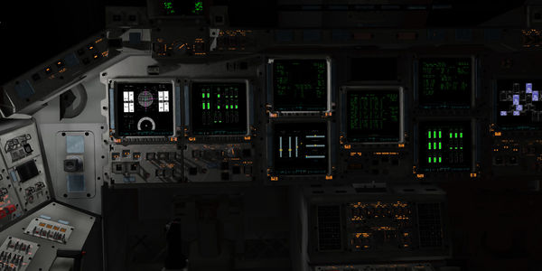
A lightmap is used to illuminate surfaces according to a pre-computed distribution of light, which can give extremely realistic appearances:
(for how to pre-compute a lightmap using blender, see here).
For a lightmap, one needs a texture to describe where the light falls, a color vector for the light and a strength parameter to switch the light on/off or dim it.
The effect supports two different encoding schemes.
For a single channel map, the lightmap texture pixel color is used to define the base color of the light and this gets multiplied by the vector lightmap-color. You can hence leave the color vector at default and just have the texture carry the color information.
For a multi-channel map, the pixel color in each (rgba) channel is used to determine the amount of light (i.e. this supports four different light sources), and the colors and intensities need to be set for each of them. This is what the example below does.
  <lightmap-enabled type="int">1</lightmap-enabled>
  <lightmap-multi type="int">1</lightmap-multi>
  <lightmap-factor type="float" n="0"><use>/systems/electrical/outputs/beacon-itensity</use></lightmap-factor>
  <lightmap-color type="vec3d" n="0"> 1.0 0.0 0.0 </lightmap-color>
  <lightmap-factor type="float" n="1"><use>/systems/electrical/outputs/taxi-light-itensity</use></lightmap-factor>
  <lightmap-color type="vec3d" n="1"> 1.0 1.0 1.0 </lightmap-color>
  <lightmap-factor type="float" n="2"><use>/systems/electrical/outputs/landing-light-intensity</use></lightmap-factor>
  <lightmap-color type="vec3d" n="2">1.0 1.0 1.0 </lightmap-color>
  <lightmap-factor type="float" n="3">0.0</lightmap-factor>
  <lightmap-color type="vec3d" n="3">1.0 0.0 0.0 </lightmap-color>
  <texture n="3">
      <image>Aircraft/ec130/Models/Effects/Lightmaps.png</image>
      <filter>linear-mipmap-linear</filter>
      <wrap-s>clamp</wrap-s>
      <wrap-t>clamp</wrap-t>
      <internal-format>normalized</internal-format>
   </texture>
First the lightmap is enabled, then the multi-channel encoding is selected, and then lightmap-factor (intensity) and lightmap-color are set for four different indices n=0 to 3, utilizing the <use> tag to instruct FG to read the lightmap strength from properties to make lights on/off runtime.
Finally, the lightmap texture is defined under the index 3 (each map has its characteristic index, so if you would use n="2" here, you would instruct the effect to use your lightmap as normal map which generally looks odd).
Reflections
The effect framework does not support reflections of the real environment on a mirror-bright fuselage (which would be fairly costly to compute in the first place). Rather, reflection effects are based on creating the impression that there is something real reflected.
In order to configure the reflection options, one needs to have an idea about what should be reflected, and where should the reflection occur.
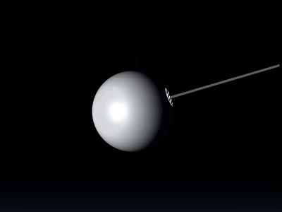
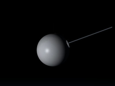
The simplest possibility for the 'what' is the sun and to the 'where' is everywhere - this is how Blinn-Phong works, the bright specular highlights represent the reflection of the light source (in FG the sun). The shininess parameter which determines the size of the highlight then represents the surface smoothness - for a very smooth surface, the reflection is exact and the sun will show as a mirror image, for some surface roughness the reflection will grow in size but lose intensity as microscopic parts of the surface will fulfill the reflection condition also far from the actual mirror image - basically rough surfaces blur reflections, and this is what the shininess parameter does for the sun image.
The following images show the difference between shininess 32 and shininess 128 (the maximum):
Note how the reflection highlight shrinks - but how the surface away from the highlight doesn't reflect anything but keeps its grey color.
If not the whole surface is supposed to reflect but only parts of it (think of windows painted onto a fuselage texture), then the effect needs to be told what parts reflect - this information is encoded in a reflection map.
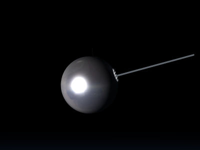
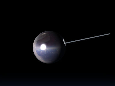
To make the appearance more realistic, in addition to the sun the surface can also be made to reflect an environment. This is done by placing the whole model into a large virtual cube, with the inner cube faces painted by textures of the environment - this so-called cube map is then what appears as the reflected image. For imperfect reflections like on a shiny fuselage, this usually is sufficient (for an actual mirror, the discrepancy to the real environment it would not). There's a couple of environment cube maps available at $FGData/Aircraft/Generic/Effects/CubeMaps (and in a different format at $FGData/Aircraft/Generic/Effects/CubeCrosses) but you can always bring your own. Especially for reflections on rough surfaces where the reflected image is blurred, this might be necessary - the effect framework can not blur reflections dynamically at runtime, so using a custom-blurred cube map is the tool of choice.
The following images show cube map reflections for different reflectivity:
Observe how the environment reflection replaces the base texture color for high, mirror-like reflectivity.
| Note The environment cube map can not be changed runtime, so the choice of the map has to work in every phase of flight. Thus, agressively optimizing the map e.g. for a plane on the runway might lead to poor results at cruise altitude and vice versa. There is no way to get the environment reflection 'right' using a cube map, the idea is to get it plausible. |
Thus, the basic ingredients to cook a reflection effect are reflection map, cube map and the switches to enable them. Another important switch for the cube map is whether the reflection is dynamic or static.
While the reflected image will always change with the eye point, this switch governs whether the reflection will also change with the aircraft orientation. For a reflection of e.g. the inside of the aircraft in the canopy glass, this flag needs to be off because the reflected environment moves with the aircraft - for the reflection of the outside environment in the fuselage the flag needs to be on. For any 3d model that is not the aircraft, the flag needs to be off because the reflection has nothing to do with the aircraft attitude at all.
Now, let's take a look at the reflection definitions of the EC 130 to see it all in action.
<reflection-enabled type="int">1</reflection-enabled>
<reflect-map-enabled type="int">1</reflect-map-enabled>
<reflection-correction type="float"><use>/sim/rendering/refl_correction</use></reflection-correction>
<reflection-dynamic type="int">1</reflection-dynamic>
<texture n="4">
	<image>Aircraft/ec130/Models/Effects/greymap.png</image>
		<filter>linear-mipmap-linear</filter>
		<wrap-s>clamp</wrap-s>
		<wrap-t>clamp</wrap-t>
		<internal-format>normalized</internal-format>
	</texture>
	<texture n="5">
		<type>cubemap</type>
		<images>
		<positive-x>Aircraft/Generic/Effects/CubeMaps/real.blue-sky/fair-sky_px.png</positive-x>
		<negative-x>Aircraft/Generic/Effects/CubeMaps/real.blue-sky/fair-sky_nx.png</negative-x>
		<positive-y>Aircraft/Generic/Effects/CubeMaps/real.blue-sky/fair-sky_py.png</positive-y>
		<negative-y>Aircraft/Generic/Effects/CubeMaps/real.blue-sky/fair-sky_ny.png</negative-y>
		<positive-z>Aircraft/Generic/Effects/CubeMaps/real.blue-sky/fair-sky_pz.png</positive-z>
		<negative-z>Aircraft/Generic/Effects/CubeMaps/real.blue-sky/fair-sky_nz.png</negative-z>
		</images>
	</texture>
<reflection-fresnel type="float">0.01</reflection-fresnel>
<reflection-rainbow type="float">0.2</reflection-rainbow>
<reflection-noise type="float">0.01</reflection-noise>
The first flag enables environment reflections, the second flag enables the use of a reflection map texture. The reflection map texture is passed as the alpha channel of the texture with index 4, with 0 (fully transparent) representing no reflection and 1 (fully opaque) representing full mirror-like reflection. The reflection-correction parameter is in essence added to the reflectivity encoded by the texture and can be used to dynamically strengthen or reduce the reflectivity. The third flag finally sets the reflection dynamic as appropriate for a reflection effect for the fuselage.
Note that there is an alternative encoding scheme when reflect-map-enabled is set to 0. If reflections are enabled, in this case surface reflectivity is assumed to be proportional to the shininess (with shininess 128 representing full reflectivity), to which the reflection-correction is again added. If a normal map is enabled, the alpha channel of the normal map texture can be used to modulate this shininess-derived reflectivity, where then 1 (fully opaque) represents reflectivity according to shininess, and 0 (fully transparent) means no reflection.
The environment cube map itself is defined under the texture index 5, with images for the six faces of the cube being assigned to the six coordinate directions.
The last three parameters control diffraction fringes (mainly relevant for glass in the transparent version of the effect) and noisiness and are a bit beyond the scope of this introduction - you can just play with them.
| Note The effect framework does not play nice with the livery system - while the base texture of an aircraft can be changed runtime, a reflection map can not. Thus, having dull and highly reflective liveries for the same aircraft is somewhat problematic and can only partially be handled using the reflection correction parameter (which can alter overall reflectivity, but not target particular reflective spots). |
Dirt
(note that there is an alternative way using canvas to apply dirt dynamically)
Finally, the effect also allows you to dynamically add discolorations to a texture. Dirt mapping works similar to light mapping - there is a texture map for the distribution of dirt (in this case the (rgb) channels of the reflection map texture sheet serve the purpose), a parameter governing the strength of the dirt admixture for each channel and a color vector for each of the dirt channels, along with the enabling and the multi-channel flags.
As an example, here is a dirt map used to simulate char on the shiny fuselage of the Vostok aircraft after it has entered the atmosphere.
Note that in addition also a material animation has been used to lower shininess.
The relevant part of the Vostok capsule char definition due to entry heat is
<texture n="4">
	<image>Aircraft/Vostok-1/Models/Spacecraft/scorchmarks.png</image>
	<type>2d</type>
	<filter>linear-mipmap-linear</filter>
	<wrap-s>clamp</wrap-s>
	<wrap-t>clamp</wrap-t>
	<internal-format>normalized</internal-format>
</texture>


<dirt-enabled>1</dirt-enabled>
<dirt-color type="vec3d" n="0">0.27 0.21 0.18</dirt-color>
<dirt-factor type="float" n="0"><use>/fdm/jsbsim/systems/temperature/char-factor</use></dirt-factor>
This requires the dirt distribution to be encoded in the red channel - if the green and blue channel are also to be utilized, colors and factors need to be set for them and dirt-multi needs to be set to 1 in addition.
Troubleshooting
You typed your derived effect, assigned it to your objects, start FG and... nothing happens. What now? Here's some tricks and tips to help understand what's going on.
- check that the model shader quality level is high enough
You can define a high-quality shader all day long, but if it is disabled in-sim, you won't see any changed regardless of what you edit. So always check the rendering settings first.
- enable --log-level=warn and search the console or the log file for errors
If you made a typo in the effect name you want to inherit from, FG will print log messages that the parent effect could not be found. If you see such a message, check spelling and especially also paths to the file - and remember that .eff is added automatically, if you insert it into the <inherits-from> tag, you'll be searching for the wrong file.
Also, all GLSL model shaders should be well-tested on multiple platforms by now, but if you see an error message which mentions 'compile error' in combination with 'vertex' or 'fragment', it indicates that a shader is not working. You can not fix this with effect xml, it needs to be reported as a bug (including the full error message).
- assign a 'wrong' effect to see whether anything happens at all
It's sometimes hard to see subtle changes in a reflection map - but if you temporarily inherit from, say, Effects/water, then you'll see whether you are looking at the right surfaces because the visual change is rather drastic (assuming you have the water shader enabled of course...). It happens surprisingly often that one assigns an effect to the wrong surface - in which case nothing ever seems to happen, this is a quick way to check.
- start from a working example
If you're new to effect writing, start from a working example and modify it step by step, check every time what happens. There are many aircraft on the repository which demonstrate how the effects can be used - learn from them. It's much easier to modify something gradually than to write a complete effect definition from scratch and get it correct.
Sometimes you do see output, but it appears wrong:
- the model appears all too dark and the normal map doesn't work
That's usually caused by either forgetting to generate and attach tangents and binormals (see above), or it may be a flaw in the mesh itself which has the normals pointing inward - the 3d modeling application of your choice usually has a way to visualize normals and to reverse them for a surface.
- the rendered model looks weird
Check the assignment of textures to indices - if you try to render your specular map as normal map and vice versa, you will get weird results.
