Howto:Use the normal map effect in aircraft
| Caution
The model-combined effect shader has replaced the separate normal map effect shader. The separate normal map effect shader should be considered deprecated and should not be used for new development. |
FlightGear 2.0.0 introduced effects, a powerful way to use shaders within FG without having to write C code. As of March 2010, FlightGear Git has a normal map effect (Effects/bumpspec.eff), which provides both bump mapping and specular mapping. This howto provides a tutorial on using this effect for aircraft. Similar techniques can be used to use other effects on aircraft.
If you don't know how a normal map works, have a look here.
The latest documentation on the FlightGear effects system is to be found in $FG_ROOT/Docs/README.effects.
Creating the normal map
To create the normal map, there are two options.
- We can use a plugin that can convert a 2D texture representing height to a set of normals. There is a good normalmap plugin for GIMP available. Those on Ubuntu should be able to install it directly from the package manager.
- On the other hand, we can create a high polygon density model of the object in a 3D editor, and generate the normal map from this model. You can find more information on this approach , applied to blender, here
Lets see the 2D approach first:
Once you have the GIMP plugin installed, create the normal map as follows.
- Identify an object that you intend to apply the normal map to using Blender AC3D etc.
- Find the part of the texture (the texture coordinates) that apply to the object. Given that most aircraft textures are sensibly organized, this should be straightforward. The same texture coordinates will be used for the normal map.
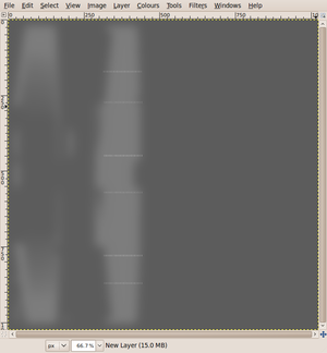
- Open the texture in GIMP and create a new layer with black as the background color. We'll use the existing texture as a guide to creating the normalmap.
- Adjust the opacity of the new layer so you can see the texture underneath. This layer will be a height map, with black representing low points, and white representing very raised points. So, at the moment the entire height map is at sea level.
- Now use whatever painting technique you wish to draw the height. If you want well-defined edges, draw using a sharp-edged tool.
- Once you are satisfied with your height map, delete the background layer, increase the opacity back to 100% and save it as a new file.
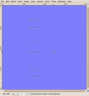
- Now we need to convert the height map to a normal map. To do this, use Filters->Map->Normalmap. If this is not present, you haven't installed the normalmap plugin as described above.
- The default options will work fine, except that you should invert the Y axis (as OpenGL vectors origin is the bottom left rather than top left). However, the author of the plugin recommends the Prewitt 5x5 filter. Once you are happy with the options, press OK, and your image should turn generally blue, but with some strange colours around the areas that you coloured white. This is the normal map.
- Optionally, modify the transparency of the map to alter shininess. Fully opaque texture means maximum shininess. Fully transparent means no shininess, but often other channel are also erased, so to not loose the normal information, always keep a little bit of opacity. You can alter the texture with the eraser tool or use a layer mask. You may want to try to use a noise pattern in the layer mask to simulate dirt and wear on the airframe.
- Save off the normal map as a new png file in your aircraft directory, remembering the correct path.
Now lets see the 3D approach
( this method is independent of the above instruction, and can be done apart )
- In Blender, you created a low poly count model. This is the one that will be exported to FlightGear. Let's call it "low poly"
- Create a UV mapping for this object ( edit mode, select all, U ), then associate a new image to this UV mapping ( UV/image editor, new )
- Duplicate the "low poly" object, and call the new copy "High poly".
- Add details to the "high poly" model, where needed. ( don't MOVE the new copy ! This methods needs that both copies share the same center to work. You could use layers to clarify the viewport when working). You could use "multires", or subsurf modifiers, or you could even do the job by hand. The sculpture tools of blender can be handy too. The workflow depends only on your habits !
Once you are satisfied with the detail level of the "high poly" copy, it is time to create the normal map from this copy, and to transfer it to the "low poly" copy. Blender's powerful interface allows to do this in a single operation :
- In object mode, FIRST select the "high poly" object, THEN "SHIFT-select" the "low poly" object to add it to the selection.
- In the "scene" buttons ( F10 ) , click on the "bake" tab, and make sure you check the "selected to active" and "normals" options. In the menu under "dist" and "bias", choose 'tangent' as the normal space. You can leave 'quad split auto' at the bottom.
- It is wise to specify a bleeding margin in the "margin" option, to ensure the texture will cover the faces entirely. A dozen pixels is usually enough for FG.
- When everything is set, click the big "bake" button. If you followed the instructions carefully, you should see your normal map appear in the UV/image editor. Save it as a png file, and remember where you saved it.
Unfortunately, the space axes of blender and those of the FlightGear shader are different... You will need to invert the X and Y axes of your normal map, or the effect will look inverted. This is easy :
- Open your normal map in GIMP, and go to "Colors -> Components -> Decompose". Choose the RVB option, and "decompose as layers". Validate.
- In the new image that opens, invert the values in the RED and GREEN layers.
- Again, go to "Colors -> Components", but now, "Compose". Choose the RVB option.
- A new image opens, quite similar to the original, but with slight differences. Save this image.
While the main blue tone remains, if you look closely , you will notice that the red and green levels have been inverted. Your normal map is now ready to be used by the FlightGear shader.
Despite it is more complex, this method allows to generate complicated displacement effects, in a much more accurate way than using converted relief maps. This way it is possible to work on 3 axes, to simulate folds, concave zones, etc...etc, all this keeping total control on the desired effect amount, just be sculpting the high poly model accordingly. You can see an image tutorial of this technique here
Creating the normal map Effect
Now we have our normal map, we need to apply it to the aircraft. To do this, we need to create a new effect, based on the existing Effect/bumpspec.eff, and then apply it to the correct object in the model.
- Open $FG ROOT/Effect/bumpspec.eff. You'll find some instructions at the top of the file.
- Copy the first set of XML (between the <PropertyList> and </PropertyList> tags) into a new .eff file in your aircraft directory (e.g. if you want to apply the effect to wings, create the file bumpspec-wing.eff in aircraft-name/Models/Effects/)
- Edit the new file so that it has an appropriate <name> entry and an <image> entry that matches the normal map you created above. For example, in this case we've created the effect Aircraft/c172p/Models/Effects/bumpspec-wing, and are using the normal map Aircraft/c172p/Models/Liveries/wing-normal.png.
  <PropertyList>
    <name>Aircraft/c172p/Models/Effects/bumpspec-wing</name>
    <inherits-from>Effects/bumpspec</inherits-from>
    <parameters>
      <texture n="2">
        <image>Aircraft/c172p/Models/Liveries/wing-normal.png</image>
        <filter>linear-mipmap-linear</filter>
        <wrap-s>repeat</wrap-s>
        <wrap-t>repeat</wrap-t>
        <internal-format>normalized</internal-format>
      </texture>
    </parameters>
  </PropertyList>
Now we have a new effect, which is based on the original Effects/bumpspec.eff, but which uses our own normalmap.
Applying the effect to the model
Finally, we need to apply the effect to the model. This is very straightforward. Simply add a section to the model .xml file indicating the effect you want to use and the object it should apply to.
For example:
 <effect>
    <inherits-from>Aircraft/c172p/Models/Effects/bumpspec-wing</inherits-from>
    <object-name>wing_1</object-name>
 </effect>
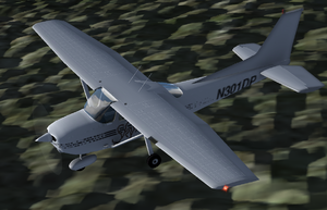
Now load your model and admire the effect:
Final notes
- The normal map uses the same texture coordinates as the original texture. However, the normal map does not need to be the same dimensions, so you can use a smaller or larger normal map if you need to.
- You'll need to define a different Effect for each normal map you use. Effectively this means that if you have two objects using different textures, they will need separate effects.
- The bumpspec.eff effect uses the alpha (transparency) channel on the normal map to set specularity of the point (e.g. shininess). This can be used to make raised parts shiny.
- If you find that the effect is too pronounced, try varying the scaling in the normalmap filter. 0.1 seems to work well for "rivet" effects.
- Make sure all the faces of the object that you assign the effect to have a texture assigned to them, otherwise you will cause a crash in the OpenGL layer (below OSG), because the effect's tangent and binormal vectors are computed using object's texture mapping coordinates. If you try to feed an untextured object to the generator, it should abort with a null vector, and then passing this null vector to the driver leads to a segfault.


