Howto:Build your own procedure trainer
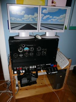
This page is about building your own procedure trainer device using basically FlightGear, other OpenSource software and home brew hardware. It is probably far from being a FNPT Flight Navigation Procedure Trainer , so I'd like to call it a PMPT for Poor Man's Procedure Trainer. The goal is to have most of the components, "real" FNPT have:
- A realistic flight dynamics model
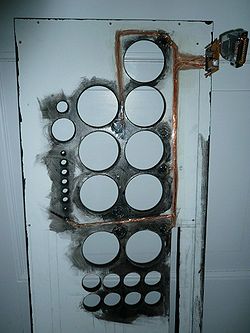
- An instrument panel with realistic looking instruments and controls with realistic behaviour.
- An outside 3d-view rendering the world scenery (but not our own aircraft)
- As many controls as affordable (yoke, rudder, switches, buttons, radios)
- Aircraft is completely flyable without keyboard and/or mouse
The content of this page is growing slowy due to limited spare time. I run this as a low priority task and add something whenever I can spare a timeslice. If you are in desperate need for special information regarding the PMPT, feel free to contact the author by private mail at Torsten@nospam t3r.de. Please ignore the word nospam.
A project containing the sources, schematics and descriptions is archived at:
- Gitorious flightgear-pmpt/cmpt archive
- Gitorious flightgear-pmpt/dme archive
- Gitorious flightgear-pmpt/fg155 archive
- Gitorious flightgear-pmpt/fg archive
- Gitorious flightgear-pmpt/flightgear-pmpt-gitorious-wiki archive
- Gitorious flightgear-pmpt/fsweekend2014 archive
- Gitorious flightgear-pmpt/panel archive
The Components
Bearing the first 'P' of the acronym in mind, most of the hardware is non-state-of-the-art, either from the attic (to bad to be used but to good to be thrown away) or bought second/third hand. The main components are:
- A PC with a 2GHz Athlon, 1.5GB RAM, 100GB HD and a nVidia 7950 graphics card. This is the work horse and the main FlightGear computer.
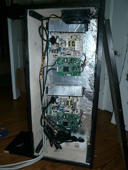
- A second PC, a former diskless "thin client". It has a 1GHz Athlon CPU, 512MB RAM and I replaced the builtin 256MB compact flash memory with a 4GB microdrive from my old iPod mini which was unusable due to its dead battery. The only new item is a nVidia 6xxx graphics card which sits now in the PC's only PCI slot. This PC drives the panel displays.
Update: after the microdrive died, this PC does not have a drive anymore and boots over the network. Even simpler.
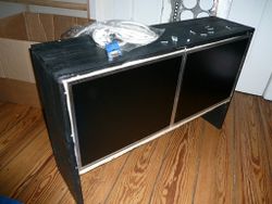
- Two 15" TFT 1280x1024 displays (for a few EURO at ebay) were stripped from their chassis and serve as the panel displays.
- Two 19" TFT 1280x1024 displays (for a few EURO at ebay) sit on top for the outside view.
- A ELITE ProPanel II - this is the most expensive part of the entire PMPT. Also from eBay, came together with the rudder pedals from FlightLink.
- A tiny PC with a touchscreen display, running a Pentium at 600MHz and 256MB RAM is for the moving map application Atlas.
- The homemade USB controller are based on ATMEL microcontroller for less than 10 EURO.
- Ethernet HUP, Cables
Flight Dynamics Model
This is no sweat at all! FlightGear comes with usable, good and even excellent flight dynamics models out of the box. This HOWTO focuses on a Seneca procedure trainer and uses the SenecaII from the FlightGear base package but can be adapted to other aircraft. One computer running a FlightGear instance computes the FDM, renders the scenery and receives all the input from various controls. Hey that's basic FlightGear operation? Yes, read on for the goodies!
Instrument Panel
See also FGPanel
Outside View
Yoke and Switch Panel
Rudder Pedals
Radio Stack
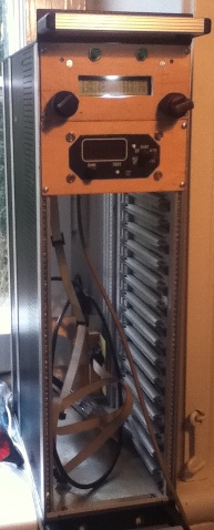
I started building a radio stack from spare parts. An old 19" 3U token-ring hub was emptied from all content and now gives a nice chassis for the "radios". All elements communicate via the I2C TWI interface of the used AVR microcontroller and are bridged with an i2c_tiny_usb I2C/USB interface to the FlightGear computer. Schematics, firmware and userspace programs are at:
- Gitorious flightgear-pmpt/cmpt archive
- Gitorious flightgear-pmpt/dme archive
- Gitorious flightgear-pmpt/fg155 archive
- Gitorious flightgear-pmpt/fg archive
- Gitorious flightgear-pmpt/flightgear-pmpt-gitorious-wiki archive
- Gitorious flightgear-pmpt/fsweekend2014 archive
- Gitorious flightgear-pmpt/panel archive
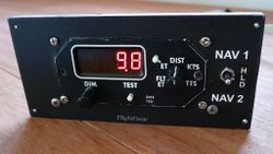
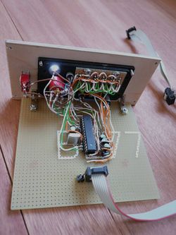
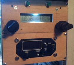
The DME is made from an old real-life DME indicator with all electronics removed. The original PANAPLEX(R) gas discharge display has been removed and replaced by 5 7-segment red LED indicators to avoid a high voltage driver circuit. The two 12V light bulbs for front panel illumination were replaced by two ulra-bright white 5mm LED, so the entire circuit now runs on 5V drawing less than 200mA. The front panel is made of 4mm plywood. The design was printed with a laser printer on a sheet of paper and than glued to the wood.
Using the I2C/SMBus interface, the properties for power, ground-speed and distance are sent from FlightGear to the indicator. The ET and FT timers are computed internally, so is the TTS (time to station). FlightGear reads the position of the source switch to select the active NAV receiver.
More details, source code, schematics and the panel design is at Gitorious flightgear-pmpt/dme archive.
The Basic Hardware Interface
The Almighty USB HID Controller
To make interfacing to FlightGear easy without the need for hardware drivers, a special controller hardware is used. This is based on a commonly available microcontroller, the ATMEL ATMega8-16. It has basically everything needed for I/O handling and most important: it can easily be programmed without the need for a special programmer hardware and a GPL'ed implementation of the USB1.1 protocol stack is available from obdev.at.
Circuit Board
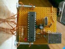
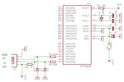
This is the basic circuit diagram for the USB HID controller based on ATMEL's ATMega8. It runs on an 12MHz clock, so be sure to get the 16MHz version. The 27pF capacitors are of ceramic disc type. The 100nF capacitor should be close to the controller with short wires to the supply voltage. The two Z-diodes limit the USB bus voltage and the 1k5Ohm Resistor tells the USB host that this is a low speed device. Check obdev.at's site for details. Their reference projects contains tons of information and further readings. The circuit is so simple, it can easily be built on a prototype board. It leaves us 18 I/O ports, 6 of them may be analog/digital converters. Not bad for a less-than 20$ Hardware.
Firmware
The ATMega8 itself needs a firmware before it is usable for our PMPT and to be recognized as a USB HID device. The source code for the firmware is mostly written in C and can be compiled with the avr-gcc toolchain. To get the resulting binary into the controller, no special programmer hardware is needed as long as you have a computer with a parallel port. Here is a description of the required interface - just two resistors and five wires between your computer and the controller do the trick. Your best friend for programming the ATMega is a dude called avrdude.
