FGPanel

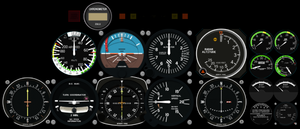
FGPanel is designed as a standalone lightweight panel rendering engine to draw 2D panels on a low-cost computer/graphic card without 3D acceleration at reasonable frame rates.
On Linux, FGpanel comes in two versions - one that runs under X windows, and a version that runs on a system running a console with no windowing system.
A Raspberry Pi Zero is perfectly capable of displaying 15+ instruments on a small monitor when running the non-X console version of FGpanel.
FGPanel was not part of the FlightGear 2.4.0 release for Windows. Windows users can get the executable from Jenkins.
FGPanel on Linux

FGPanel was available as a OpenSUSE Live System, a complete, stand-alone software setup, including OpenSUSE Linux operating system and all necessary start-up scripts. Unfortunately the SuseStudio service was shut down in 2018, so the ISO images are no longer available for download.
FGPanel is still part of OpenSUSE's standard FlightGear packages though. So, to run FGPanel on a separate PC, you can simply install openSUSE and download the FlightGear package from the OpenSUSE repository. See the README for more.
FGPanel on Raspberry Pi
FGPanel has been ported to run on a Raspberry Pi. All what you need is:
- A Raspberry Pi;
- A network to connect the Raspberry Pi with an instance of FlightGear Simulator;
- Raspbian installed on the Raspberry Pi;
- Follow the procedure described in README.RPi to build FGPanel.
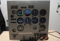
This FGPanel on Raspberry Pi makes it easy and cheap to build a panel for your own procedure trainer.
Configuring FGPanel
Once FGPanel is installed, several configuration files need to be created on both the master FlightGear system and the remote system running FGPanel
2D Panel Configuration File
This is an XML file (for example 2dpanel.xml) that defines the layout of the 2D panel that FGPanel displays. This uses the same syntax as the 2D panel description as described in README.xmlpanel . An example is below for a basic Cessna 172 XML panel running on a Raspberry Pi Zero connected to a 1024x600 screen.
<?xml version="1.0"?>

<!--
Cessna 172 Skyhawk panel for the ATC 610x.
Started by John Check <j4strngs@rockfish.net> - October 2000
Updated by Curt Olson <curt@flightgear.org> - July 2002
_______________________________________________________________________

This is a panel configuration file for the open-source flight
simulator FlightGear (www.flightgear.org).  The file is an XML-encoded
FlightGear property list defining the panel's background texture and
the location (and optionally, size) of the instruments that will
appear on the panel.

Each instrument is, itself, defined in an XML-encoded property list
in a separate file.

Co-ordinates are relative to the *bottom* left corner of the screen
(as in OpenGL).  The total FlightGear window is always considered to
be 1024x768, whatever its actual display size on the screen.  All
paths are relative to $FG_ROOT.

Note that the name of the element defining each instrument must be
different, or else instrument definitions will be overwritten:
that's not particularly XML-ish, but that's how property lists
work in FlightGear right now.

Each instrument has its own preferred width and height, but you can
override those by providing <w>..</w> and <h>..</h> properties with the
<x>...</x> and <y>...</y> properties.
-->

<!DOCTYPE PropertyList SYSTEM "panel.dtd">

<PropertyList>
       <name>Cessna 172P Skyhawk Pi Panel</name>
<!--    <background>Aircraft/c172p/Panels/panel-610x-bg.rgb</background> -->
    <w>1024</w>
    <h>600</h>
    <view-height>5</view-height>

    <instruments>


     <!-- Engine gauge cluster -->

  <instrument include="Aircraft/Instruments/vac-amp-c172s.xml">
            <name>Vacuum Pressure Gauge</name>
            <x>420</x>
            <y>60</y>
            <w>120</w>
            <h>120</h>
        </instrument>

      <instrument include="Aircraft/Instruments/adf-c172s.xml">
            <params>
                <adf-course-rotation-deg>/instrumentation/adf/rotation-deg</adf-course-rotation-deg>
                <adf-needle-deg>/instrumentation/adf/indicated-bearing-deg</adf-needle-deg>
            </params>
            <name>ADF Gauge</name>
            <x>896</x>
            <y>100</y>
            <w>200</w>
            <h>200</h>
        </instrument>
        <!-- End engine gauges cluster -->

        <!-- Engine controls cluster -->
      <instrument include="Aircraft/Instruments/rpm-c172s-digi-hobbs.xml">
            <params>
                <rpm-select>/engines/active-engine/rpm</rpm-select>
            </params>
            <name>RPM Gauge</name>
            <x>60</x>
            <y>60</y>
            <w>120</w>
            <h>120</h>
        </instrument>
        <!-- End engine controls cluster -->

        <!-- Sacred six -->
        <instrument include="Aircraft/Instruments/asi-160-knot-hi.xml">
            <name>Airspeed Indicator</name>
            <x>128</x>
            <y>480</y>
            <w>240</w>
            <h>240</h>
        </instrument>

        <instrument include="Aircraft/Instruments/attitude-indicator-hi.xml">
            <name>Attitude Gyro</name>
            <x>384</x>
            <y>480</y>
            <w>240</w>
            <h>240</h>
        </instrument>
<!--        <instrument include="Aircraft/Instruments/altimeter.xml"> -->
         <instrument include="Aircraft/Instruments/alt-c172s.xml">
            <name>Altimeter</name>
            <x>640</x>
            <y>480</y>
            <w>240</w>
            <h>240</h>
        </instrument>
        <instrument include="Aircraft/Instruments/trn-c172s.xml">
            <name>Turn Coordinator</name>
            <x>128</x>
            <y>240</y>
            <w>240</w>
            <h>240</h>
        </instrument>
        <instrument include="Aircraft/Instruments/hdg-c172s.xml"> -->
        <!--  <name>Directional Gyro</name> -->
            <params>
                <heading-deg>/instrumentation/heading-indicator/indicated-heading-deg</heading-deg>
            </params>
            <name>Bendix King HSI</name>
            <x>384</x>
            <y>240</y>
            <w>240</w>
            <h>240</h>
        </instrument>
        <instrument include="Aircraft/Instruments/vsi-c172s.xml">
            <name>Vertical Speed Indicator</name>
            <x>640</x>
            <y>240</y>
            <w>240</w>
            <h>240</h>
        </instrument>
        <!-- End sacred six -->

        <!-- Radio nav instruments -->
               <instrument include="Aircraft/Instruments/vor1-c172s.xml">
            <name>VOR 1 Gauge</name>
            <params>
                <nav-to-flag>/instrumentation/nav[0]/to-flag</nav-to-flag>
                <nav-from-flag>/instrumentation/nav[0]/from-flag</nav-from-flag>
                <nav-radial-selected>/instrumentation/nav[0]/radials/selected-deg</nav-radial-selected>
                <nav-gs-needle-deflection>/instrumentation/nav[0]/gs-needle-deflection</nav-gs-needle-deflection>
                <nav-heading-needle-deflection>/instrumentation/nav[0]/heading-needle-deflection</nav-heading-needle-deflection>
                <nav-has-gs-needle>/sim/instrument-options/nav[0]/has-gs-needle</nav-has-gs-needle>
                <nav-needles-pivot>/sim/instrument-options/nav[0]/needles-pivot</nav-needles-pivot>
            </params>
            <x>896</x>
            <y>500</y>
            <w>200</w>
            <h>200</h>
        </instrument>
       <instrument include="Aircraft/Instruments/vor1-c172s.xml">
            <name>VOR 2 Gauge</name>
            <params>
                <nav-to-flag>/instrumentation/nav[1]/to-flag</nav-to-flag>
                <nav-from-flag>/instrumentation/nav[1]/from-flag</nav-from-flag>
                <nav-radial-selected>/instrumentation/nav[1]/radials/selected-deg</nav-radial-selected>
                <nav-gs-needle-deflection>/instrumentation/nav[1]/gs-needle-deflection</nav-gs-needle-deflection>
                <nav-heading-needle-deflection>/instrumentation/nav[1]/heading-needle-deflection</nav-heading-needle-deflection>
                <nav-has-gs-needle>/sim/instrument-options/nav[1]/has-gs-needle</nav-has-gs-needle>
                <nav-needles-pivot>/sim/instrument-options/nav[1]/needles-pivot</nav-needles-pivot>
            </params>
            <x>896</x>
            <y>300</y>
            <w>200</w>
            <h>200</h>
        </instrument>
        <!-- End radio nav instruments -->


     <instrument include="Aircraft/Instruments/egt-ff-c172s.xml">
            <name>Exhaust Gas Temperature Gauge</name>
            <x>180</x>
            <y>60</y>
            <w>120</w>
            <h>120</h>
        </instrument>

     <!-- Engine gauge cluster -->
      <instrument include="Aircraft/Instruments/fuel-c172p.xml">
            <name>Fuel Gauge</name>
            <x>360</x>
            <y>60</y>
            <w>600</w>
            <h>600</h>
        </instrument>

     <!-- Engine gauge cluster -->
      <instrument include="Aircraft/Instruments/oil-c172p.xml">
            <name>Oil Gauge</name>
            <x>660</x>
            <y>60</y>
            <w>600</w>
            <h>600</h>
        </instrument>


    </instruments>

</PropertyList>
Each <instrument>...</instrument> block describes an instrument, referencing the instrument descriptions in $FGDATA/Aircraft/Instruments.
The key parameters for each instrument are as follows:
- The
<instrument>...</instrument>line is the instrument to display with path to the instrument description relative to$FGDATA - The
<name>...</name>is a description of the instrument - this can be anything as it's not used for display - The
<x>and<y>are the position of the centre of the instrument on screen in pixels, referenced to the top left of the screen. - The
<w>and<h>are the width and height of the instrument in pixels. Refer to the<instrument>.xmlin$FGDATA/Aircraft/Instrumentsfor the default shape and size of each instrument
If you look at the individual XML files that define the instrument, these have the properties in the property tree that need to be sent. Some instruments have a <params> block - this allows you to alias parameters being sent from the property tree (as described below) to the properties displayed by the instruments - this is particularly useful for duplicated instruments such as navigation displays. Refer to README.xmlpanel for more details. Make a note of which values from the property tree each instrument requires, and any aliases as you will need it in the next step.
Parameter File
The next file you need is an XML file (panel_send.xml) that tells FlightGear which values from the property tree to send to the panel. This needs to be present on both the computer running FlightGear and the panel computer. Both versions need to be identical. An example for the above 2dpanel.xml is below:
<?xml version="1.0"?>

<PropertyList>
 <generic>

  <output>
   <line_separator>newline</line_separator>
   <var_separator>,</var_separator>

        <chunk>
            <name>Altitude</name>
            <node>/instrumentation/altimeter/indicated-altitude-ft</node>
            <type>integer</type>
            <format>%i</format>
        </chunk>

        <chunk>
            <name>Airspeed</name>
            <node>/instrumentation/airspeed-indicator/indicated-speed-kt</node>
    <type>float</type>
    <format>%.1e</format>
        </chunk>

        <chunk>
            <name>VSI</name>
            <node>/instrumentation/vertical-speed-indicator/indicated-speed-fpm</node>
            <type>integer</type>
            <format>%i</format>
        </chunk>

   <chunk>
    <type>float</type>
    <format>%.2e</format>
    <node>/position/altitude-agl-ft</node>
   </chunk>

   <chunk>
    <type>float</type>
    <format>%.2e</format>
    <node>/instrumentation/attitude-indicator/indicated-roll-deg</node>
   </chunk>

   <chunk>
    <type>float</type>
    <format>%.2e</format>
    <node>/instrumentation/attitude-indicator/indicated-pitch-deg</node>
   </chunk>

   <chunk>
    <type>float</type>
    <format>%.2e</format>
    <node>/instrumentation/attitude-indicator/horizon-offset-deg</node>
   </chunk>

   <chunk>
    <type>float</type>
    <format>%.4e</format>
    <node>/instrumentation/attitude-indicator/spin</node>
   </chunk>

   <chunk>
    <type>float</type>
    <format>%.4e</format>
    <node>/instrumentation/slip-skid-ball/indicated-slip-skid</node>
   </chunk>

   <chunk>
    <type>float</type>
    <format>%.4e</format>
    <node>/systems/electrical/outputs/turn-coordinator</node>
   </chunk>

   <chunk>
    <type>float</type>
    <format>%.4e</format>
    <node>/instrumentation/turn-indicator/indicated-turn-rate</node>
   </chunk>

      <chunk>
    <type>integer</type>
    <format>%i</format>
    <node>/consumables/fuel/tank[0]/level-gal_us</node>
   </chunk>

   <chunk>
    <type>integer</type>
    <format>%i</format>
    <node>/consumables/fuel/tank[1]/level-gal_us</node>
   </chunk>

          <chunk>
    <type>integer</type>
    <format>%i</format>
    <node>/engines/active-engine/indicated-oil-final-temperature-degf</node>
   </chunk>

   <chunk>
    <type>float</type>
    <format>%.4e</format>
    <node>/engines/active-engine/indicated-oil-pressure-psi</node>
   </chunk>


            <chunk>
    <type>float</type>
    <format>%.4e</format>
    <node>/systems/vacuum/suction-inhg</node>
   </chunk>

   <chunk>
    <type>integer</type>
    <format>%i</format>
    <node>/instrumentation/adf/rotation-deg</node>
   </chunk>

      <chunk>
    <type>integer</type>
    <format>%i</format>
    <node>/instrumentation/adf/indicated-bearing-deg</node>
   </chunk>

          <chunk>
    <type>integer</type>
    <format>%i</format>
    <node>/engines/active-engine/rpm</node>
   </chunk>

              <chunk>
    <type>integer</type>
    <format>%i</format>
    <node>/instrumentation/nav[0]/to-flag</node>
   </chunk>

                  <chunk>
    <type>integer</type>
    <format>%i</format>
    <node>/instrumentation/nav[0]/from-flag</node>
   </chunk>

                   <chunk>
    <type>integer</type>
    <format>%i</format>
    <node>/instrumentation/nav[0]/radials/selected-deg</node>
   </chunk>

                     <chunk>
    <type>float</type>
    <format>%.4e</format>
    <node>/instrumentation/nav[0]/gs-needle-deflection</node>
   </chunk>

                       <chunk>
    <type>float</type>
    <format>%.4e</format>
    <node>/instrumentation/nav[0]/heading-needle-deflection</node>
   </chunk>

                        <chunk>
    <type>integer</type>
    <format>%i</format>
    <node>/sim/instrument-options/nav[0]/has-gs-needle</node>
   </chunk>

                          <chunk>
    <type>float</type>
    <format>%.4e</format>
    <node>/sim/instrument-options/nav[0]/needles-pivot</node>
   </chunk>

                <chunk>
    <type>integer</type>
    <format>%i</format>
    <node>/instrumentation/nav[1]/to-flag</node>
   </chunk>

                  <chunk>
    <type>integer</type>
    <format>%i</format>
    <node>/instrumentation/nav[1]/from-flag</node>
   </chunk>

                   <chunk>
    <type>integer</type>
    <format>%i</format>
    <node>/instrumentation/nav[1]/radials/selected-deg</node>
   </chunk>

                     <chunk>
    <type>float</type>
    <format>%.4e</format>
    <node>/instrumentation/nav[1]/gs-needle-deflection</node>
   </chunk>

                       <chunk>
    <type>float</type>
    <format>%.4e</format>
    <node>/instrumentation/nav[1]/heading-needle-deflection</node>
   </chunk>

                        <chunk>
    <type>integer</type>
    <format>%i</format>
    <node>/sim/instrument-options/nav[1]/has-gs-needle</node>
   </chunk>

                          <chunk>
    <type>float</type>
    <format>%.4e</format>
    <node>/sim/instrument-options/nav[1]/needles-pivot</node>
   </chunk>

                             <chunk>
    <type>float</type>
    <format>%.4e</format>
    <node>/instrumentation/heading-indicator/indicated-heading-deg</node>
   </chunk>

                             <chunk>
    <type>integer</type>
    <format>%i</format>
    <node>/autopilot/settings/heading-bug-deg</node>
   </chunk>

                 <chunk>
    <type>float</type>
    <format>%.4e</format>
    <node>/instrumentation/altimeter/setting-inhg</node>
   </chunk>

                <chunk>
                <type>integer</type>
    <format>%i</format>
        <node>/consumables/fuel/tank[0]/level-gal_us</node>
           </chunk>

                 <chunk>
    <type>integer</type>
    <format>%i</format>
        <node>/consumables/fuel/tank[1]/level-gal_us</node>
           </chunk>

                   <chunk>
    <type>integer</type>
    <format>%i</format>
        <node>/engines/active-engine/egt-degf</node>
           </chunk>

                    <chunk>
    <type>integer</type>
    <format>%i</format>
        <node>/systems/electrical/volts</node>
           </chunk>

                     <chunk>
    <type>integer</type>
    <format>%i</format>
        <node>/systems/electrical/amps</node>
           </chunk>

  </output>
 </generic>
</PropertyList>
Each <chunk> section defines which property is sent. These need to be the same as defined in the instrument definition in $FGDATA/Aircraft/Instruments/<instrument>.xml, or as referred to by the assigned alias to the parameter. A tip here - make sure that any value that needs decimals (for example radio frequencies) are sent as a floating point numbers with sufficient decimal places defined.
FGpanel launch file
The next file you need is an XML on the receiving (panel) computer (panel_launch.xml) that configures FGpanel. An example for the above files is below:
<PropertyList>

  <!-- true: run full-screen, false; run in window -->
  <game-mode type="bool">false</game-mode>

  <!-- include the panel definitions (2d-panel syntax)-->
  <panel include="2dpanel.xml"/>

  <!-- compose your property-tree here -->
  <sim>
    <panel>
      <flip-x type="bool">false</flip-x>
    </panel>
    <instrument-options>
      <omit-knobs type="bool">true</omit-knobs>
    </instrument-options>
  </sim>

  <!-- network communication settings -->
  <communication>
    <listen>
      <!-- interface to bind to,
           leave empty for all interfaces -->
     <host></host>   <!-- multicast address! -->
<!--     <host>fg_computer_ip</host> -->  <!-- multicast address! -->
      <port>5432</port> <!-- tcp port to listen to -->
      <style>udp</style> <!-- udp or tcp (forget about tcp!) -->
    </listen>

    <!-- the generic protocol definition

    -->
    <protocol include="panel_send.xml"/>
  </communication>
</PropertyList>
The key lines in this are:
<panel include="/path/to/2dpanel.xml"/>- (line 7). This is the path to and name of the panel layout definition file (2dpanel.xmlin this example) on the panel computer.<host>- (line 24 and 25) the IP address of the computer running FlightGear that the panel computer listens for. if you leave this blank it will listen for data from all hosts on the subnet.<port>- (line 26) the port that the panel computer listens for data on - this has to be specified.5432is the default.<style>- (line 27) the protocol to listen. this should be set to UDP<protocol-include="/path/to/panel_send.xml"/>- (line 33) this is path to and name of the file that defines the parameters being sent from the main computer. This needs to be the path to and name of the copy of the file on the panel computer
One further requirement: $FGDATA on the panel computer
Additionally, the panel computer needs a copy of the $FGDATA directory, including all instrument definitions. A full FlightGear install is recommended as FGPanel has some dependencies to the full FlightGear installation.
Launching FGpanel
Once configuration is complete, FGpanel can be launched on the panel computer:
/path/to/fgpanel --fg-root=/path/to/fg/data --panel=/path/to/2dpanel.xmlWhere --fg-root is the location of the FlightGear data directory on the panel computer, and --panel is the path to and name of the 2dpanel.xml definition
On a raspberry pi, fgpanel in the above command may need to be substituted for fgpanel-egl
Console messages may be visible through the instruments - these can be suppressed by appending '&> /dev/null' to the end of the above command.
Launching FlightGear
FlightGear can now be launched on the main computer as usual. However one option needs to be added to the launcher (either in the GUI or the command line) so that the required properties are sent to the panel computer:
--generic=socket,out,refresh_rate,panel_computer_ip,port,udp,"/path/to/panel_send.xml"In the above:
refresh_rate- this is the refresh rate (in Hz) to send the property tree values. 25 should be sufficientpanel_computer_ip- the IP address of the computer running FGpanelport- the port to send data on, must be the same as defined inpanel_launch.xml(5432 in the above examples)/path/to/panel_send.xml- the path to and name of thepanel_send.xmlfile on the FlightGear computer
The panel should now replicate the instruments displayed on the main FlightGear computer.
Related content
- Howto: Build your own procedure trainer, describes how you can create a "cheap" procedure trainer, making use of FGPanel to draw the instruments.
Readme files
As FGPanel use stripped down for the 2D panels these readme files can also be useful
- $FG_ROOT/Docs/README.xmlpanel
- $FG_ROOT/Docs/README.xmlpanel.html