McDonnell Douglas F-15 Eagle
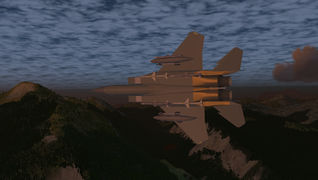
 External view | |
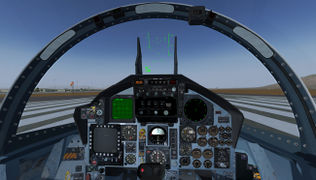
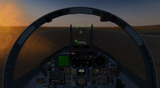
 Cockpit view | |
| Type | All-weather tactical fighter, Fighter aircraft, Interceptor aircraft |
| Propulsion | Twinjet (Jet aircraft, Twin-engine aircraft) |
| Manufacturer | McDonnell Douglas, Boeing |
| Author(s) |
|
| FDM | JSBSim |
| --aircraft= |
f15c f15d f15dbs |
| Status | Advanced production |
| FDM |
|
| Systems |
|
| Cockpit |
|
| Model |
|
| Supports |
|
| Development | |
| Website |
|
| Repository |
|
| Download |
|
| License | GPLv2+ |
|
| |
The McDonnell Douglas (now Boeing) F-15 Eagle is an American twin-engine, all-weather tactical fighter designed by McDonnell Douglas to gain and maintain air superiority in aerial combat. Following reviews of proposals, the United States Air Force selected McDonnell Douglas' design in 1967 to meet the service's need for a dedicated air superiority fighter. The Eagle first flew in July 1972, and entered service in 1976.
The Eagle boasts an all-service kill ratio of 104:0. The F-15 downed the majority of Iraqi aircraft in the Gulf War of 1991, and the same in the Balkan conflict of 1999.
The F-15 was originally envisioned as a pure air superiority aircraft. Its design included a secondary ground-attack capability that was largely unused in the C and D variants. For this reason only air to air missiles are currently supported.
The design proved flexible enough that an all-weather strike derivative, the F-15E Strike Eagle, was later developed, entering service in 1989. The F-15 Eagle is expected to be in service with the U.S. Air Force past 2025. The F-15 production line was initially set to end in 2019, 47 years after the type's first flight.
The variants of the F-15 modeled in FlightGear are the F-15C (single-seater) and the F-15D (two-seater training variant).
Features
- F-15C and D variants
- Realistic FDM based on windtunnel-derived aerodynamic data found in (AFIT/GAE/ENY/90D-16). [1]
- Photorealistic 3D cockpit with real cockpit textures provided by Gene Buckle from his unique F-15C Eagle Flight Simulator Project.
- Operational weapons and radar.
- Full range of sound simulation (buffet, gear, engines, etc.). Cockpit aural warnings including voice.
- Canvas radar and HUD, VSD, TEWS, and MPCD.
- Refuelling and stores.
- In-cockpit engine start (including JFS).
- Modelled hydraulic and electrical systems.
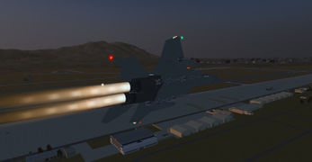
- ALS afterburner flames. These flames are Rembrandt-compatible and adjust to take into account ambient lighting.
- External and internal Rembrandt-compatible lighting.
- Modelled ECS, including pressurisation, windscreen temperature, and frosting.
- Control actuator system.
- Overload Warning System.
- Caution/warning system.
Simulation Fidelity and limitations
- The windtunnel data is valid for a clean configuration at Mach 0.6. The aerodynamic model has been adapted to the entire range of the aircraft, Mach 0 to Mach 2.5.
- Forces and moments for flaps, gear, stores, have been added based on parameter estimation and by using data from other reports. These been validated by comparison with plots from various reports and results are within a tolerance that is acceptable for a desktop simulation.
- ECS, HYDS and Electrics systems models are simplified and do not accurately follow the schematics for the aircraft.
- Timings for gear, cockpit opening are based on observation of video evidence.
- The MPCD is restricted to only implement a few pages, notable PACS
- I have not attempted to accurately model in any way the TEWS system, as all details on it are restricted by security classification.
- Missile dynamics and tracking simulation is simplistic (based on the work by xiii, and Shinobi), AIM-9 is most accurate, with AIM-7 and AIM-120 being not quite so realistic
- Flight controls and the CAS system are reasonably well modelled; but again accurate data isn't readily available so this is based largely on a published article and knowledge gained from technical reports.
Gallery
| There is a category with screenshots of the McDonnell Douglas F-15 Eagle. |
F 15C Cockpit Nellis AFB
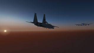
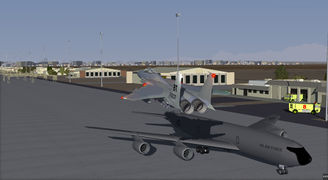
F 15C approaching refueling tanker

F 15C circling Nellis AFB

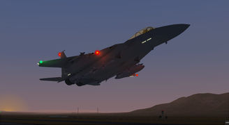
F 15C dawn afterburner departure
F 15C dawn afterburner flypast Nellis AFB
F 15C dawn afterburner flypast
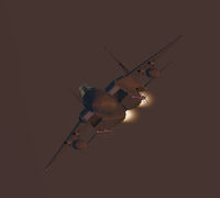
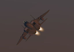
F 15C dawn afterburner incoming
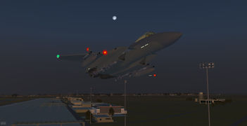
F 15C dawn flypast
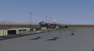
F 15C dawn leaving Nellis AFB
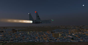
F 15C dawn single engine flameout afterburner departure
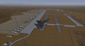
F 15C departure Nellis AFB
F 15C flypast Nellis AFB FireDepartment
F 15C flypast Nellis AFB

F 15C leaving Sion
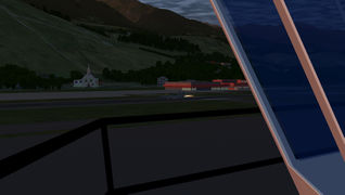
F 15C leaving view from tower Sion
F 15C underside over Sion
F-15C on the runway at KSFO
F 15D at cruise


Flight Controls
ARI
The ARI is a system that automatically applies rudder based on aileron movement (designed to work as an aid as it's what a good pilot should do anyway). The schedule adjusts based on configuration and airspeed. The system is disabled above Mach 0.9 or whenever the landing gear is deployed.
CAS
The CAS system is a three channel system (Yaw, Pitch, Roll). The YAW channel is basically a yaw damper, the pitch channel is basically a pitch damper and the roll channel is a roll rate limiter. It is not recommended to fly with the YAW CAS channel disabled and is liable to result in serious yaw oscillation at higher mach. If any of these systems are disabled (or inoperative) a warning light will be visible on the caution / warning panel.
Pitch Ratio and Roll Ratio
The CADC adjusts the amount of surface movement of the elevator, ailerons and differential elevator per inch of stick movement based on the airspeed to improve the controllability at higher speeds. Both of these systems can be turned off at the roll ratio is on the MISC panel on the left console, the pitch ratio switch is on the centre panel next to the landing gauge. There is also a gauge on this panel which indicates the current pitch ratio either 0.5 in the emergency mode or the value determined by the CADC .
Aural Warnings (v1.2f)
The following audio warnings are given;
- AOA > 25 (900hz beep beep pause)
- AOA > 30 and gear down (1600hz beeping)
- 85% to 91% of maximum G loading reached (900hz 4 times per second)
- 92% to 95% of maximum G loading (900hz 10 times per second)
- 96% to 100% of maximum G loading (continuous 900hz tone)
- Gear not down when below 200 kts. (900hz beeping)
- Voice warnings for:
- Whenever the Master Caution light illuminates (CAUTION)
- Bingo Fuel
- More than 100% of maximum G loading (OVER-G)
The OWS calculates the maximum permissible G loading based upon the current configuration.
Cockpit
Main centre panel

Warning lamps

Primary Instruments
Altimeter

Acceleration (G)

Angle of Attack

Airspeed Indicator

Fire Panel
Fire suppression panel. There is no simulation of the fire suppression system. The only functional parts of this panel are the burn thru lights that indicate that the temperature of the area surrounding the engines is too high. If these light the correct procedure is to reduce augmentation and engine power until the temperature returns to an acceptable range.

Flaps Panel
The flaps panel contains the hook control for the emergency hook. This is intended for use in wire arrested emergency airfield landings and is not strong enough for carrier landings; however in this model these limits are not simulated so it is possible to land the aircraft on a carrier.
There is an indicator for the status of the flaps. The top light will indicate in amber when the flaps are in transit, and the green light below is when the flaps are locked in the open position.

Landing Gear Panel
The landing gear panel contains a handle that controls the position of the landing gear. Landing gear can be deployed or retracted by clicking on the handle (or by using g/G). When the gear is in transit a red lamp will illuminate the handle. When on the ground the handle will move but the gear will not.
There is a landing gear warning horn that will sound when below 200kts and descending; this can be silenced by pushing the silence button.

Pitch Ratio Panel
Next to the landing gear is the pitch ratio panel. The primary flight control effectivity is adjusted following a schedule to produce about the same acceleration (G) per inch of stick movement. The gauge indicates the current ratio, and the emergency pitch ratio switch will lock this at 0.5 in the event of system failure. When the landing gear is down the pitch ratio is locked at 1.0
Emerg Jett Panel
The Emerg Jett button will, when fully depressed, jettison all armaments and fuel tanks.
The Emergency Jettison panel also contains a selector for the Steer Mode which is primarily used to control the flight director bars on the ADI.

Lower centre panel
This contains the Attitude Director Indicator, Horizontal Situation Indicator, jettison and arm modes controls.

Standy Instruments
There are standby instruments for the following.
- ADI
- Airspeed
- Altitude
These will operate when no electrical power is available or in the event of Avionics failure.
The lighting for these is controlled by the switch "STBY INST" on the lighting panel.

Vertical Velocity Indicator (VVI)

Cabin Pressure and JFS
Providing that the ECS is receiving sufficient bleed air the cabin pressure will be maintained according to the correct schedule.
To start JFS first use the Engines Master Panel in the right hand console to switch the JFS on and then pull the lever. Providing that there is sufficient hydraulic pressure in the Util system JFS will start. If there is insufficient pressure you must use the Quickstart button from the menu as there is no way to recharge this system without engines or external electrical power.

Canopy warning panel
The canopy warning panel contains warnings for when the canopy is unlatched. The other warning lights on this panel will not illuminate as these systems are not simulated.

ARM Modes Panel
This selects the primary arm mode. For normal air to air operation all modes need to be off. Other mode operations are not simulated in this model.

Caution Warning Panel
This panel contains warning lights that indicate problems with the aircraft.
The Emergency Vent lever will rapidly depressurize the cabin in case of emergency.

Main panel / Engines
The right hand side of the main panel contains the engines gauges, together with the hydraulics and fuel gauges.
The drums on the EGT gauges will have the red digits for the first two digits when EGT is dangerously high.
The UTIL hyd system needs to be over 1200 psi to perform a JFS start.
The pressures displayed will normally be 2900-3100, however these values may differ when an engine has flamed out, or when the emergency (electrical) hydraulic backup is running in the case of primary pump failure. When the hydraulic pressure drops below 1000 the primary surfaces, gear and flaps will not move. This only usually happens when fuel runs out and N1 drops below 20%.
The selector on the fuel gauge selects the tanks displayed in the lower two drum displays. This selector also has a test position that is spring loaded. To ensure that the gauge is operating correctly select this position and the displays will show 6000.

Left Console

The throttles move roughly half way for military power, and the remaining area is for the five stage thrust augmentation (Burners).
The lower switch on the throttle controls the selected armament type, and cycles between GUN,SRM (Short Range Missiles AIM-9),MRM (Medium Range Missiles AIM-7, AIM-120)

Right Console

HUD
The F-15 HUD is a multi-function device that will display different information depending on the primary mode as determined by the avionics. Prior to the E variant the HUD used an optical combiner with two panes of glass angled such that at the correct eyepoint these appear as a single device. This is accurately simulated, so when viewing off angle the two panes will be visible.
When Master ARM is on the currently selected weapon type is displayed with the currently selected targetting information on the right. Targets are displayed on the HUD as a box. The currently selected target is a double box.
When AOA is greater than 20 degrees, or when the gear is down the AOA is displayed, otherwise the Mach number is displayed.
The current vertical G loading is displayed on the bottom left, with the current maximum permitted G loading displayed next to this. If the Overload Warning System is inoperative "NOWS" will be displayed in place of the maximum loading.
The route manager is integrated into the autopilot and when a route is being followed the route manager the routing information will be displayed on the right.
HUD Controls
At the top is the IFF / Transponder code.
Underneath is the radio 1 comms frequency and mode.
At the bottom there are the brightness and symbology controls.

MPCD
To get to the PACS page; select armament, then A/A
MPCD Armament

MPCD PACS
PACS Display
To get to the PACS page; select armament, then A/A. To return to the top menu use the R4 button "M"
The currently selected missile will be surround by a white box. When master arm is one the label field will change to "RDY" and be displayed in green.
The GUN Rounds remaining are indicated next to the L2 Menu button

TEWS
The TEWS system is a crucial integrated part of the F-15 defensive systems and operation and specification is classified. For this model the TEWS will display identified targets, with their callsign and orientation based on the currently selected radar range.

VSD
The VSD displays target information together with the roll and pitch of the aircraft. The currently selected target is displayed in a higher intensity / bold.
Target range, type, callsign, closure rate and altitude are displayed for the currently selected target.

Lighting
Exterior lighting is controlled on the left console EXTERIOR LTS panel.
Taxi / landing light is selected on the MISC panel at the front left of the left console.

Interior lighting is controlled on the right console LIGHTING PANEL
Armaments
The F-15 can carry the following missile types:
- AIM-7
- AIM-120
- AIM-9
Loading of these is controlled by the Fuel and Payload dialog, or by using the External Stores dialog on the F-15 menu.
External Fuel tanks need to be selected on the fuel and payload dialog. Normally the F-15 will carry external fuel on the wings, in rare circumstances (e.g. ferry configuration) the centre external tank will be used.
Selection of the armament type is via the control on the throttle (or use the w key). As this selects the type the AIM-7 or AIM-120 will be selected based on rules within the armaments system.
Forward Canopy Top
On the forward canopy top there are lights for LOCK/SHOOT when the missile has a good lock on the target, a READY light that indicates that the Air To Air Refuelling system is operation and a standby compass.
The mirrors on the canopy do not show any reflections (not currently possible within FGFS).

Air to Air refueling operations
To perform air to air refueling the F-15 is fitted with a boom receptacle behind a door on the left side of the aircraft. This door needs to be open before fuel can be taken from a tanker. When the refueling system is ready this is indicated on the top left of the canopy bow with the green "READY" lamp.
Fuel Dump
The fuel dump will operate when the switch is selected at a predefined rate from the tanks.
Backseat operations

The f15dbs aircraft (F-15D multiplayer) allows you to ride along. Currently aircraft control from the backseat is not possible, so you're just along for the ride.
External Links
| References |
| |||||||||||
| |||||||||||