PHI - Position and Homing Indicator
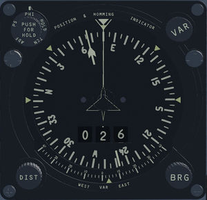
When you look at the cockpit of the FIAT G91 (but also of the F104) you can see in the center at the top a very particular instrument, particularly large and with four knobs on the sides. That instrument was one of the first navigation systems that used Doppler radar to determine ground speed.
The accuracy of the instrument was, for those times, rather high, as it allowed to travel a long route up to 999 miles with a deviation in the position of the aircraft of 2-3%, a contained error that could be exploited both for flights both military and civilian in the transatlantic route, and in tactical flight in enemy territory or in areas with little radio assistance coverage. However, the real disadvantage in military use was that the instrument allowed to achieve this accuracy only with the use of the doppler radar, in the event that the pilot had disengaged the radar device, in order to be less visible to the enemy, the accuracy decreased a lot and was linked to the real knowledge of the local weather situation.
Technique
On the lower part of the plane there were 4 antennas with radial beams facing the ground. During the flight the return signals of the two front beams, compared to the two rear beams had a different frequency, this difference was proportional to the speed of the aircraft on the ground. With this speed difference technique, it was possible to establish the speed with high accuracy. The accuracy, however, decreased in the case of mountainous terrain or in turns. Therefore it was necessary to have two groups of beams to average the values and thus obtain a less error-prone result.
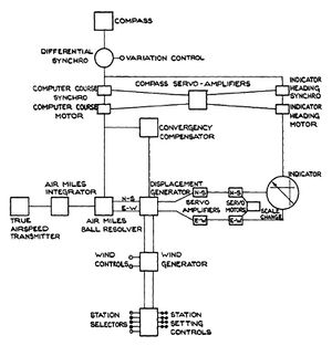
It is important to remember that the technique was possible with the constant improvement of the quality of radars and their simultaneous miniaturization due to the rapid development of this device during and after the Second World War. The PHI model used in the FIAT G91 and in the F104s from the A-B to G series and in various civil aircraft including the DC8, was mechanical (ball integrator) and with tube electronics, no transistors were still used.
This fact made the instrument rather bulky for a small and compact aircraft like the G91 and therefore its use considerably reduced the space in the forward avionics compartment where the processing unit was located.
The reliability was good, certainly superior to that of the radars of the time, but it certainly could represent a problem for long flights in sparsely inhabited areas without radio aids to navigation.
The apparatus required a lot of power, about 150W, partly with 28V voltage and partly with 400 Hz alternating at 115V needed to drive the various synchronous motors and related actuators.
The main documentation found on the net that technically describes the operation of the device is that of the PDF file: AD091920 aut. RL JEFFERIES year 1955 [1]. This device performance evaluation document gives a clear idea of how it was designed and the parts that make it up. Its reading is really useful and has allowed us to create a sufficiently real model for an instrument that has not been operational for at least 20 years.
Programming the routes
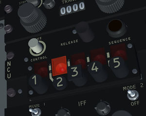
Programming The instrument allows you to sequentially follow up to five routes stored in the Station Selector (unit with the code NCU located to the right of the pilot). A route consists of two values: N-S and E-W coordinates measured in air miles of the next point [1]. The NCU allowed the insertion of a box containing four multiturn resistors (10 turns) to enter the distance N-S and other four multiturn resistors to enter the distance E-W. Once the route was planned, the navigator made a list of max. 5 pairs of coordinates, the first pair was not inserted into the device, but only communicated to the pilot, who set it on the display, the other four pairs were set by a technician using a special programming device and a screwdriver that turned the potentiometers placed on the programming box. The cassette could be inserted into the compartment with a light pressure and extracted using the release button [2] dell NCU unit.
Programming The instrument allows sequentially follow up to 5 routes stored in the Station Selector (unit with the code NCU located to the right of the pilot). A route consists of two values: N-S and E-W coordinates measured in air miles of the next point [1].
In the simulation, as will see later, the two coordinates have been replaced by a distance and an angle (heading), with respect to the geographic North. In this way it is possible to quickly integrate the polar coordinate programming method of the routes obtained from the route manager of the FGFS program with the N-S and E-W system used by the PHI.
Parts constituting the apparatus
Within various spaces within the aircraft:
- 4-beam doppler transmitter and relative antenna positioned on the underside of the aircraft.
- Computer unit.
- Signal amplifier and Junction-Box.
- Pitot tube to obtain the static and dynamic pressure without interfering with that used by the pneumatic instruments on board.
- Gyro Compass with fluxgate magnetic sensor.
Inside the pilot's cabin:
- Indicator Unit normally placed in front of the pilot at the top of the cockpit.
- Wind control unit, a device necessary to enter the wind speed and direction in order to automatically calculate the deviation due to the wind.
- Selector unit, keypad necessary to activate the device, together with a switch / programmer of the (1 + 4) possible routes.
- Doppler radar management unit.
Guide to using the PHI system
The user guide is based on the PHI device included in the FIAT G91R1B project. There are no particular differences in the case that it is used in other airplanes made in the period of the years from 1955 to 1970.
Flight planning
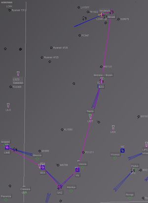
Flight departure from Innsbruck airport (LOWI rwy: 08) and arrival to Bergamo Orio (LIME rwy: 30) airport.
Flightgear's route manager is a good way to plan your route using the map to extract references and see the actual planned route.
Looking at the Route Manager table, it can be seen that there is always an angle (ODO) with respect to north and the length of the section to be covered. The last stretch is the one in sight of the airport and must be managed differently with the classic methods of instrumental or visual navigation.
Looking at the Route Manager (RM) table, it can be seen that there is always an angle (ODO) with respect to the north and the length of the section to be covered. The last stretch is the one in sight of the airport and must be managed differently with the classic methods of instrumental or visual navigation.
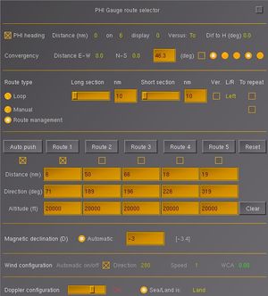
To load the data into the PHI table (in fact it is as if you were programming the "Selector Unit Programmer" (NCU) portable cassette, just click on the [Activate] button of the RM. you go now on the menu [Fiat G91] followed by [PHI - route system] opens a window showing various parameters among which we highlight five columns that correspond to the five 'buttons NCU, these columns have been filled in by the distance to cover, the direction and finally the altitude of the flight obtained by the Route Manager (if the altitude is zero in the RM this is set to 15,000 ft).
The PHI programming framework also contains other parameters among which we have the convergence [3]
Below we have a section that defines the way we want to generate the route:
- Loop: it is a demonstrative or useful programming to make a waiting circuit, the two courses allow you to define the length of the two sides, the direction of rotation which can be right or left and the "To repeat" parameter sets to the PHI to start over when a loop has been completed.
- Manual: the table is inserted manually.
- Route manager: the data has been loaded from RM.
In reality the five columns corresponded to the programming of only four columns, the first was set manually by the pilot.
The [Auto push] button allows to obtain the automatic progression of the route, in reality it was manual, obviously you can decide the progression manually.
The next block is the insertion of the magnetic declination, also in this case it is automatic, at least that the pilot does not want to do it himself.
The Wind configuration is used to automatically enter the wind direction and speed, otherwise it must be entered manually with the appropriate PHI system gauge.
Finally there is the section dopplerwhich defines four possible ways of use:
- OFF
- Rec only (keeping the doppler warm, but without signal emission, useful in the enemy area)[4]
- ON (Operative)
- Test
The selector sea / land allows you to adjust a filter that improves the Doppler's operability when you have to cross a stretch of sea.
References
|
