Avionics and instruments
Compass
The compass aligns itself along the magnetic field that surrounds the earth. As such, it is subject to various influences that affects the direction in which it points.
Magnetic variation
Note that The magnetic north pole and the geographic north pole are not located at the same spot. The difference between the magnetic field and true north is called "magnetic variation" or "magnetic declination". The magnetic variation is expressed as an angle east or west of true north. Not only does the magnetic variation vary with position on the planet, it also slowly varies over time since the magnetic poles are not stationary.
When planning a flight it is necessary to know the magnetic variation along the flight path. Air navigation is generally done using magnetic bearings, and the VOR beacons also use that. Runway numbering is based on magnetic bearings. Even GPS's designed for air navigation uses magnetic bearings. Almost everything in aeronautical navigation is based on magnetic bearings. Wind directions from METAR however, reports winds with true direction. And that's why you need to know the magnetic variation: for calculating the wind triangle; how much you must hold up against the wind (your heading) when flying to the destination (your course). The Kelpie flight planner for FlightGear also uses true bearings. (The latest version also supports magnetic bearings)
Magnetic variations are expressed in "degrees east" or "degrees west". An easterly magnetic variation means that the magnetic north points a bit to the east of the true north. In FlightGear, easterly is a positive number, and westerly is negative. The magnetic variation at FlightGears default airport, KSFO, is about 15° east. (This is why the instrument settings of the directinal gyro in the menu is "-15" initially, when starting at KSFO. It shows magnetic heading.)
The magnetic variation for a specific spot can be retreieved from the area charts or from other maps.
Good area charts are not always easy to get (for free). So here is a quick and dirty shell script for retrieving the magnetic variation at a specific coordinate (at sea level and date of invocation) by shamelessly abusing the testmagvar utility from the SimGear source code:
#!/bin/bash
if (( $# != 2 )); then
  echo "Usage: ${0##*/} lat long"
  echo "East and north are positive."
else
  read -ra x < <(testmagvar "$1" "$2" 0 "$(date +"%m %d %g")" | tail -1)
  echo "${x[5]}"
fi
You can cheat and get the magnetic variation from the current coordinate when flying in FlightGear, from the property tree (/environment/magnetic-variation-deg). But being a good student you of course want to know the magnetic variation before rolling out from the hangar, already during the flight planning. You do plan your flights, right?
Magnetic deviation
A compass measures a magnetic field which is influenced by metal parts nearby. The electrical equipment in a plane and its metal parts deflect the compass in non-linear ways which is called "magnetic deviation". This is usually calibrated and noted on a "Compass Deviation Card" which is commonly located near the compass. It shows the deviation in 30° steps ("FOR <x> STEER <y>").
Acceleration forces
When changing speed of the aircraft, the compass is subject to acceleration forces. This makes the compass to show more westwards when accelerating and eastwards when decelerating. To get exact measurements, make sure that the aircraft does not change its speed.
Altimeter
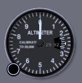
An altimeter is an instrument used to measure the altitude of an object above a fixed level. The measurement is done with an aneroid barometer. An airtight drum (the aneroid) changes shape under influence of the surrounding air pressure. The higher the altitude, the lesser the barometric pressure, the bigger the drum. This change of shape is measured and expressed in feet. However the altimeter must be calibrated during installation. During use the reading can be corrected (with a knob) for the change in air pressure caused by the weather giving a true reading. Depending on the way the altimeter is corrected it can display three different types of altitude. (More information: Altitude)
The typical altimeter has two arms, like a clock. The tall arm rotates every 1000 feet, the smaller arm rotates every 10000 feet. The small scale inside the indicator is the correction indicator that can be changed with the knob. The correction is most often in Inch Hg. In in the given image the correction is set to 29.92" Hg.
1" Hg = 1 one inch of mercury = 33.85 millibar = 33.85 hectoPascal
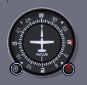
Directional Gyro
The name of this instrument describes the 2 essential parts of its characteristics:
- "directional": the instrument serves to see the direction of the plane. In other words, it serves as a compass.
- "gyro": the instrument functions by way of gyroscopes. These are objects that rotate (see the root of the word: "gyrations"). They tend to maintain their position in space.
The advantages with respect to a magnetic compass are:
- it can be set to point to the geographic north pole, not of the magnetic pole as the magnetic compass does.
- it does not have the tendency to lag behind or ahead while turning, as the magnetic compass does.
- it is not subject to magnetic influences. The magnetic compass can point in a slightly off direction due to heavy metal objects on or near the aircraft.
The disadvantage is of course that it is a more complex instrument than a magnetic compass.
Other disadvantages:
- It is heavier than a magnetic compass
- It requires a source of power, either electricity or vacuum. If the power source fails, the DG will fail. Because the gyro spins down slowly, it will slowly drift off heading. If the pilot does not notice that the vacuum or electrical system has failed, he may not realize that the DG has failed. This can lead a pilot off course.
- Gyros precess over time, and must be periodically realigned with the magnetic compass, usually every fifteen minutes.
- Turbulence or manoeuvring can "tumble" the gyro, resulting in wildly erratic readings.
Heading Bug
DG's often have a heading bug, controlled by a knob. This bug is a visual indicator of the desired course to fly. It enables the pilot to visually ensure that they are on their desired heading, and may also be coupled to the autopilot to select the heading which the autopilot will steer to.
Attitude Indicator
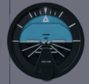
The artificial horizon, also known as the attitude indicator, simulates the position of the horizon relative to the plane. The top half of the background of the artificial horizon is blue and represents the sky. The bottom half is brown, and represents the ground. This background moves as the plane pitches forward and backward, and rolls left and right. In the center of the attitude indicator is a small dot, representing the position of the nose of the plane. To the side of this dot are lines representing the position of the wings. These parts of the attitude indicator do not move, so, when the plane pitches backward 10 degrees, the blue background shifts down 10 degrees. Most attitude indicators have major lines for every ten degrees of pitch, drawn across the center of the background. At the top or bottom of the attitude indicator is an arrow pointing out. This arrow points to corresponding markings on a ring on the attitude indicator. This ring does not move with the pitch of the plane, it only moves as the plane rolls left to right. On this ring are generally markings for 10 degrees of roll, 20 degrees, 30 degrees and 60 degrees. It is important to note that the artificial horizon indicates the orientation of the plane, and not the direction of travel. During slow flight, most planes have a high angle of attack, meaning that for straight and level flight, the nose is raised above the horizon. In this case, the attitude indicator would show the nose above the horizon (in the blue) but the airplane would be going straight and level. The artificial horizon is normally controlled by a gyro which is driven by a vacuum generated by the engine. It is possible that this vacuum can fail, especially if there is an engine failure. For this reason, the turn and bank coordinator is generally powered by an electrical generator and can be used as a backup instrument.
Turn Coordinator
The turn and bank coordinator provides two pieces of information -- the bank of the wings, and the degree of coordination between the ailerons and rudder in a turn. As the plane is rolled left and right, the wings on the turn and bank coordinator rotate as well. To make a proper turn, the ball in the middle of the turn and bank coordinator should stay centered. If the wings are rolled without enough rudder applied, the ball will move to the side. There are markings on the side of the turn and bank coordinator that indicate the amount of bank to apply to make a standard rate turn. At this rate, the plane will make one complete 360° turn in two minutes. The gyroscope powering the turn and bank coordinator is normally electrically powered, unlike the attitude indicator, which is normally powered by a vacuum generated by the engine. If one of the two instruments fails, the other one is likely to continue to work. In FlightGear, it is possible to enable automatic turn coordination, in the event you don't have rudder pedals. To do so, start FlightGear with the commandline argument --enable-auto-coordination. * todo: describe how to properly use a rudder to make a coordinated turn
Further instruments
- Vertical Situation Indicator
- Honeywell Bendix/King KLN-90B GPS
- Honeywell GPWS MK-VIII
| |||||


