Horizontal Situation Indicator
General Description
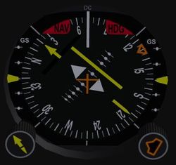
HSI is the acronym for Horizontal Situation Indicator. Sometimes it is also called Pictorial Navigation Indicator. It combines a standard Directional Gyro (DG) and Course Deviation Indicator (CDI) into one single instrument and reduces the pilots workload by displaying the aircraft's heading and position relative to a desired course in a compact manner.
The well known drift of a standard Directional Gyro is usually compensated by the use of a slaved gyro system that constantly corrects the heading indication.
The purpose of this document is to briefly describe the indicators and the usage of a HSI instrument.
Indicators
Compass Card / Compass Rose
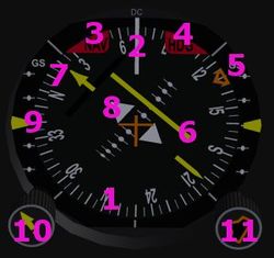
The Compass Card (1) is driven by the internal gyro. It shows the magnetic heading of the aircraft. Drift errors like in standard Directional Gyro are automatically corrected when in slaved mode.
Lubber Line
The number on the Compass Card (1) under the Lubber Line (2) shows the current aircraft magnetic heading.
NAV Warning Flag
The red NAV Warning Flag (3) indicates, that either CDI or the GS indicators are unreliable. It is driven by the signal quality of the received nav station. Do not use the CDI or GS indicators for navigation when the NAV Warning Flag is visible.
HDG Warning Flag
The red HDG Warning Flag (4) becomes visible when the speed of the directional gyro is to low. Beware that there may occur compass failures that are not indicated by the HDG Warning Flag, so compare the indicated heading with the magnetic compass on a regular basis. If the HSI is part of a slaved gyro system, the HDG Warning Flag also appears if the gyro has lost synchronization with the master. On a KCS55 this will happen, if a offset of more than 3 degrees is detected between earth magnetic field and the gyro indication. It also shows up, if the slaved gyro system is switch to manual mode.
Heading Select Bug
The orange Heading Select Bug (5) indicates the heading you (the pilot) wants to fly. It may be coupled to the autopilot so can provide the "Heading Select" function. The autopilot will try to maintain the heading indicated by the Heading Select Bug. The Heading Bug can be adjusted by the Heading Select Knob (11)
Course Deviation Bar
Like a standard Course Deviation Indicator (CDI) the Course Deviation Bar (6) shows how far the aircraft is off the selected course. When the bar is in line with the yellow arrow head and tail the aircraft is exactly on the selected course. When the bar moves to the right when looking in the direction of the arrow, the desired course is on the right (with respect to the aircraft's heading). The scale under the bar shows how far off course the aircraft is. In VOR navigation, each dot corresponds to a deviation of two degrees, allowing a total of +/- 10 degrees. During the reception of a LOC signal each dot on the CDI scale corresponds to a deviation of 0.5 degrees, a full deflection is 2.5 degrees off course. The advantage to a standard CDI is, that the entire indicator rotates with the Compass Card, giving the pilot a pictorial symbolic view of the relationship of the aircraft's heading, the selected course and the current position.
Course Select Pointer / Cursor
The Course Select Pointer (7), often simply called Cursor, is set by the pilot using the Course Select Knob (10) to the desired VOR or LOC course which is shown under the head of the arrow while the tail marks the reciprocal course.
To/From Indicator
Two white triangles (8) near the center of the display indicate, whether the selected course is to or from the tuned VOR. They correspond to the "To" and "From" flag of a standard CDI display. There is either only the "To" or only the "From" or no flag at all in the view. One will never see both flags like in the descriptive image on the right.
Glideslope Pointer
The Glideslope Pointer (9) come into view when a glideslope signal is being received during a ILS approach and the aircraft's position is within the defined range and slope of the glideslope signal. This is a very sensitive display. A full deflection correspons to a 1.4 degrees difference in the glideslope. A one dot indication showing a deviation of only 0.35 degrees off the glide slope.
Course Select Knob
Use the Course Select Knob (10) to turn the Course Select Pointer (7) to match the desired course on the Compass Card (1). This knob has the same function as the OBS knob on a standard CDI.
Heading Select Knob
The Heading Select Knob (11) moves the Heading Bug (5) to the desired heading on the Compass Card (1)

