User:Owenpsmith/Starting a model from drawings
In this tutorial, I will cover how to use a set of drawings to start a 3D model in AC3D.
Before working through this tutorial, see my previous tutorial User:Owenpsmith/Preparing_drawings_for_modelling.
Top View
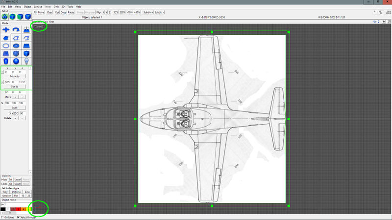
Start a new file in AC3D and select the Top view. Create a rectangle and use the tools on the left to size it to aircraft length (x axis) and wing span (y axis). Position it at 0,0,0 for now. Set the texture for this image to the plan view image created in the previous tutorial using Object -> Texture -> Load Texture. Ensure the image has the nose of the aircraft pointing to the left.
Side View
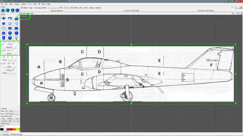
From the Front view (Front view in AC3D corresponds to the left side view for FlightGear), create a rectangle and use the tools on the left to size it to aircraft length using the side view image aspect ratio to determine height. Position it at 0,0,0; then move it upwards on the y-axis until the bottom of the tires are sitting at y=0. Set the texture for this image to the side view image created in the previous tutorial.
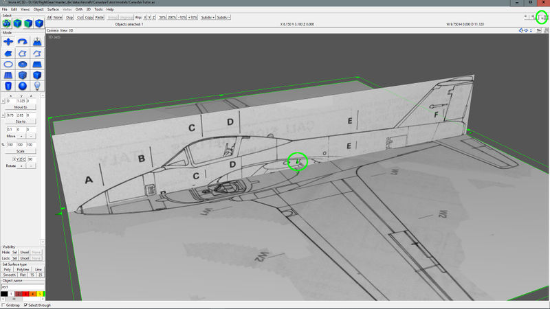
We can now view the top and side views together in the 3D view to see how they align. We can select the top view object and move it up and down with the little conic arrows in the view to align it with the different areas of the side view.
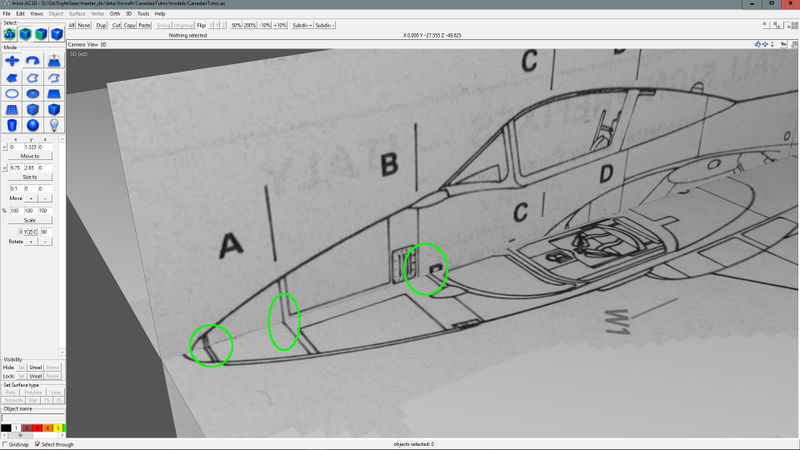
Zoom into the nose area. Here we can see the the nose light mounting points match, as do the A cross section lines, but the B cross section lines do not match. I'll have a look at some images later to see which B line is more accurate based on actual panel lines.
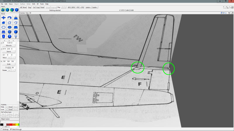
Now lets have a look at the tail which is easier to see from below, and it looks like it is aligned perfectly.
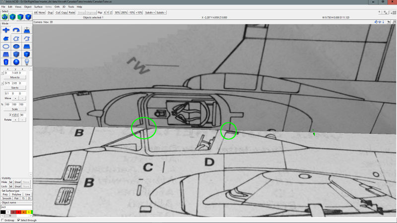
We'll also check the canopy since we know from the drawings prep tutorial that there are some inaccuracies here, and we can see here that the two drawings do not agree here so we will make a note to consult reference photos for this area.
Side View
We'll now repeat all of the steps we did with the side view, but this time for the front view which will be in the Left view in AC3D. Once we're all done we should see something like this in the 3D view:
Cross Sections
We'll now repeat all of the steps we did with the side view, but this time for the front view which will be in the Left view in AC3D. Once we're all done we should see something like this in the 3D view:
- From front view, create a rectangle and use the tools on the left to size it to aircraft wing span using the front view image aspect ratio to determine height. Position it at 0,0,0; then move it upwards on the y-axis until the bottom of the tires are sitting at y=0.
- Set the texture for this image to the side view image created in the previous tutorial.
- We now have all three basic plan views imported. We will now enure that they are all aligned with each other perfectly (or as perfectly as possible)
- Since the plan view is most reliable, we will use it as the "anchor view" and only move it up or down on the y-axis to facilitate alignment of the other views.
- move each view on its normal axis to align with each reference point on the other two views to verify alignment.
- If the rectangle objects align, but the drawing lines do not, tweak the source image in Gimp to position it correctly.
