Experimental terrain generation with GRASS
| Work in progress This article or section will be worked on in the upcoming hours or days. Note: This page features a currently unreleased feature. See history for the latest developments. |
This is a much larger undertaking than my previous learning exercise TerraGear texmapped line data
Again, I have no plan for merging this into GIT, until the concept can be proven. I am no expert in terrain engines, but I have been playing with terragear for ~6 months now, so I am also no longer a complete novice. I believe the scenery generation tools are slowly being phased out in favor of standard GIS tool, hence that is where I will start.
Here is the roadmap I plan on executing, along with some ideas on how I think frame rate improvements can be made, and allow higher detail in the scenery.
STEP 1) HGT CHOP in grass raster library.
I am writing a raster plug-in for grass that will perform the task that HGTCHOP does. Using this, I plan on generating a very simple tile (just 4 triangles, no landmass or shapefiles to generate the TIN) Being a single tile, no fitting is required.
STEP 2) SGBucket output.
Another GRASS plug-in will allow writing the TIN in simgear bucket format. I will use flightgear to verify both plugins work correctly.
STEP 3) New Bucket version
Next, I want to increment version info in the simgear tile, and allow flightgear to use both bucket formats (for backward compatibility). Here are the improvements I want to add to the tile.
- paged LOD : I want to experiment with this using OSGs Page level of detail. I will use my simple 4 triangle tiles, mixed with the normal terragear generated tiles, and learn how to incorporate this OSG feature in flightgear.
- moving map / altitude info : currently, one of the slowest (and most used) functions in flightgear, is determining the distance above ground level. If height info is stored in the tile, we could query the tile instead of intersecting the actual terrain with a line) Also, the array could store the landclass info as well, so the moving map instrument (moving map) could be higher res. Also, if the weather system, ai system, etc interacts with the terrain, it probably would be a good idea for the altitudes to remain constant instead of varying with LOD.
Step 4) Visualization tools
The wire-frame view in flightgear could be extended to help flesh out level of detail work, among other things. I propose to have a view mode where tile boundries are drawn in a much thicker line so we can see fit errors (I'm sure I'll have plenty trying to fit differing LOD tiles). The triangles themselves could be translucent, or flat shaded in a color signifying either landclass or LOD.
Step 5) LOD tiles
Write an enhanced HGTfit as a GRASS plug-in to support different LOD binding at tile boundaries)
To start, I need to make sure tile boundaries have no tears when the two tiles in question are different lod. I also plan on using the landmass shapefile to start cutting up the nice DEM mesh into irregular triangles. Using the lowest LOD (4 triangles), to see what the planet would look like from space at lowest LOD. I plan on creating several levels of detail for several tiles to experiment with the LOD engine, and see how bad the popping is.
I think it will be necessary to have a 'pin' shapefile that will be used by the scenery generation tools to pin each LOD to a constant (for cities, with lots of custom scenery, airports, etc.) In this way, each LOD within the shapefile would have the same data to eliminate popping for important areas.
LOD algorithm:
I plan on using a simple LOD algorithm based on a regular mesh (from the DEM data). Shapefile generated triangles that intersect the tile boundaries generate new nodes. The good new is, these nodes are in the same position, regardless of LOD. At a certain point, line data will not be used to generate tiles, just landclass.
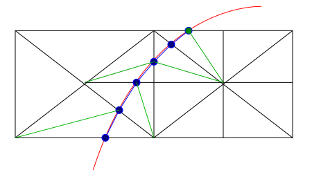
Below is the idea
On the left, the tile is 1 lod lower than the tile on the right. The landclass vector intersect the tile boundary, and triangles are generated. If the LOD is swapped (so the tile on the right is of lower detail), the boundary intersection is the same, so there should not be any tears.
What this implies, is that along the tiole boundary, there needs to be the same number of vertices. At some point, vector data will no longer be included in the tile. When this occurs, we still need to keep the intersection nodes, but terminate them as soon as possible.
