Space Shuttle
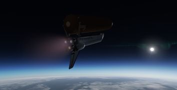
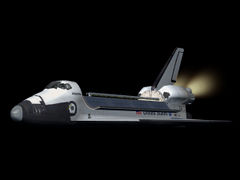
 Space Shuttle Atlantis in orbit | |
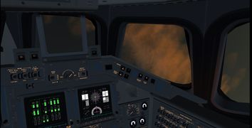
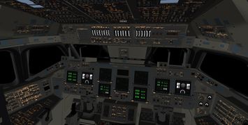
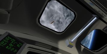
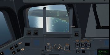
 Space Shuttle cockpit (November 2024) | |
| Type | Spaceplane, Glider aircraft, Hypersonic aircraft |
| Configuration | Delta-wing aircraft |
| Author(s) |
Shuttle development team
|
| FDM | JSBSim |
| --aircraft= |
SpaceShuttle SpaceShuttle-orbit SpaceShuttle-launch SpaceShuttle-entry SpaceShuttle-approach SpaceShuttle-TAEM |
| Status | Advanced production |
| FDM |
|
| Systems |
|
| Cockpit |
|
| Model |
|
| Development | |
| Website |
|
| Repository |
|
| Download |
|
| Forum |
|
| License | GPLv2+ |
|
| |


| Space Shuttle |
|---|
| Main article |
| Technical |
| Checklists |
| Nominal Operations |
| Nominal Operations Advanced Tutorials |
| Intact Aborts |
| The other space shuttle |
The NASA Space Shuttle was the world's first operational space plane capable of reaching orbit. It was operated from 1981 to 2011 on a total of 135 missions during which two orbiters, Challenger and Columbia, were lost in accidents.
The Shuttle launch system components include the Orbiter Vehicle (OV), a pair of solid rocket boosters (SRBs) and the external tank (ET) containing the liquid hydrogen and oxygen fuel for the engines of the orbiter. Of these, only the external tank is expendable; the SRBs splash into the sea shortly after launch and are recovered, and the orbiter itself returns to a landing site where it lands like an airplane.
The mixture of a rocket-like launch, a spacecraft-like near ballistic early atmospheric phase and an airplane like approach and landing makes the Space Shuttle a truly unique flying experience.
Project Aim
The aim of the Shuttle Project is to create a highly realistic simulation of the capabilities of the Space Shuttle in FlightGear. While most of the time the real Shuttle is under the control of automatic guidance systems, there are fallback modes to control the spacecraft manually, the so-called CSS (control stick steering) modes, and it is these modes we primarily try to implement.
In addition to the real avionics and control modes, the idea is also to provide various 'educational' modes and instruments in order to explore and appreciate certain aspects of a Shuttle mission more.
The NASA technical reports server supplies a large base of wind tunnel and in-situ performance data of both the mated launch vehicle and the orbiter, and the aerodynamics of the simulated shuttle is based on these documents. The authoritative source for procedures for trajectory management, instrumentation, limits and emergency procedures is the Space Shuttle Crew Operations Manual and currently a normal mission, i.e. ascent, orbital insertion, de-orbit, entry, terminal area energy management and landing can be flown largely 'by the book', i.e. following the real procedure for CSS.
In the following, descriptions refer to the development version - the last stable or the release version may not have all features described.
Limit and failure modeling
The project contains code to simulate the various structural and aerodynamical limits as well as component failures based on sections 4 and 6 of the Space Shuttle crew manual.
The general philosophy on limit modeling is that they can be treated dependent on a user setting as 'soft', 'hard' and 'realistic'. Where applicable, warnings when the state of the orbiter is getting dangerously close to a limit are called out in addition to a recommendation how to deal with the situation. Dependent on the trajectory of the orbiter, there may or may not be sufficient time to redeem the situation.
- soft
- Limit violations are called out, but their violation has no consequences for aerodynamics or component failures.
- hard
- Any limit violation immediately ends the simulation.
- realistic
- In reality, components do not necessarily fail immediately if used outside their design specs. This option applies a probabilistic failure model in which the chance for a component to fail grows with the degree of limit violation. The failure may or may not be immediately visible, e.g. too much qbar upon ascent may damage the heat shield, but this may not be apparent (unless specifically checked) until the heat shield fails upon atmospheric entry.
Component failure is modeled gradually where applicable - while a tire can only blow or not blow, an airfoil or a thruster for instance may lose a certain percentage of its efficiency.
In addition to failures induced by limit violations, the simulation also supports failure scenarios designed to model typical failure modes which could be expected to occur during operations, such as for instance engine failures or lock-up on ascent, coolant loop failures or leaks or similar. Rather complex chains of failures are modeled, for instance a failure of a coolant water spray boiler will lead to subsequent overheating of an APU unit - if this is not realized and proper action taken, the APU will fail subsequently, causing in turn a failure of one hydraulic system which potentially causes downstream failures of airfoil actuators or main engine gimbal capability.
The mated launch vehicle
At liftoff, thrust for the shuttle is provided by its three main engines (SSMEs) and the two SRBs. The assembled launch configuration has a height of 184.2 ft (56.1 m) and a mass of about 4,470,000 lb or 2.030 tons (in addition to payload), over 90% of this being propellant. The main engines would at this point be incapable of lifting the launch stack.
The SRBs burn an ammonium perchlorate composite fuel with a relatively low ISP of 268 s in vacuum, supplying 2,800,000 lbf of liftoff thrust each, this is supplemented by the SSME burning liquid hydrogen/oxygen with an ISP of 455 s, supplying an additional total liftoff thrust of 1,180,000 lbf. At liftoff, the shuttle hence reaches a thrust/weight ratio over 1.6, i.e. it leaves the launch pad rapidly.
Control during ascent is provided by thrust vectoring of both the SRB and SSME nozzles. The real-world CSS scheme is a 'stick controls rates' scheme which for stick to neutral does 'attitude hold' which makes it possible to control the launch trajectory very precisely.
The Solid Rocket Boosters
Each SRB weighs about 1,300,000 lb, out of which 1,100,000 is propellant weight. The propellant of the SRBs is shaped to provide a high liftoff thrust, followed by a thrust reduction during the phase of the highest dynamical pressure (max. qbar). The actual thrust as a function of time is fairly complicated:

The distribution is faithfully modeled in FG and the definitions to match the real thrust characteristics is taken from the JSBSim code repository
The SRBs can not be throttled, once ignited, they provide thrust as explained above. SRB ignition takes place some three seconds after main engine ignition, and once they ramp up to full thrust, the shuttle has no choice but to leave the launch pad. For thrust vectoring, SRB nozzles can be gimbaled up to 8 deg in both pitch and yaw axes, a roll moment is created by gimbaling the two SRBs in opposite directions.


As of May 2015, SRB separation happens automatically once the thrust drops below some threshold to avoid having to drag dead weight, but there is no provision to manually separate. The SRBs are pushed away from the remaining launch vehicle by separation motor burns. These (including the separation animation with still burning SRBs) are modeled in FG, however due to technical issues with the submodel code at high velocities, thrust of the separation motors in the sim is set larger than in reality to provide the same visual separation dynamics.
The SRBs are implemented as ballistic submodels, i.e. they follow a correct trajectory and ascent with the shuttle, however since (unlike the shuttle) they are not accelerating, they visually fall behind quite quickly.
The Main Engines
The three main engines (SSMEs) are used during ascent and burn propellant from the ET. They are mounted in a triangular configuration at the stern, tilted by 13 degrees with respect to the spacecraft main axis and can be gimbaled by 10.5 degrees in the pitch and by 8.5 degrees in the yaw axis. The reason for the tilted arrangement is to have a sensible CoG of the OV together with the ET during the later ascent stages. The heavy oxygen is stored forward in the ET, leading to a fairly forward CoG for the mated vehicle such that the SSMEs can be vectored through the CoG. This assembly is faithfully modeled in FG.

The engines can be throttled between 67 and 109% of rated power, this is necessary to keep the launch vehicle within structural limits during the high qbar phase in the atmosphere and later close to MECO as the propellant in the ET is almost depleted. Thrust increases during ascent as the exhaust gases do no longer have to push against an atmosphere. Both liftoff and vacuum thrust of the modeled engines are in agreement with published values.
Since the SSME's are mounted much closer to each other than the SRBs, the Shuttle loses significant yaw and roll maneuverability after SRB separation. However as the spacecraft is nearly out of the atmosphere by then, no such maneuverability reserves are actually needed.
In FG, the throttle controls all three SSMEs during ascent. Engines ignite once throttle is moved above 67%, this triggers the SRB ignition. If the throttle is moved below 67%, the engines will stop, however they will restart once throttle is moved again up as long as fuel is available in the ET.
The engine numbering by NASA has the center engine as number 1, the left engine as number 2 and the right engine as number 3 and these numbers are used in in-sim callouts of engine failures. For some failure modes, engines will not respond to throttle any more, in this case the cutoff switches have to be used. These are Control+q for engine 1, Control+w for engine 2 and Control+e for engine 3. An engine that has been shut down by the cutoff switch will not re-ignite.
The propellant for the SSMEs is carried in the ET. The tank has a liftoff weight of approximately 1,680,000 lb (760 tons) and a dry weight of about 66,000 lb (dependent on version - the Space Shuttle menu offers an option to fly older and heavier tanks). The ET is the only expendable component of the launch stack, it is dropped after MECO upon almost reaching orbit and then the shuttle uses the OMS to attain orbit while the tank re-enters the atmosphere half an orbit later and breaks up during entry.

In FG, the tank is normally separated using d. This is vetoed if the Shuttle has unsafe yaw, pitch or roll motion in which case the RCS should be used to stabilize the orbiter before ET separation. If an emergency separation needs to be performed, Control+d overrides the veto. At separation, a translational RCS burn will automatically push the shuttle away from the tank.
After separation, the ET will approximately co-orbit with the OV, i.e. unless the Shuttle ignites the OMS engines, the tank will be visible for a long time, slowly drifting off, and it is quite possible to use the Shuttle's RCS engines to do a visual inspection of the tank.

A note on aerodynamics of the mated vehicle
With the ET and SRBs attached, the launch stack has quite different aerodynamical characteristics than the OV alone, for instance the stack is more yaw-stable than the orbiter and its pitching moment as function of alpha and rolling moment as function of beta are very different. Where such data could be obtained from wind tunnel tests with the mated stack, it has been used in the simulation.
As in reality, the simulated shuttle has an automated downward elevon deflection schedule with Mach number upon ascent to provide further load relief for the wings (with corresponding aerodynamical forces acting).
In general though, aerodynamical effects are subleading, the ascent dynamics is dominated by the thruster forces and the flight control systems have a large margin to compensate for them.
The Ascent Performances
Space Shuttle Main Engine thrust, ISP, and consumption is now within a percent of the real datas (Dev version of December 2020) The mixture ratio in real was around 6, and it is what we observe in the sim (6 times more liquid Oxygen burnt than liquid Hydrogen). Hence, Main Engine Cut Off (MECO) time is matching real one. Plus, the propellant remaining at MECO, called the Final Performance Reserve (FPR) is now within a percent (15000 pounds). It makes launch with high payload into a high inclination Orbit (towards ISS typically) really interesting and limitating performance wise, like in real.
An interesting read about that FPR, written by a former Shuttle Flight Controller: Wayne Hale: The key is Mixture Ratio
You can find below some in sim datas compared to real one coming from the Shuttle Crew Operations Manual (SCOM).


CSS DAP schemes for ascent
During ascent, the stick controls thrust vectoring for both SSMEs and SRBs. The following two DAP schemes are available:
- Thrust vectoring
- This is the real CSS ascent mode for the shuttle in which stick motion controls rate, stick to neutral commands an attitude hold. Internally a PID controller vectors the thrusters and uses the stick input as a bias for the error. This is a very stable scheme and can be easily used to achieve high precision in controlling ascent speed or orbital inclination.
- Thrust vectoring (gimbal)
- This is an educational scheme in which the stick motion directly controls the engine gimbal, i.e. the pilot needs to do the task of the PID controller himself. To make things somewhat easier, the engines are automatically vectored through the stack's CoG, i.e. outside the atmosphere stick neutral corresponds to zero moments acting on the stack. In the atmosphere, the control input hence needs to compensate for aerodynamical forces. Launch in this scheme is fairly rough and it is not possible to reach high precision, but it is possible to fly into orbit and gain a first-hand experience of the forces acting on the stack.
m switches between the ascent DAPs. Control+m switches from the ascent to the orbital DAP modes (do not use an orbital DAP for ascent control unless you know very well what you're doing).
Ascent structural and aerodynamical limits
The following structural and aerodynamical limits need to be observed during ascent:
- Dynamical pressure qbar < 819 lb/sqf (modeled)
This is a structural limit for the orbiter and mated stack, in actual operations the orbiter should be kept below 650 lb/sqf.
- Wing bending moment coefficient CBW between -0.019 and 0.019 at max. qbar (modeled)
At max qbar, the wing bending moment is a function of Mach number and AoA. Since Mach number is close to 1.4 in this phase of the flight, this limit basically translates into alpha between -8 degrees and 2 degrees. This can only be achieved if the orbiter is in inverted flight.
- Translational accelerations Nx between 0 and 3.11 g (modeled), Ny between -0.18 and 0.18 g (not modeled) and Nz between -0.06 and 0.73 g (not modeled).
These are structural limits of the mated stack to acceleration rather than aerodynamical forces. Especially the Nx (acceleration along the orbiter axis, i.e. main engine thrust) is important and requires to throttle down the SSMEs towards the end of the burn time.
- Late ascent trajectory may not drop below 265.000 ft (modeled)
This is a heat load limit for the external tank insulation, if the thermal protection of the ET fails, it will explode.
The Shuttle in orbit
For maneuvering in orbit, the OV is equipped with three RCS thruster clusters and the two OMS engines. The propellant for these systems is monomethylhydrazine (MMH) oxydized with dinitrogen tetroxide, resulting in a specific impulse of 312 s. This is an hypergolic fuel combination (i.e. ignites automatically). OMS and RCS tanks have an interconnect valve, however only the RCS can be fired from the OMS propellant reserves, not vice versa (currently not modeled).
The OMS engines are located at the rear of the spacecraft in pods attached to the fuselage. Two of the RCS clusters are attached to the OMS pods, one is located at the spacecraft nose.
The Orbital Maneuvering System engines
The two OMS engines provide a thrust of 6,000 lb and, using the propellant reserves of 7,773 lb of nitrogen tetrozide and 4,718 lb of MMH can induce a total velocity change of about 1000 ft/sec if all propellant is spent. Typically half of this is used to push the OV into a proper orbit after ET separation and for the de-orbit burn, the rest is available for orbital maneuvers such as inclination adjustments.
Once in orbit, in FG throttle control is transferred to both OMS engines. They can be throttled from zero to 100% of nominal thrust and are automatically vectored by the flight controls through the CoG of the orbiter. The real shuttle has a DAP for thrust vectoring of the OMS engines as well as the option of using a single engine with partial thrust vectoring, only the first option is currently modeled.


OMS DAP schemes
In orbit, the throttle controls OMS engine thrust. The following DAP schemes are available:
- OMS TVC
- This is a stick-controls-rates scheme which utilizes thrust vectoring for the OMS engines. It resembles in principle the ascent thrust vectoring, except for the fact that the OMS engines are far less powerful and hence rates and the transition to the set rate are a lot slower. Note that this DAP will only control the Shuttle if the OMS is firing.
If TVC for the OMS is not feasible (for instance because the OMS engine gimbal actuators are damaged), the OMS engines can also be fired with an RCS attitude-holding rotational DAP active (for example RCS DAP-A. In this case, attitude control is provided by the RCS thrusters and thrust by the OMS engines.
The Reaction Control System
The RCS system consists of three modules, one forward at the nose and two at the OMS pods. The forward module contains 14 primary and 2 secondary thrusters, each aft module carries 12 primary and two secondary thrusters. Propellant reserves in each module are 1,477 lb of oxidizer and 928 lb of MMH. Each primary thruster has 870 lb of thrust with an ISP of 289 s, the secondary Vernier thrusters produce a mere 24 lb each with an ISP of 228 s. Due to geometric constraints, the thrusters are not aligned with the main spacecraft axes or in the same plane (for instance, there is no purely downward firing nose thruster, as its nozzle would have to fire through the heat shield). The layout of the whole system is shown below:

Not all thrusters point orthogonal, and not all thrusters have the same nominal thrust - the complete list is as follows

All of these thrusters are faithfully modeled in FG with their actual orientation and nominal thrust values, including the system of Vernier thrusters, equipping the Space Shuttle with a grand total of 51 distinct engines.
RCS DAP schemes
The real Space Shuttle has a multitude of (partially mission-specific) DAP schemes, each with different gains and deadbands, which control the thruster firing pattern in response to the controllers. A fair selection of these is implemented in FG. In the real Shuttle cockpit, there is both a rotational hand controller (RHC) and a translational hand controller (THC) to initiate either rotations of the shuttle or translational accelerations (e.g. for approach and docking). In FG, m corresponds to switching from THC to RHC to OMS control and back, ⇧ Shift+m switches between the different DAPs and Control+m is the override switch to aerodynamical controls. The HUD will display the currently selected mode for clarity.
Due to the geometry of the thruster arrangement, there is significant mode mixing. For instance, a lateral translation firing nose and right pod thruster with the same thrust would also induce a yaw motion (since the modules do not have the same distance to the CoG) and a roll (since they are not in the CoG plane and in fact not even in the same plane). In most implemented modes, the FCS logic takes care of most of these effects by firing additional thruster to cancel the unwanted motion, however in some modes this is not easily possible and mode mixing has to be anticipated and accounted for manually. This is in fact the same as in the real Shuttle.
The Shuttle has four different control pushbuttons (implemented in the menu) to control the basic way the orbital DAP works. These are AUTO, INRTL, LVLH and FREE.
If AUTO is selected, the RCS is controlled by the on-board flight software (specifically either the pointing and tracking routines available on the UNIV PTG display or the automatic burn attitude maneuvering routines available on the MNVR display). In this mode, stick control input is not used. Note that if an automatic maneuver program is selected, the controls need to be switched to AUTO prior to the start of the program. If this is not done, a SEL AUTO warning message is created.
In INRTL (inertial), the stick controls roll rates and the Shuttle holds inertial altitude for stick to neutral. The orbiting Shuttle in this mode thus has an apparent slow attitude drift with respect to the horizon.
In contrast, LVLH (local vertical, local horizon) commands an attitude hold with respect to the local horizon, i.e. the Shuttle appears not to change attitude relative to Earth. Again in this scheme, the stick controls rates.
The following DAPs are available for INRTL and LVLH:
- RCS DAP-A
- A precision 'stick controls rate' scheme in which stick to neutral commands an attitude hold. The mode has fairly strict deadbands and steep gains and hence uses comparatively much propellant to stabilize attitude.
- RCS DAP-B
- As DAP-A, but more permissive in terms of deadbands, trades less strictly stabilized attitude against reduced propellant consumption.
- RCS DAP-A VERNIER
- A 'stick controls rate' scheme in which the Vernier thrusters are used to maneuver the Shuttle. The Verniers are not very powerful and moreover fire in an awkward geometry, so there is significant mode mixing into translations when using them and the response of the Shuttle is very slow - the mode should mainly be used for automatic attitude hold as it is very propellant-friendly.
- RCS TRANS ATT HLD
- A translational DAP in which 'attitude hold' is commanded for all rotation channels. This makes this mode very stable and controllable at the expense of an increased propellant consumption - use e.g. for a precision approach to a docking.
- RCS TRANS LOW-Z ATT HLD
- No upward-firing thrusters are used in this mode to avoid plume impingement on a satellite or docking target. For this reason, forward and backward firing jets are used simultaneously which are both angled slightly upward. For -Z-translations, this causes a 12 times higher fuel consumption. For weak thrust attitude control works well, for strong thrust the controller is, without using upward-pointing thrusters, unable to completely control the pitching motion.
Finally, FREE puts the orbiter into free drift. Stick to neutral then commands all RCS jets off, and stick movements control angular acceleration. The following DAPs are available for this control:
- RCS rotation
- This is a simple scheme in which the stick motion controls thrust, i.e. angular acceleration. Stick to neutral commands no thrust, i.e. the Shuttle will continue its current rotation.
- RCS ROT TAIL ONLY
- A 'stick controls thrust' scheme in which the nose module is not used. This causes significant mode mixing.
- RCS ROT NOSE ONLY
- A 'stick controls thrust' scheme in which the OMS pod modules are not used. This causes significant mode mixing and has very limited roll control (the roll moment only comes from the position difference between left-mounted and right-mounted upward and downward firing thrusters)
- RCS translation
- A translational DAP in which the stick controls translational thrust along the spacecraft x, y and z axes. Stick to idle commands no thrust, but the Shuttle will of course retain its relative velocity to a fix point until counter-thrust is used. RCS translation can be used for emergency de-orbit burns if the OMS is not available. Limited compensation is done for cross-coupling to rotational modes.
- RCS TRANS LOW-Z
- To prevent thruster plume impingement on a docking target, say the ISS, in this mode all upward-firing thrusters are inhibited. To provide the deceleration force for a docking (which is needed in -Z direction), foreward and backward firing thrusters are used simultaneously - since they point about 10 degrees upward, this provides a downward acceleration without upward plume at the expense of 12 times higher than normal propellant consumption. There is strong cross-coupling to a pitching motion.
The following DAPs are available for re-entry (OPS 304):
- RCS ROT ENTRY
- A 'stick controls rates' DAP designed for entering the atmosphere which enforces a 'no sideslip' attitude in which the nose module is not used. This has very strict deadbands and aggressive gains to combat the yaw instability of the Shuttle upon entry, significant mode mixing and is very propellant-consuming. Do not use in orbit and only activate at the entry interface once the shuttle has the correct attitude! During entry, the DAP will gradually transfer control to the 'Aerodynamical' DAP - at qbar of 10 lb/sqft the roll axis, at 40 lb/sqft the pitch axis and at around Mach 3.5 the yaw axis.
- Aerojet
- The Aerojet DAP is close to the real entry DAP used by the Shuttle. Its RCS part works similar to RCS ROT ENTRY, but control is not transferred to to the Aerodynamical DAP but to the atmosphere part of Aerojet (see below) which employs the same rate control routines as the RCS part. The scheme also supports an automatic AoA control scheme in which the pilot only has to manage the roll axis during entry, which makes this the most easy to fly DAP for entry and atmospheric flight.
For precision control, the keyboard is a more suitable input device than a joystick or a mouse since exact nulling of rates is somewhat easier with keystrokes.
Orbital DAP configuration
As of November 2015, the Shuttle's orbital DAPs are configurable using the SPEC 20 utility. This allows to set characteristics such as the roll rates achieved for a given controller movement, deadbands for attitude and rate holding as well as to switch the nose / aft RCS pods selectively off to conserve propellant.

Note that the DAP characteristics configuration allows to specify unstable or ineffective use of the RCS, thus changes should be entered with care.
Key mapping for RCS rotation DAP
| Key | Function |
|---|---|
| 4 | Roll left |
| 6 | Roll right |
| 2 | Pitch up |
| 8 | Pitch down |
| [ | Yaw left |
| ] | Yaw right |
| 5 | Cut thrust |
Key mapping for RCS translation DAP
| Key | Function |
|---|---|
| 4 | Left |
| 6 | Right |
| 2 | Down |
| 8 | Up |
| [ | Backward |
| ] | Forward |
| 5 | Cut thrust |
.
Spacewalk
The Shuttle version as of May 2015 contains a 'proof of concept' spacewalk view designated 'EVA'. This is intended to simulate the view of an astronaut using a MMU. In the EVA view, use ⇧ Shift+E to initiate spacewalk. The stick then controls the MMU thrusters and m is used to switch between the translational and rotational modes of the MMU.
Before spacewalk is initiated, the yaw, pitch and roll rates of the Shuttle need to be nulled (since control inputs during spacewalk refer to the MMU, the Shuttle also can't be controlled from this view).
Once outside, the MMU can be used to float around the Shuttle, or to inspect co-orbiting objects. However, note that it is impossible to leave the EVA view unless the astronaut maneuvers back to the airlock. Currently it is not possible to see spacewalk from outside, nor can the view direction be adjusted - in a future implementation, spacewalk will be improved using the FG walker functionality.
Aerodynamics of the Space Shuttle Orbiter
The conditions encountered by the Space Shuttle span a wide range from a thin, rarefied atmosphere at Mach 27 to a sea level atmosphere flown at about Mach 0.6. Over this range of conditions, the handling characteristics change quite dramatically.
Somewhat simplified, one can divide the atmospheric entry in three phases - an initial near-ballistic entry phase in which airfoils are essentially useless, an aerodynamical entry phase in which the Shuttle is controlled by airfoils and aerodynamical forces are very noticeable on the trajectory, but in which the flight dynamics is completely different from that of an airplane and the final approach and landing phase during which the Shuttle is flown like an aircraft.


During these phases, control is passed from RCS jets to the airfoils - the inboard and outboard elevons at the trailing wing edges and the rudder/speedbrake at the tail stabilizer fin. The elevons can be deflected from -40 to 25 degrees, the rudder from -25 to +25 degrees. At a qbar of 10 lb/sqf roll control is taken over by the airfoils, at 40 lb/sqf pitch control is managed by airfoils and below Mach 3.5 finally yaw control is transferred, at which point the airplane-like phase of the entry starts. In addition to the primary airfoils, the Shuttle is equipped with a body flap which can be used to adjust trim.
During the first two phases, the Shuttle is flown with a high AoA (initially 40 degrees) to create a detatched bow shockwave which keeps the heat of atmospheric entry away from the fuselage. The characteristic hallmark of this attitude is that the stabilizer fin is shadowed by the wings - this renders the rudder ineffective above Mach 6 and makes the Shuttle yaw unstable against sideslip above Mach 2, i.e. any sideslip must be very accurately controlled by the FCS during entry or the Shuttle will tumble uncontrolled. This can not be done by the rudder, thus yaw jets remain crucial for controlling the Shuttle down to Mach 3.5.
Another effect is that the elevons deflected upward are in the lee of the wings, significantly reducing their effectivity as compared to downward deflections. However, in the entry regime, operating the elevons upward is more advantageous due to heating constraints.
Lift / Drag
Despite being designed for a gliding approach and landing, the Shuttle is not actually a very good glider - even close to approach, the glide ratio (i.e. L/D) reaches about 4.5, much less than most normal planes would have.

The maximum of L/D varies somewhat with Mach number, however for hypersonic flight thermal constraints force a high AoA and aerodynamical efficiency is a secondary concern. Only in the supersonic to subsonic phase is the Shuttle flown close to its optimum glide ratio.
Due to the Delta-wing design, L/D has no pronounced stall even at high AoA in any region. However, the need to have sufficient lift despite the relatively poor aerodynamics forces a high touchdown speed of about 200 kt.
Longitudinal Dynamics
In the near-ballistic entry phase, pitch is controlled by an attitude-hold mode of the RCS, however elevons are automatically trimmed by the FCS to negative (upward) deflections to take some of the load early on to conserve propellant.
The pitching moment induced by the control surface varies dramatically as function of Mach number.

As seen from the figure, at high Mach numbers the response is fairly flat (i.e. large elevon deflections are needed to control the Shuttle) and also non-linear (upward deflections cause much less pitching moment than downward deflection). In contrast, at low Mach numbers small elevon deflections already cause large moments and the response is almost linear. In all regimes, the pitching moment is normal force (i.e. AoA) dependent.
Since the elevons supply both pitching and roll control, at high hypersonic Mach numbers roll controls are close to being saturated with elevons deflected near full up. To open up better roll control, below Mach 10 the speedbrake is opened to provide a pitching moment relieving the elevons, and the Shuttle's body flap can also be trimmed upward.
Lateral stability
As mentioned above, during most of the entry phase, the Space Shuttle has no rudder action and the yawing moment as a function of sideslip angle beta is negative, indicating instability. This means that the FCS has to manage yaw stability by commanding yaw thrusters to maintain near zero beta, which is increasingly more challenging as the Shuttle penetrates deeper into the atmosphere and aerodynamical forces grow while thrust is reduced as compared to nominal vacuum values. This implies that a sizable amount of RCS propellant (about 1/3 of the capacity to be on the safe side) needs to be available before atmospheric entry.
Below approximately Mach 6, the rudder starts to contribute to yaw stability and from Mach 3.5 down to Mach 2 where the yawing moment finally becomes positive only the rudder is used. The roll behavior of the orbiter before any FCS is somewhat skittish as the roll moment as a function of roll rate is not a large damping term over most of the Mach range. The FCS of the Shuttle in FG therefore does not place yaw and roll axis directly under pilot control. The rudder is always commanded to minimize beta and no pilot input for the rudder should be needed or used unless sideslip is explicitly desired. The elevons are commanded to provide a simple roll damper to make control smoother.
The real Shuttle has in addition a NO Y JET mode to stabilize the orbiter during entry in which the elevons are used to control yaw. This leads to significantly reduced roll control since roll then needs to be driven by adverse yaw till the rudder picks up sufficient airflow. This mode has been implemented since dev version of july 2017.
A note on thruster efficiency in the atmosphere
Thrusters used in the hypersonic rarefied airflow of the upper atmosphere do not only cause the yaw, pitch and roll moment by the thrust acting at a certain distance to the CoG, but also are subject to plume impingement on the orbiter fuselage and interactions with the air flow field.
While impingement generically degrades the effectivity, the interaction moment can somewhat counter-intuitively act both directions. In particular the yaw moment is increased by the airflow, helping to stabilize the Shuttle.
As of May 2015, none of these effects is modeled in Flightgear.
Control cross couplings
The Shuttle has significant cross couplings between the elevon deflection in pitch and roll mode and the rudder as a function of Mach number, all of which are faithfully modeled in FG. One of the main effects is that upward elevon deflection alters the airflow at the aft fuselage, creating additional suction effects which alter aerodynamical forces.
In particular, at supersonic speeds yaw stability is somewhat improved at high upward elevon deflection while the effect reverses at subsonic speeds. At the same time, roll control is significantly reduced at full elevon deflection, with the effect being more pronounced at low than at high Mach numbers.
Control surface effectiveness in general drops with increasing Mach number, however the speed at which this happens is different for elevons and rudder.
Aerodynamical DAP schemes
There are two different control schemes available for the aerodynamical part of the Shuttle's flight - one of them based on the real Shuttle DAP, the other educational.
- Aerojet
- The Aerojet DAP is closest to what the real Shuttle uses. It is a scheme in which the stick commands pitch and roll rates and stick in neutral position commands attitude hold. Above Mach 3.5, in addition an automatic pitch control mode can be activated which maintains the scheduled safe entry AoA. Flying the Shuttle is very easy in this mode - there is no operational need to use trim or rudder and response to control input is crisp and precise. During entry, Aerojet can manage even agressive roll reversals inside the stable region.
- Aerodynamical
- This is an educational mode in which the Shuttle is flown similar to an airplane, i.e. the stick basically controls the airfoil positions, and in order to achieve level flight with stick neutral, trim has to be used. Since the Shuttle is yaw-unstable at high Mach numbers, this mode still has automatic stability augmentation, i.e. rudder and ailerons are commanded automatically to minimize sideslip. Entry can be flown with this mode starting in-orbit with RCS ROT ENTRY and illustrates the amount of work the rate controller has to do as well as gives a hands-on feeling for hypersonic aerodynamics. This however is somewhat challenging and it is possible to maneuver the Shuttle outside its stability envelope using too agressive maneuvers. Once below Mach 5, the Shuttle responds well and stable to direct aerodynamical control.
Entry and touchdown structural and aerodynamical limits
The following structural and aerodynamical limits need to be observed during entry and landing:
- Dynamical pressure qbar < 375 lb/sqf (modeled)
This is a structural limit for the orbiter and the airfoils, beyond this the actuators can no longer move the airfoils, leading to a loss of control. In nominal operations the orbiter should be kept below 250 lb/sqf.
- Peak temperature < 2900 F (modeled)
This is the approximate limit beyond which the thermal protection system fails, with subsequent structural failure of the overheated airframe and loss of the orbiter.
- gear extension speed < 312 KEAS (modeled)
Structural limit of the gear against aerodynamical forces.
- vertical speed upon touchdown < 9 ft/sec (modeled)
This is the structural limit of the main gear struts, and their destruction is fully modeled in 'realistic' mode.
- airspeed upon drag chute deployment < 230 kt (modeled)
The drag chute has a safety pin which disconnects the chute if the airspeed is higher than the stability limit. This is fully modeled.
- roll speed of tires < 230 kt (not modeled)
This is the certified maximal speed at which the tires don't blow.
- derotation speed < 2 deg/s (modeled)
This is the structural limit for the nose gear strut, and nose gear breakage is fully modeled.
- AoA < 15 deg on touchdown (modeled)
Beyond this angle, the body flap and tail structure of the orbiter touch the ground before the main gear does.

Systems
Most of the Shuttle's systems are designed around the philosophy that failure of any one component should allow the mission to continue and failure of two components should still allow a safe return to Earth. As a result, most systems exist triple, and the loss of one subsystem is not normally felt when operating the Shuttle, only a loss of two subsystems requires to take special action and compromises the maneuverability of the vehicle.
In the real Shuttle, many system switches have a 'GPC' (general purpose computer) setting in which the computer controls a system automatically and an 'on' setting in which the system is manually controlled. In FG, the system control is a bit simplified as no GPC or mission control is simulated and not all existing sensor readings are simulated which would be necessary for manual control. Often 'GPC' and 'on' are merged into one setting for which, dependent on system, either the user has to always control a system manually or a control routine is activated and no manual control is possible.
Electric Power Generation
Electricity aboard the Shuttle is generated by three fuel cells (FCs) which produce electricity utilizing the reaction of cryogenic hydrogen and oxygen into water (which is then used in the environment system). Each fuel cell can supply about 12 kW of power, which means plenty of redundancy given the normal power consumption of the orbiter is about 14 kW.
The fuel cells normally circulate hydrogen and oxygen in a closed loop to avoid losses, however they have to be periodically purged (reaction products vented into space) to avoid their effectivity to decrease by contamination.
As of June 2015, the power generation as well as the coarse power balance of the orbiter is modeled (i.e. switching components on which use electricity will have to be supplied by the running FCs), however not all the details of the electrical distribution system or the reactant feed lines are done. In normal operation, the electrical power system should require very little crew intervention.
Auxiliary Power Unit and Hydraulics System
Thrust vector control of the SSMEs during ascent, movement of the various aerosurfaces, deployment of the landing gear and brakes/nose wheel steering all rely on hydraulic pressure to operate.
The Space Shuttle is equipped with three independent hydraulics systems, each of them powered by an Auxiliary Power Unit (APU), a turbine utilizing hydrazine as propellant. Under normal load conditions, each APU utilized about 3 - 3.5 lb of propellant per minute. With a hydrazine load of 332 lb, this means the system can be operated for about 90 minutes under nominal conditions or be run in a power-saving mode for 110 minutes during an once around abort. This means that the APUs have to be switched off when not used - they are powered down as part of the post-MECO operations and powered up as part of the atmospheric entry preparations.
As compared to the rest of the Shuttle's systems, the APU turbines with with 180 kW power each generate a lot of waste heat which ends up warming the hydraulic fluid and the lube oil. The APUs are operated at a temperature of over 390 K (250 F) though, so for an APU cold start it takes a bit more than 10 minutes to reach that temperature. Afterwards, the water spray boiler systems have to be used to cool hydraulic fluid and lube oil - they are supplied by three water tanks containing 142 lb of water each and can spray up to 10 lb / minute for cooling purpose. Overheating APUs can not be run for more than 2-3 minutes before they fail.
When not in use, electrically powered hydraulic circulation pumps keep the hydraulic fluid moving such as to equalize temperatures in the components.
In case of a hydraulic failure, Priority Rate Limiting (PRL) for the airfoils is used to allocate the remaining power as efficiently as possible. Usually the elevons move with 20 deg/s and the rudder with 14 deg/s, however in the case of multiple hydraulic failures, these numbers are reduced to 13.9 deg/s for elevons and 7 deg/s for the rudder. The orbiter is still fully controllable in this case, but not as responsive to agressive maneuvers.
As of June 2015, the APU and hydraulic system is modeled with a fair amount of detail and operated from a dedicated menu. APUs need to be started as part of the pre-launch checklist - refer to Help/Aircraft Checklists for the detailed procedure. If the hydraulic system is not available during ascent, this will result in loss of the vehicle after SRB separation as there is no control over the Shuttle if the SSMEs can not be gimbaled. Also PRL for all airfoils is fully supported.
Operation of the water spray boilers is realistically integrated into the heat transfer model of the Shuttle (see below), including the failure of overheating APUs.
Active Thermal Control System
In orbit, the Shuttle's systems use on average about 14 kW of power, which eventually ends up heating the interior of the pressure vessel. Active cooling systems carry the heat load away and radiate it into space. A water coolant loop system takes care of the avionics bays and the cabin and exchanges heat with a two loop freon coolant system which also cools systems elsewhere in the Shuttle. The freon is circulated through the radiator panels located on the inside of the payload bay doors and dumps a maximum of about 18.000 W of heat into space.
If the payload bay doors are closed (such as during ascent or entry), the freon loop can be cooled by flash evaporators which utilize quickly evaporating water sprayed on the freon tubes as coolant. To provide the cooling performance of the radiator, this system uses about 66 lb of water per hour, i.e. can only be a temporary measure as the water storage aboard would be quickly depleted otherwise.
The heat balance in space is also influenced by the orientation of the Shuttle relative to the Sun and Earth - sunward facing surfaces tend to heat up to 350 K whereas shaded surfaces may cool down to 150 K. To ensure ice-free thruster and other exhausts, electrical heating elements may therefore be needed.
Orbiter heat management often combines cooling systems and attitude - for instance placing the OV into a tail to Sun inertial attitude minimizes incident heat and allows to cool the freon down so that it can act as a heat sink for about 15 minutes even without the radiator deployed, a technique known as 'cold soak'. Similarly, orienting the payload bay towards Earth ensures that even during the night, temperatures don't drop too much so that EVA work is possible. Temperatures can be equalized across the Shuttle by slowly rotating the spacecraft.
As of June 2015, the FG Shuttle includes a fairly sophisticated simulation of the heat balance, including incident heat flux from Sun and Earth dependent on surface normal and albedo, internally generated heat in the avionics bays, heat transport via conduction and via the cooling loops, radiated heat from the surfaces the action of the flash evaporators and the radiator. Most real heat-management techniques, including cold soak and slow rotations, are fully supported.

Thermal inertia of the Orbiter is generically high - temperatures adjust at timescales of hours rather than minutes to their equilibrium values. For educational purposes, it is possible to choose simulation options which speed up the approach to thermal equilibrium by a factor or 10 or 100 respectively - this will result in an almost immediate response of the temperature distribution to e.g. changes in attitude. These options should be used with care.
Main Propulsion System
Under the name Main Propulsion System (MPS), the various subsystems operating the SSMEs are summarized. This includes the SSME controllers (two per engine for redundancy), the propellant feeding system supplying liquid hydrogen and oxygen to the engines and the various hydraulically operated valves, a helium system to supply purge gas flows and emergency hydraulics power and finally the engines themselves.
The SSME's feed high-pressure propellants into the combustion chamber. Power for the turbo pumps is provided by partial pre-combustion of the propellant, and ullage pressure in the external tank is maintained by branching off a small fraction of vaporized propellant back into the tank. The precise opening of the propellant feeding valves which throttles the engines is governed by the controllers which in turn receive throttle commands from the Shuttle's guidance computers.
For the most part, the MPS settings are controlled on the ground prior to launch and not changed during ascent, however after MECO there are about 5,200 lb of propellant trapped in the feeding manifolds which need to be dumped. During this propellant dump, high-pressure helium is used to vent liquid oxygen through the thruster exhausts while hydrogen is allowed to boil off through the fill/drain valves.
In case of a hydraulic failure, the SSMEs can neither be gimbaled nor can their valves be changed. Each of the three hydraulic systems operated the valves of one engine, and each engine gimbal is supported by two hydraulic systems (i.e. it takes two failures to disable gimbal on one engine, but each hydraulic failure will disable valves on one engine).
If the valve settings can no longer be changed, the engine can still continue to run, but it can't be throttled any more, a condition known as 'hydraulic lockup'. It is still possible to shut down such an engine using pressure from the helium system though. Similarly, if sensors monitoring combustion chamber conditions or the command path from guidance computer to engine controllers fail, the engine is in a condition called 'electric lockup' - the controller will continue to operate it with the last known settings. Locked-up engines usually need to be shut down manually using the cutoff switches about 30 seconds prior to nominal MECO.
As of June 2015, the MPS is modeled in a good amount of detail, including most of the relevant valve settings, hydraulic and electric lockup, power failures on the engine controllers and the propellant dump sequence. The in-sim checklists provide instructions on how to execute the propellant dump and how to safe the engines for orbital operations.
Mechanical Systems
The Shuttle uses electromechanical actuators to move components which do not require hydraulic power. This includes the ET umbilical doors and the payload bay door. Each actuator contains two separate motors for redundancy, and transition time for any motion doubles if a motor is non-functional. The movement of these components is not time-critical, and hence usually slow - the complete payload bay door opening sequence takes about four minutes at normal speed to execute, twice that for actuator failures.
The ET umbilical doors are open at launch to allow the oxidizer and fuel feedlines to enter the orbiter, and they need to be closed after reaching orbit for the thermal protection during entry to be efficient. The payload bay doors are closed during ascent and entry and only opened in orbit. This is crucial, as the freon cooling loop radiators are located on the inside of the payload bay doors, i.e. the Shuttle can not remain indefinitely in orbit without opening the payload bay.
Opening or closing mechanical components usually involves unlatching, moving and possibly re-latching the components.
As of June 2015, the normal operation of ET umbilical door and payload bay door is implemented, but no actuator failures. The sequences can be driven from the GUI in automatic mode, but there is in principle support to drive them in manual mode as well as described in the Shuttle Crew Operations Manual.
Note that there's cross talk between mechanical systems and thermal modeling - tension building in the Shuttle due to uneven heating of the left and right fuselage can prevent the payload bay doors from opening or closing for instance.
Guidance systems
Automated flight
Automated flight is available for all nominal mission phases except for the final approach and touchdown (for which in reality no AP is available either) as well as all single engine loss intact ascent aborts and all two engine out contingency aborts ending in either emergency landing or crew bailout.
Unlike an airplane which is usually in or close to a steady-state equilibrium (level flight at cruise altitude) when under AP control, this is almost never the case for the Shuttle. Thus, the AP requires a context to work properly - whether a current state vector is good or bad depends on what one wants to achieve. Usually this context is a guidance target (i.e. a desired orbit, a landing site, an abort MECO condition,...) and if no such target is provided, the AP will not engage.
If there is a valid guidance target, the PFD will display error needles even if the AP is disengaged which reflect what the AP would try to do in the current situation which can be used for manual piloting. The AP can be used separately in the pitch and yaw/roll axis and independently for throttle/speedbrake control.
Once disengaged, it is as a rule not wise to re-engage the AP if the Shuttle has deviated too much from the intended state. Many AP stages are based on closed loop guidance and will try to steer back to the desired solution, however this may not be possible.
Also, automated flight does not mean the pilot can lean back and the Shuttle will handle all aborts on its own - some AP modes specifically need to be engaged or augmented by DPS options to properly work - see the Crew Operations Manual for detailed instructions. In particular, if in an emergency the wrong AP mode is engaged, the Shuttle may try to solve a kinematically impossible maneuver which usually results in loss of control.
Finally, do not expect miracles from the AP. It will usually save the orbiter even after the loss of two engines, but it may not always on its own find a viable solution to a landing site in an abort scenario. In general, automated flight is much better at manging the instantaneous state (holding an alpha schedule, aiming at a waypoint) than at longer-term planning (managing gliding range after an abort,...).
Different from the powered and gliding phase, the orbital DAP contains automatic routines for attitude management - pointing the Shuttle, tracking a location or a celestial object or automated OMS burn maneuvers.
Operating the Shuttle AP properly is very different from operating airplane APs and requires a profound knowledge of OPS sequences and major mode transitions as well as strict adherence to the published procedures.
Ascent guidance Powered Explicit Guidance (PEG)
| Note Full explanations about the Ascent guidance might be found there: Shuttle guidance - Ascent guidance Powered Explicit Guidance (PEG) |
The purpose of this section is to present and discuss about the second stage ascent guidance (post SRB sep) for Nominal Orbital Insertion, and some Intact Aborts (TAL / AOA / ATO). The guidance is based on the real closed loop used in the Shuttle, known as Power Explicit Guidance https://www.orbiterwiki.org/wiki/Powered_Explicit_Guidance.
Documentations
- A very detailled and complete topic about the guidance by Noiredd who implemented it in Matlab and KSP: https://github.com/Noiredd/PEGAS-MATLAB/blob/master/docs/upfg.md
- A deeper document with nice schematic drawings: Ascent Guidance Navigation and Control Shuttle Workbook (page 111) https://www.google.com/search?client=firefox-b-d&q=ascent+guidance+workbook+shuttle
- Original formulation of the Unified Power Explicit Guidance with equations and algorithms: ntrs.nasa.gov/citations/19740004402
- A paper about enhancements made over the years to the original ascent guidance: ntrs.nasa.gov/citations/20180002035
Overview
Second stage guidance functions very differently from first stage guidance in that second stage guidance is closed loop. Second stage guidance computes the control variables (essentially commanded attitude and attitude rates) and burn time to go (TGO) in such a way that the vehicle flies from the current state to the prescribed target conditions (altitude, velocity, flight path angle, and orbit plane) within trajectory constraints. It solves this two point boundary value problem each cycle (every 1.92 seconds). One limitation of second stage guidance is that it doesn't calculate if there is enough propellant to reach the desired MECO conditions.

The powered explicit guidance (PEG) scheme used by second stage guidance nominally operates in two phases. The first phase computes throttle and attitude commands based on three SSMEs and a constant thrust requirement until an acceleration of 3g is reached. At that time, the second phase, which uses variable throttle to maintain a constant acceleration, is entered. If an engine failure is detected, a third phase of PEG, which computes the necessary guidance commands using constant thrust to aim for the desired targets using two SSMEs, is entered (assuming no RTLS or TAL abort).
During current shuttle operations, only two phases of PEG are used, constant thrust through 3g and then variable thrust through main engine cutoff (MECO). STS-1 and STS-26, in order to prevent or reduce abort gaps, flew higher than normal trajectories, called lofted or abort shaped. This method required the third PEG phase, which ran from SRB sep to T_FAIL (I-loaded MET) and achieved lofting by assuming that an engine would fail causing loss of performance at the time T_FAIL. When T_FAIL occurred, PEG stopped assuming that an engine would fail. A drawback with this method was discovered later, however. The lofted trajectories caused “black zones,” or regions where an unsurvivable entry/pullout condition would be created if two engines actually did fail (CA). For this reason and the fact that abort shaping costs thousands of pounds of nominal ascent performance (payload), the I-load, T_FAIL is now set to zero, and lofted trajectories are not currently planned.

Second stage guidance performs yaw steering to achieve the desired orbit plane. The desired orbit plane is defined by the unitized negative angular momentum vector (I-loads), commonly referred to as the IY vector. The x and y components of the IY vector define the nodal crossing, while the z component defines the inclination. For missions which do not involve rendezvous with a vehicle already in orbit (referred to as the “target”), the IYs are defined during the flight design process approximately 6 months prior to launch. These missions employ “earth fixed” yaw steering since the trajectory relative to the earth remains the same regardless of launch time. In order to successfully launch into orbit and rendezvous with another vehicle already in space, the orbiter must end up in the same orbital plane and altitude as the other vehicle.

Forty seconds prior to MECO, guidance no longer seeks to achieve the altitude and orbital plane position targets. Common terminology is, “at MECO minus 40 seconds, the position constraints are released.” Without this constraint release, when TGO becomes small, a small change in position error would produce large changes in the thrust turning rate vector and over controlling would result. Note also that the cutoff time (TGO) calculation includes the predicted velocity change from the time minimum throttle is commanded to burnout. This corresponds to the predicted tailoff impulse from each active SSME and is known as fine count. Fine count occurs 10 seconds prior to MECO for nominal ascent, ATO, and TAL and 6 seconds prior to powered pitchdown for RTLS. It is at fine count where second stage, closed loop guidance is terminated and the SSMEs are commanded to a lower power level, usually 67% for three engines running or 91% for one or two engines running (note that the SSMEs aren't throttled back until powered pitchdown during an RTLS). Thereafter, the flight path angle constraint is released, such that TGO is computed solely on the desired velocity change (VGO). When guidance sees the shuttle at the correct inertial velocity (VI), all SSMEs are commanded to shut down.
Entry guidance algorithm
| Note Full explanations about Entry shuttle guidance might be found there: Shuttle guidance - Entry guidance algorithm |
A topic speaking about the entry guidance algorithm.
Documentations
I didnt use hyperlinks to avoid NASA ntrs server spam from forum robots
- A quick overview of the Descent guidance from the Space Shuttle Technical Conference: ntrs.nasa.gov/citations/19850008593
- A deeper look into the Entry equations formalism with that paper that you might find under: Shuttle Entry Guidance JSC-14694
- Entry guidance formulation requirements (code): ntrs.nasa.gov/citations/19800016873
All the documentations linked in the Entry/TAEM rework are even more useful now, as almost all the parts of Entry guidance are simulated and displayed parameters fed with consistent datas. https://forum.flightgear.org/viewtopic.php?f=87&t=38777
TAEM/Approach guidance algorithm
| Note Full explanations about TAEM and Approach/Autoland guidance might be found there: Shuttle guidance - TAEM/Approach and Autoland guidance |
This section speaks about TAEM and Autoland guidance.
Documentations
Overview
The last link mentionned above is pretty interesting to see the evolution of TAEM guidance and how it was handled. The main document I used include the Optional TAEM Targeting (OTT) logic that has been used since STS-5 (before the HAC was a circle with less Energy options for test flights).
After STS-5, HAC could be flown with the different options we are used to see . Overhead or Straight-In HAC; and Nominal Entry Point (7Nm in final) or Minimal Entry Point (4Nm in final)

Another option called - final radius shrinking - is included in that TAEM guidance version. It allows the final HAC radius (2.3 Nm) to decrease up to 0.8 Nm if we are low during the HAC.

The whole logic is organized through several functions that are called during all the TAEM phase at a rate between 160 and 980ms. It ends at 10000 feet (Approach and Landing interface) where the Auto Land logic kicks in (quite the same logic with tighter gains).

Let's go briefly through each functions. The first function that is not mentionned is a frame coordinate converter from a Greenwhich frame into a runway centered frame.

Avionics and DPS
The avionics of the Space Shuttle is fairly faithfully reproduced by the simulation, see the dedicated article on Space Shuttle Avionics for an overview. The implemented screens include routines to monitor the various systems as well as guidance navigation and control for all mission stages.

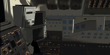
All nine MDUs of the forward panel are usable and display the DPS and MEDS screens of the Shuttle - this includes launch and entry guidance routines, TAEM guidancs as well as orbital tracking and pointing management. In addition, HUDs for Commander and Pilot are provided.


An alternative display for all phases of flight is provided by the FG-native the HUD. This has four different modes - ascent, orbit, entry and approach, and dependent on the HUD mode, different information relevant for the mission phase is displayed. In all cases, the current CSS DAP is identified in the upper left.
There is a calculator for orbital elements available, determining perigee and apogee, orbital inclination and longitude of the ascending node (the latter is currently not so useful as it is obtained in an inertial coordinate system). Based on these orbital elements, the groundtrack map displays current position of the Space Shuttle, selected landing site, ground track history and a prediction of the future orbit - if the perigee is below the surface of Earth, the prediction ends at the estimated ballistic impact point (note that due to the aerodynamical capabilities of the Shuttle, the actual landing site can be within a cross range of about 1000 miles around that point dependent on how the trajectory is managed during the entry phase).
Payload handling
The Space Shuttle is equipped with the capability to release payload from the bay into space, or to catch a payload from space and deposit and secure it in the bay. For this, the Remote Manipulator System (RMS) arm in combination with the payload retention system is used.


RMS arm operation
The RMS arm is a fairly complicated device with six different joints, each allowing rotation along one specific axis, which is formed after the human arm. The nomenclature is borrowed from this analogy, so there is a shoulder yaw, a shoulder pitch, an elbow pitch, a wrist pitch and wrist yaw and roll joints. Each of the joints can only be moved a certain angular range. At the end of the RMS arm is the end effector which is the device which can attach to a payload.
The RMS arm can be driven in various modes. The simplest of these are the single joint or the direct mode in which each joint angle is controlled separately, i.e. the arm is extended by first selecting a joint, then commanding it to either increase or decrease angle, before the next joint is selected.
Since this is cumbersome, the more natural control modes allow to use the stick (or whatever control device is attached) to directly move a reference point. In the ORB UL x/y/z mode (UL stands for 'unloaded') the reference point is the tip of the end effector, i.e. using the stick just moves the joint angles such that the end effector moves along the x, y, or z-axis and otherwise keeps its attitude. The ORB UL yaw/pitch/roll mode in contrast keeps the end effector's position and just changes its attitude.
The real Shuttle has additional modes in which the reference point is in the center of the payload, or in which the reference coordinate system is changed from the Shuttle's coordinate system to a system co-moving with the end effector camera - these are as of August 2015 not implemented in FG.
All modes except single and direct joint driving have software safety stops when the joints approach their limit extensions. Since in its stowed position, two of the joints are in the software stop region, it is necessary to directly drive shoulder pitch and elbow pitch out of their soft stop region to be able to use the more sophisticated control modes - see the diagram below for the reach angles of each joint.

Finally, the RMS arm is secured by a shoulder brace to make it cope with launch acceleration. This brace needs to be removed before the arm can be operated, and the arm itself needs to be powered, deployed and unlatched.
Payload retention system
The payload retention system is a series of latches which hold a payload in the bay. Before a payload can be lifted out of the bay, these latches need to be released. Similarly, if a payload is returned into the bay, ready-to-latch indicators show when it has reached the correct stowing position and it can only be safely released from the RMS arm once the latches are closed.
The real Shuttle has three different payload positions with corresponding latch controls, as of August 2015 only one payload position is supported in FG. Likewise, currently only a simple demo satellite with no proper folding/unfolding animation is available as visual payload (note that a payload mass affecting the FDM can also be chosen in the 'Fuel and Payload' dropdown menu).
Mission phases
The various phases of a Shuttle mission are generically subdivided into launch, orbit, entry, TAEM and approach. These can directly be accessed by appending the mission phase to the command line. This will automatically start the Shuttle in the correct configuration and the correct state for the mission selected. For instance, --aircraft=SpaceShuttle-TAEM --airport=KVBG will initialize a TAEM approach into Vandenberg, --aircraft=SpaceShuttle-orbit --lat=30.0 --lon=0.0 --heading=90.0 will initialize the Shuttle in a 30 deg inclination orbit.
Note that --aircraft=SpaceShuttle-entry combined with an airport as location will not initialize you on an entry trajectory to that airport since the entry interface is several thousand miles away from the landing site and moreover the trajectory needed is not unique but depends on what you fly - you need to initialize the entry interface location by hand using latitude and longitude.
Specific information on the mission phases can be found in the following articles:
Documentations
Flying the Shuttle - Space Shuttle Checklists
Nominal Operations
Flying the Shuttle - Orbital Operations
Flying the Shuttle - Final Approach
Nominal Operations Advanced Tutorial
Flying the Shuttle - Launch And Post Insertion Advanced
Flying the Shuttle - Deorbit Preparation Advanced
Flying the Shuttle - Deorbit Burn and Final Entry Preparation Advanced
Flying the Shuttle - Entry TAEM and Landing Advanced
Intact Aborts
Flying the Shuttle - Intact Abort Procedures Overview
Flying the Shuttle - Return To Launch Site RTLS
Flying the Shuttle - Transoceanic Abort Landing TAL
Glossary of acronyms
| AoA | Angle of Attack |
| APU | Auxiliary Power Unit |
| CoG | Center of Gravity |
| CSS | Control stick steering |
| DAP | Digital autopilot |
| ET | External tank |
| EVA | Extravehicular Activity (spacewalk) |
| FC | Fuel cell |
| FCS | Flight Control System |
| ISP | Specific impulse |
| MECO | Main Engine Cutoff |
| MMH | monomethylhydrazine (a propellant) |
| MMU | Manned Maneuvering Unit |
| MPS | Main Propulsion System |
| OV | Orbiter vehicle |
| OMS | Orbital Maneuvering System |
| PRL | Priority Rate Limiting |
| RCS | Reaction Control System |
| RHC | Rotational Hand Controller |
| RMS | Remote Manipulator System |
| SRB | Solid rocket booster |
| SSME | Space Shuttle main engine |
| TAEM | Terminal Area Energy Management |
| THC | Translational Hand Controller |
| TVC | Thrust Vector Control |
Latest development snapshot
The latest development version (possibly unstable) is found in a dedicated repository on SourceForge. You can download the latest snapshot from http://sourceforge.net/p/fgspaceshuttledev/code/ci/development/tarball. Stable updates are pushed to FGAddon periodically.
Documentation
In addition to the original NASA Shuttle Crew Operations Manual and the DPS dictionary which are found in the Documentation/ folder of the spacecraft, a Flight Manual specifically for the operation of the Flightgear simulation is available (standard edition free of charge for Flightgear users):
(click picture to download)
Educational Links / Shuttle technical files
General Space knowledge and tutorials
Basic of Space Flight Book https://er.jsc.nasa.gov/seh/spaceflt.pdf
Thorsten LEO Tools https://forum.flightgear.org/viewtopic.php?f=87&t=35213
Orbiter Space Sim Beginners tutorial https://www.youtube.com/watch?v=bOxpvqrqLAo
FAA Space Basics ( Must read) https://web.archive.org/web/20210530202242/https://www.faa.gov/about/office_org/headquarters_offices/avs/offices/aam/cami/library/online_libraries/aerospace_medicine/tutorial/section3/spacecraft_design/
Rendez Vous Theory
https://www.baen.com/rendezvous https://www.baen.com/rendezvous-part2
Educative links
Why the wings of the Shuttle Stay on it during Maximal Aerodynamical pressure phase https://www.aiaa.org/docs/default-source/uploadedfiles/about-aiaa/history-and-heritage/why_the_wings_stay_on-ehrlich.pdf?sfvrsn=801c62b5_0
Space Shuttle Aerodynamics and Flight Dynamics Overview https://web.archive.org/web/20210127120052/https://www.nasa.gov/centers/johnson/pdf/584730main_Wings-ch4d-pgs226-241.pdf
Space Shuttle Systems
Space Shuttle Systems in depth
Nasa Space Shuttle systems Exhaustive Manual: SCOM https://web.archive.org/web/20200602210929/https://www.nasa.gov/centers/johnson/pdf/390651main_shuttle_crew_operations_manual.pdf
Nasa Data processing system dictionnary, or "What does that page of my shuttle computer" https://web.archive.org/web/20210226022241/https://www.nasa.gov/centers/johnson/pdf/359895main_DPS_G_K_7.pdf
Crew Software Interface ( Nice introduction to Shuttle Computer and handling) https://web.archive.org/web/20210226022249/https://www.nasa.gov/centers/johnson/pdf/383444main_crew_software_interface_21002.pdf
Workbooks ( Detailled part on some Shuttle systems and procedures, SCOM complement)
APU (How Hydraulic is provided to Shuttle systems https://web.archive.org/web/20210226022251/https://www.nasa.gov/centers/johnson/pdf/383439main_apu_hyd_wsb_21002.pdf
Air Data Systems (What are the equivalent of Pitot Tubes in the Shuttle) https://web.archive.org/web/20210226021921/https://www.nasa.gov/centers/johnson/pdf/383438main_air_data_system_workbook_21002.pdf
Environmental Control and Life Support System ( How is cooled the Shuttle ) https://web.archive.org/web/20210226004654/https://www.nasa.gov/centers/johnson/pdf/383445main_eclss_21002.pdf
Navigation Aids ( or how the Shuttle find precisely the runway during entry) https://web.archive.org/web/20210226022247/https://www.nasa.gov/centers/johnson/pdf/383450main_navigation_aids_workbook%2021002.pdf
Intact Ascent Aborts ( Procedures after ONE engine failure) https://web.archive.org/web/20210226022307/https://www.nasa.gov/centers/johnson/pdf/383447main_intact_ascent_aborts_workbook_21002.pdf
Contigency Aborts Procedures after more than ONE engine failure/degradation https://web.archive.org/web/20210226011554/https://www.nasa.gov/centers/johnson/pdf/383441main_contingency_aborts_21007_31007.pdf
And much more that are not publicly available but findable here after a subscription ( A true Space Gold Mine)
https://www.nasaspaceflight.com/l2/
Space Shuttle Checklists
Flight Data Files Bible Site https://web.archive.org/web/20211020173004/https://www.nasa.gov/centers/johnson/news/flightdatafiles/index.html
Annotated and condensed one Flying the Shuttle - Space Shuttle Checklists
A bit more organized:
More informations about Flight Data Files in SCOM part 3
Normal situation Checklists
Post Insertion https://web.archive.org/web/20210417211853/https://www.nasa.gov/centers/johnson/pdf/567074main_PI_135_F.pdf
Deorbit Preparation https://web.archive.org/web/20210424062634/https://www.nasa.gov/centers/johnson/pdf/492871main_D-O_G_Q_5.pdf
Entry
https://web.archive.org/web/20210424062633/https://www.nasa.gov/centers/johnson/pdf/381558main_ENT_G_H_8.pdf https://web.archive.org/web/20210417204127/https://www.nasa.gov/centers/johnson/pdf/567069main_ENT_135_F.pdf
Non Normal situation Checklists
In the Normal situation Checks above, there are off nominal sections to deal with non critical procedures.
For time critical procedures that must be performed within 5 minutes, there are the so called Pocket checklists ( Ascent, Orbit and Entry). They are almost the same.
Ascent
The Ascent PCL contains procedures that safe systems for continued flight. It also contains orbiter systems powerdown procedures. https://web.archive.org/web/20210407003811/https://www.nasa.gov/centers/johnson/pdf/366508main_APCL_G_O_1.pdf
Orbit
At the initiation of the post insertion phase, the Orbit PCL is utilized. This PCL contains critical orbiter systems malfunction responses and powerdown procedures. The orbit PCL often refers to the orbiter Malfunction Procedures (MAL) Book for detailed troubleshooting.
Contigency Deorbit in case of Severe malfunctions in Orbit ( Loss of cooling systems, or massive elec failure,..) that would lead to a fast deorbit.
Entry
The Entry PCL contains critical contingency systems malfunction responses that allow safe continuation of the pre-deorbit through early entry phases along with orbiter systems powerdown procedures.
Space Shuttle Books
To Orbit and Back Again
Like a SCOM, less cryptic, full of anecdotes. https://www.springer.com/gp/book/9781461409823
Into to the Black
Book about STS 1, it reads like a Thriller https://www.thespacereview.com/article/2982/
Shuttle Down
Book about an hypothetical scenario. What if the Shuttle was launched from vandenberg and would have diverted to Easter Island :) [url]https://www.goodreads.com/book/show/549127.Shuttle_Down[/url]
Videos
A compilation of in FG Sim videos about the Space Shuttle
Space Shuttle Launch Flight Gear with STS 133 Real Voices
Space Shuttle RTLS Abort with OPS 6 real guidance
Space Shuttle TAEM KSC Runway 33:HAC and Final Approach
On orbit timelapse [3]
Mission reports
A compilation of Space Shuttle stories / mission reports.
Shuttle approaches contest [4]
The Van Allen Mission [5]
STS 62 Polar Mission [6]
Meeting Hubble [10]
From Ground to Orbit [11]
From Orbit to Ground [12]
Return to Launch Site [13]
Transoceanic Abort Landing in Zaragoza [14]
Abort Once Around [15]
Contingency Abort: Landing in Bermuda [16]
Contigency Abort: East Coast Abort Landing [17]
Electrical failure and TAL [18]
Impending Loss of Hydraulics and AOA [19]
Fictionnal Mission into Polar Orbit from Vandenberg [20]
Deorbit and Landing in Easter Island [21]
Triple Engine Failure TAL [22]
Massive electrical failures and Contigency Deorbit // Off Nominal Checklist walkthrough [23]
Single Engine TAL after Droop [24]
Gallery
| There is a category with screenshots of the Space Shuttle. |

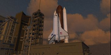
KSC launch photorealism

KSC launch photorealism

Vandenberg site photorealism

White Sands site photorealism

Edwards site photorealism

Bermuda site photorealism
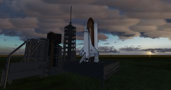
View on the Pad Pilot Side
Rainy Pad
Shuttle Launch
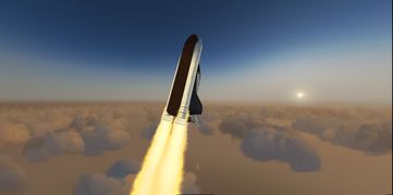
Shuttle Launch
Shuttle Launch

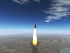
Launch smoke trail
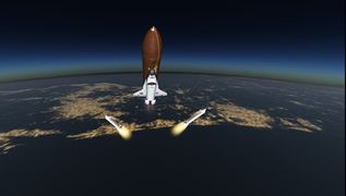
SRB separation
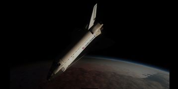
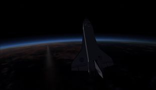
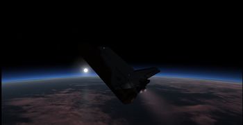
Accelerating to orbital speed
Improved visuals of the exhaust flame
Shuttle 3d cockpit
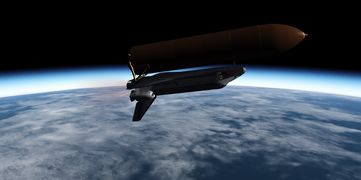
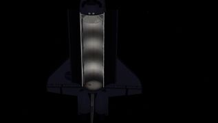
External tank separation
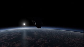
A view of Earth after reaching orbit
The ET seen from the Shuttle
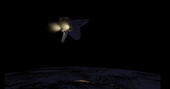
Full OMS thrust
Lightings game in Orbit
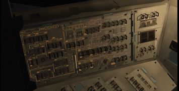
Shadows and lights on the L2 Commander panel
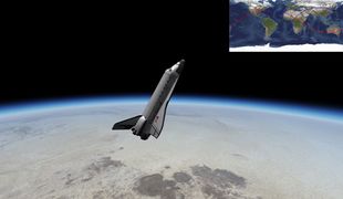
The orbiter high over Africa
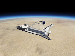
Handling payload with the RMS arm
Payload Lightings

Sunrise over Antarctica
Sunrise over Antarctica 2
The OV in orbit at Sunset
The OV in orbit at Sunset 2
RTLS Abort
Orbital insertion burn at night
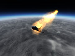
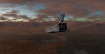
Atmospheric entry
Tiles Glowing Red
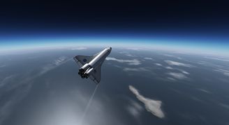
High bank angle maneuver to control vertical speed
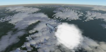
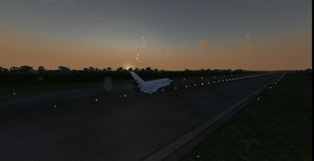
During TAEM the Space Shuttle goes subsonic
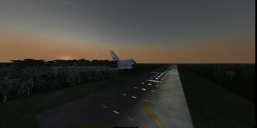
On final approach into Eastern Island Emergency Landing Site
Final in Trondheim
Pre-flare
Flare
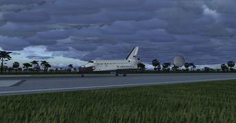
Touchdown in KSC
Wheels stop in KSC


