User:Zayamatias/Adding HID devices to FlightGear
Adding HID devices to FlightGear hopes to explain how to set-up any HID device to work with FlightGear in a step-by-step easy to follow guide, it is my belief that any HID can and will work with FlightGear
First disclaimer: The HID subsystem seems to be working only under Linux and MacOS, I am not sure if one day it will work in Windows. Second Disclaimer: This guide was done under an Ubuntu distribution, this means that other distros may vary slightly. Last but not least: I take no responsibility in the unlikely event of you breaking your HID device by using this guide
Getting started
Before starting, there are a couple of tools you need to install:
- HIDVIZ
- This tool will allow you to have a look at the inner workings of your HID device, I'll talk about it later.
- VS Code
- I use this for creating the XMLfiles and the Nasal code, as it has very nice extensions for this, but this is not mandatory and you can use anything you are used to.
- Python
- I've created some quick and dirty tools under Python to test the device, so make sure Python (3.9 at least) is installed in your system if you want to use them.
The Device
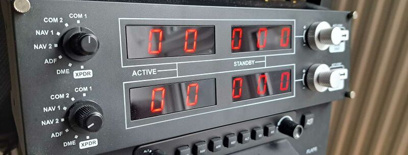
For this guide, I'll be using the Saitek/Logitech radio panel as an example that would hopefully help you with any other device.
So let the fun begin!
Understanding what's the name of the device
Start your PC and go to the terminal, do not connect any device yet, and let's see what has been detected in the USB connections:
lsusb
Bus 002 Device 003: ID 045b:0210 Hitachi, Ltd
Bus 002 Device 002: ID 045b:0210 Hitachi, Ltd
Bus 002 Device 001: ID 1d6b:0003 Linux Foundation 3.0 root hub
Bus 001 Device 012: ID 138a:00ab Validity Sensors, Inc.
Bus 001 Device 011: ID 093a:2510 Pixart Imaging, Inc. Optical Mouse
Bus 001 Device 008: ID 258a:0001 SINO WEALTH USB KEYBOARD
Bus 001 Device 005: ID 214b:7250 Huasheng Electronics USB2.0 HUB
Bus 001 Device 003: ID 04f2:b669 Chicony Electronics Co., Ltd HP HD Camera
Bus 001 Device 013: ID 8087:0aaa Intel Corp. Bluetooth 9460/9560 Jefferson Peak (JfP)
Bus 001 Device 004: ID 045b:0209 Hitachi, Ltd
Bus 001 Device 002: ID 045b:0209 Hitachi, Ltd
Bus 001 Device 001: ID 1d6b:0002 Linux Foundation 2.0 root hub
By issuing the 'lsusb' command you can see what the PC has detected as connected devices, no sign yet of my radio panel, so let's connect it now and issue the same command:
lsusb
Bus 002 Device 003: ID 045b:0210 Hitachi, Ltd
Bus 002 Device 002: ID 045b:0210 Hitachi, Ltd
Bus 002 Device 001: ID 1d6b:0003 Linux Foundation 3.0 root hub
Bus 001 Device 012: ID 138a:00ab Validity Sensors, Inc.
Bus 001 Device 011: ID 093a:2510 Pixart Imaging, Inc. Optical Mouse
Bus 001 Device 008: ID 258a:0001 SINO WEALTH USB KEYBOARD
Bus 001 Device 005: ID 214b:7250 Huasheng Electronics USB2.0 HUB
Bus 001 Device 003: ID 04f2:b669 Chicony Electronics Co., Ltd HP HD Camera
Bus 001 Device 013: ID 8087:0aaa Intel Corp. Bluetooth 9460/9560 Jefferson Peak (JfP)
Bus 001 Device 014: ID 06a3:0d05 Saitek PLC Pro Flight Radio Panel
Bus 001 Device 004: ID 045b:0209 Hitachi, Ltd
Bus 001 Device 002: ID 045b:0209 Hitachi, Ltd
Bus 001 Device 001: ID 1d6b:0002 Linux Foundation 2.0 root hub
Interestingly, I now see the Bus 001 Device 014: ID 06a3:0d05 Saitek PLC Pro Flight Radio Panel being shown in my connected devices.
If your device does not show up, make sure that it is properly connected, and powered if needed, and as a last resort try to see if it is connectable to any other PC. If still it does not show, then either probably it is not an HID device, or it is not working at all.
So now, save the name Saitek PLC Pro Flight Radio Panel, we will need it afterwards.
Making sure your Linux user has full access to the device
One of the issues with Linux and HID devices is user permissions, Linux is quite secure and usually will let a specific subset of users use the HID device, so let's make sure your user has access to this particular one.
Let's go back to the 'lsusb' output from earlier:
Bus 001 Device 014: ID 06a3:0d05 Saitek PLC Pro Flight Radio PanelSee that there are 2 hexadecimal numbers in there: 06a3:0d05 ? The part before the colon is the vendor id (or VID for shorts) and the second one is the product ID (or PID) for shorts. The first one will change depending on the manufacturer of the device, you can check here if you're curious.
Now, keep those numbers somewhere safe, we will need them.
One of the first parameters to have access to a HID device is to make sure that the user belongs to a group we can refer to, for example in Ubuntu, if your user has to have access to joysticks (as any kind of gaming device) then it has to be added to the 'js' group, like this:
usermod -a -G examplegroup exampleusernameWhere examplegroup is js in our case and exampleusername is your Linux user. You will need to run this as root, so add the 'sudo' prefix before the command
sudo usermod -a -G examplegroup exampleusernameRemember this 'sudo' for later on.
Ok, so now let's make sure your user belongs to the js group:
groups
pi adm dialout cdrom sudo dip plugdev lpadmin lxd sambashare usb wireshark js
I can see my user's last group is js, well done, one thing less.
Now we have to make sure that your device is recognized as a joystick, for this, you need to create a new udev rule. Do not worry about what this means exactly (although you can read about it at Opensource.com)
We need to tell your Linux install that the Saitek device is a joystick (fun fact, my Linux install though the panel was a mouse, and moving the dials would move the actual mouse...) :
There are several ways you can do this but this one works for me:
Open the (or create a new) rule file under /etc/udev/rules.d/, I have called it 00-local.rules
so, let's go for it:
nano /etc/udev/rules.d/00-local.rulesThis will open an editor (nano), feel free to use any editor, just remember that you have to be root to be able to save the file.
Add the following line to your file:
SUBSYSTEM=="input", ATTRS{idVendor}=="06a3", ATTRS{idProduct}=="0d05", ENV{ID_INPUT_JOYSTICK}="1",ENV{ID_INPUT_MOUSE}="0", TAG+="uaccess"We now are saying to Linux that the device with VID 06a3 and PID 0d05 is a joystick and not a mouse (do those numbers ring a bell?)
Just for completion's sake, there's another possibility to do this, alas less 'secure' by Linux standards. You can create a new file: /etc/udev/rules.d/99-hid.rules and in it add the following lines:
SUBSYSTEM=="usb", ATTRS{idVendor}=="06a3", ATTRS{idProduct}=="0d05", MODE="0666"
KERNEL=="hidraw*", ATTRS{busnum}=="1", ATTRS{idVendor}=="06a3", ATTRS{idProduct}=="0d05", MODE="0666"
This will give anyone access to the device in question (and hence less secure in Linux terms).
So now we have setup the device so it is a joystick and your user can access it. Let's go and play with it:
Understanding your device's Inputs and outputs
Make sure your device is connected and powered if needed, Once you're sure, launch hidviz:
(I have compiled the version from the link I've put in the tools section, I won't be explaining how to build it since it is already explained in the GitHub page)
./hidvizThis will present you with the following screen:
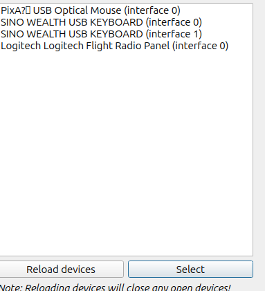
Click on 'Select Device', this will ask you for your password to gain root access if you have not run the command as 'sudo'
You should see the Saitek pro panel there, select it:
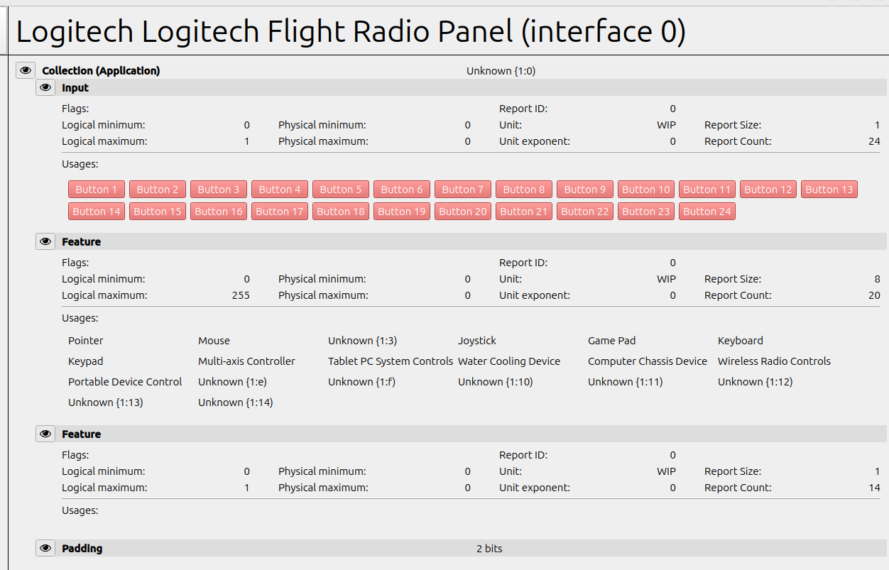
As you can see, there are 24 buttons (bits) (top section Collection/Input) and there seem to be 2 features. One containing 20 (report count) 8-bit values (report size) with a maximum logic value of 255 and then another report of 14 times 1-bit values (fun fact, when I started with the HID devices I didn't use hidviz, so I'm intrigued by this second feature report which I was not aware of!).
For completion, HID devices (as far as I am aware) have 3 types of reports, input (which is data sent from device to PC) output (which is data sent from PC to device) and feature, which seems to be also in the PC to device category. As you can see, here you have 1 input (buttons) 2 features (we'll talk about these later) and a padding of 2 bits, this is there because usually reports need to be of a specific size (multiplier of 24 if I remember correctly), if you do your maths: 24bits + 20*8 (160 bits) + 14 bits = 198 + 2 padding bits = 200 bits in total, ok it does not add up, go figure, but this is not the only weird thing about this descriptor, look at the actual features described: water cooling device! either Saitek devs had a great sense of humor or they didn't spend much time figuring out how to do proper HID reports. In any case, I was expecting also to have an output report instead of a feature report and each report with its unique ID. Saitek: some improvements are needed here! All of this to say: HID is a big grey area amongst manufacturers, so your levels of patience to make the device work may vary
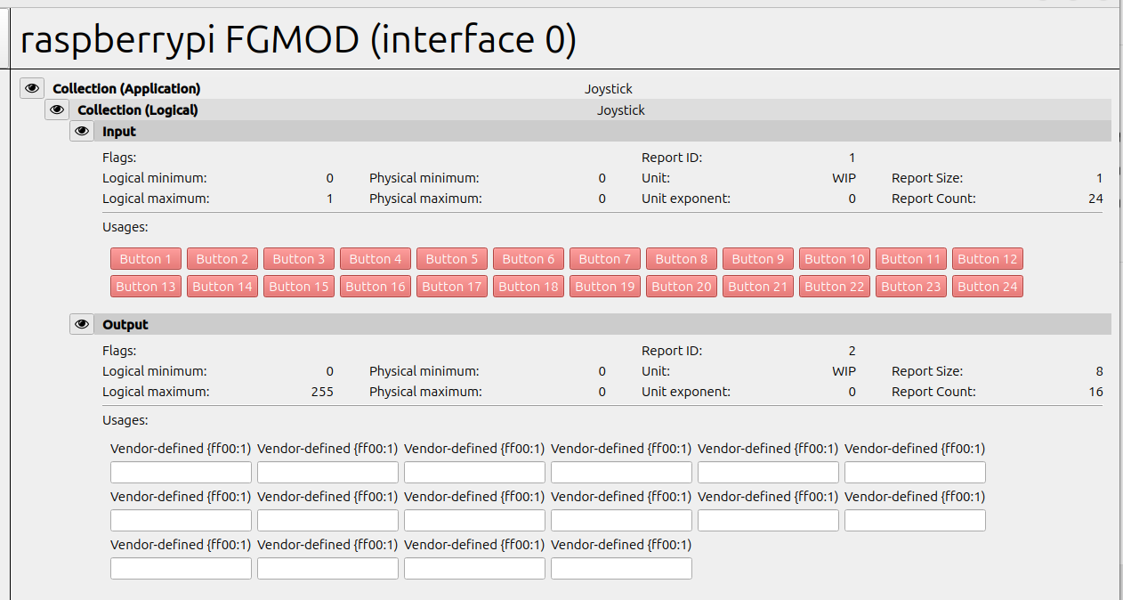
If the descriptor would have been set up properly, you should have seen something like this for the output reports: (This is for one of my custom devices):
This would have allowed you to easily enter values in the output report and understand how the device treated data, alas, it is not the case for the Saitek device, so let's go Python!
Understanding how data is received and processed by your device:
So we now know a little bit more about the device, it has 24 buttons, and it has 20 possible inputs (spoiler: the Saitek panel has 4*5 segment displays, could it be?? Hmmmm...)
Let's try Python.
First, you need to check which hidraw Linux device corresponds to your actual device, Linux will map your device under /dev/hidrawx and to find it, create script (call it findhid.sh):
#!/usr/bin/env bash

FILES=/dev/hidraw*
for f in $FILES
do
  FILE=${f##*/}
  DEVICE="$(cat /sys/class/hidraw/${FILE}/device/uevent | grep HID_NAME | cut -d '=' -f2)"
  printf "%s \t %s\n" $FILE "$DEVICE"
done
And then
chmod 775 findhid.sh
And finally execute it:
./findhid.sh
hidraw0 	 SYNA3083:00 06CB:8265
hidraw1 	 ELAN2514:00 04F3:288A
hidraw2 	 SINO WEALTH USB KEYBOARD
hidraw3 	 SINO WEALTH USB KEYBOARD
hidraw4 	 PixA琀 USB Optical Mouse
hidraw7 	 Logitech Logitech Flight Radio Panel
so, this means that our Saitek panel is linked to /dev/hidraw7, nice!
Now, open an editor and create hidtest.py:
import os

def send_data_to_hidraw(data, hidraw_path):
    try:
        # Open the HIDRAW device
        hidraw = os.open(hidraw_path, os.O_RDWR | os.O_NONBLOCK)

        # Write data to the HIDRAW device
        os.write(hidraw, bytes(data))

        print("Data sent successfully to HIDRAW device.")

        # Close the HIDRAW device
        os.close(hidraw)
    except Exception as e:
        print("Error:", e)

if __name__ == "__main__":
    # Define your data to send
    data_to_send = [0x01, 0x02, 0x03,0x01, 0x02, 0x03,0x01, 0x02, 0x03,0x01, 0x02, 0x03,0x01, 0x02, 0x03,0x01, 0x02, 0x03,0x01, 0x02, 0x03]  # Example data

    # Specify the path to your HIDRAW device
    hidraw_path = "/dev/hidraw7"  # Replace with the actual path to your HIDRAW device

    # Send the data to the HIDRAW device
    send_data_to_hidraw(data_to_send, hidraw_path)
Two important things: change hidraw_path to your devices' correct link and make sure that the data_to_send variable is of the same length as the report we found in hidvix, in this case, we have 20 times one byte, noted in hex format in Python (0xXX).
Small clarification, as you can see I'm sending 21 bytes, the reason behind this is that the first byte indicates the report_id you're sending to, in the case of the Saitek panel, there's no real report id, so whatever you put in the first byte will still work. Make sure you consider this when testing your device.
Now run the Python script
python3 hidtest.py
Nothing happened? well, this could be down to several factors:
- No permissions (go back to the start) - The report is of incorrect size (try again, remember you are sending bytes, so a report of 8 times 1 bit, equals a nibble (half byte), and the same goes for bits. The safest thing to do is to count the number of bits and then divide by 8, this is the number of bytes you ill need to send)
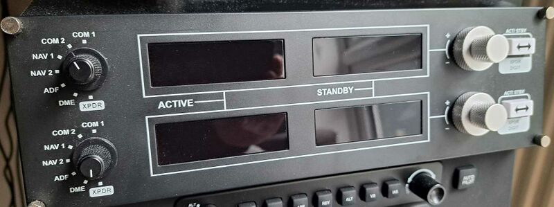
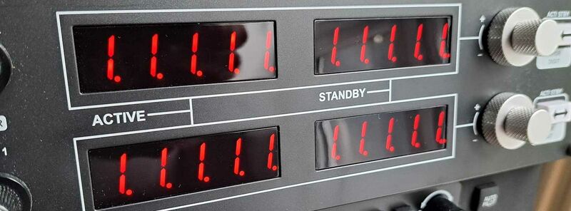
If you are lucky you should go from this:
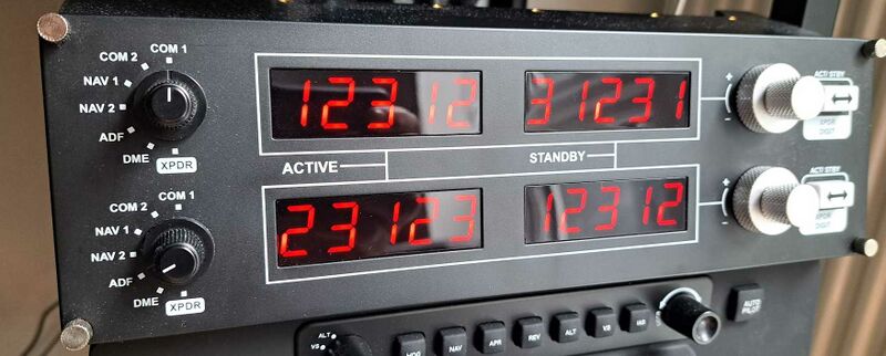
To this:
Congratulations, you just sent the first pieces of data to your device. As you can see it shows the numbers in the order we sent in the report, or so it looks like.
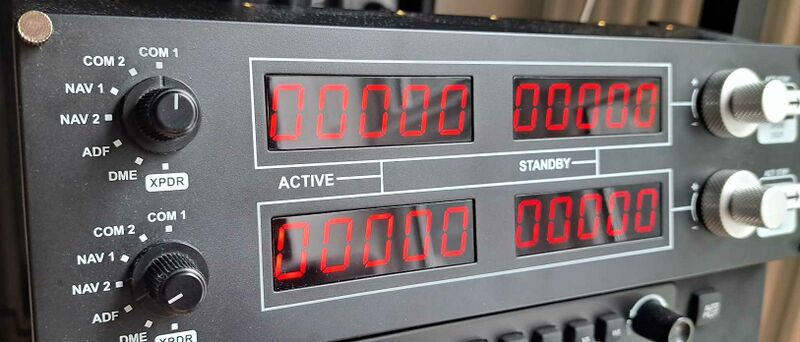
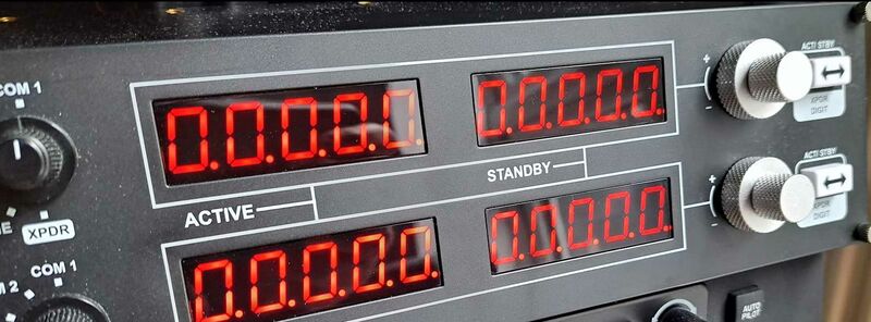
Now, it is a game of sending reports with different values and understanding what's your device's reaction, for example, if I sent just zeroes:
Now the fun starts.
So this is a radio panel right, aren't radio frequencies supposed to have a 'dot' somewhere, but hey, how do I tell the device I want to have a dot? Let's think, why do I have the possibility to send 20 bytes, with a maximum value of 255? Makes no sense right, watch byte represents a number in the panel that can go up to 9 (0 to 9), so anything else is overkill, unless...
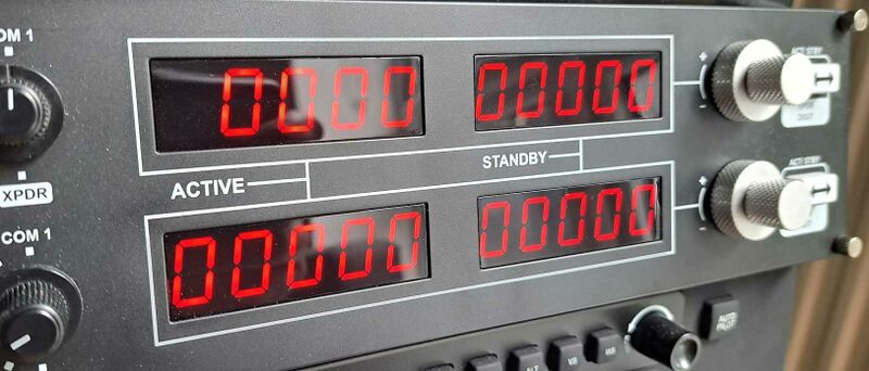
Let's try to send something over 9, for example the second byte in data_to send I put it as 0x0A (A is 10 in hex), what happened there?
My first digit just switched off!! Interesting so now I can show numbers of less than 5 digits (XPDR, DME, hmm...) because I can switch any digit off as I please, let's try that again:
Nice!
So we now know, 0 to 9 is the digit in question, 10 switches off the digit, but what about the 'dot' ???
Let's send 11 (0x0B):
Disappointment, nothing happens, let's keep trying other values.
Hey what's this?
I was at 209, so what if I send all 208 (0xD0)
Ok! So if I want to add a dot to any digit, I need to add 0xD0 the the value, so 0xD0 for 0, 0xD1 for one and so on)
What if I continue?
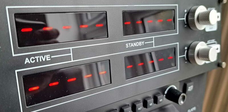
This is what happens with 224 (0xE0)
I get a 'dash'!
And there's nothing else interesting in the tests, the numbers repeat a lot, but basically when now:
0 to 9 -> the numbers in each digit 10 -> Switch off the digits 208-217 -> The numbers with a dot (to the right) 224 -> A dash
Important point, we have not used any proprietary drivers or anything that could be linked to Saitek's proprietary development (AFAIK, I'm not a lawyer), we're just sending data to the device.
Now that we know the logic, we're ready to go to the next step, make it work in FlightGear! [To be continued in next post]
So now we have understood (more or less) how our device works, how we can send data to it, and what this data does.
Let's fire up FlightGear.
Making sure FlightGear detects the device
The first thing we need to do is to launch FlightGear with debug on, to do this make sure you set the log level to debug via the --log-level=debug flag, do this either in the command line or if you use the launcher, in the additional settings.
I would also recommend you to capture the output of the log:
./dnc-managed/run_fgfs.sh --launcher 2>&1 | tee log.txt
This is my command, yours may be slightly different, the important part is the 2>&1 | tee log.txt at the end of it.
launch FG and let the log start capturing all the information we need.
Once the airplane's cockpit is showing up, you can shut down FlightGear, that's all we need for now.
Open the log.txt and start looking for the name of your device, you should see things like:
  225.20 [DBUG]:input      name=<null>, node=<null>
  225.20 [DBUG]:input      name=Logitech Logitech Flight Radio Panel, node=/dev/input/event23

  225.26 [INFO]:input      Logitech Logitech Flight Radio Panel_0 has event button-0 modifiers=0 value=1
  225.26 [INFO]:input      Logitech Logitech Flight Radio Panel_0 has event button-1 modifiers=0 value=0
  225.26 [INFO]:input      Logitech Logitech Flight Radio Panel_0 has event button-2 modifiers=0 value=0
  225.26 [INFO]:input      Logitech Logitech Flight Radio Panel_0 has event button-3 modifiers=0 value=0
  225.26 [INFO]:input      Logitech Logitech Flight Radio Panel_0 has event button-4 modifiers=0 value=0
  225.26 [INFO]:input      Logitech Logitech Flight Radio Panel_0 has event button-5 modifiers=0 value=0
  225.26 [INFO]:input      Logitech Logitech Flight Radio Panel_0 has event button-6 modifiers=0 value=0
  225.26 [INFO]:input      Logitech Logitech Flight Radio Panel_0 has event button-7 modifiers=0 value=0
  225.26 [INFO]:input      Logitech Logitech Flight Radio Panel_0 has event button-8 modifiers=0 value=0
  225.26 [INFO]:input      Logitech Logitech Flight Radio Panel_0 has event button-9 modifiers=0 value=0
  225.26 [INFO]:input      Logitech Logitech Flight Radio Panel_0 has event button-266 modifiers=0 value=0
  225.26 [INFO]:input      Logitech Logitech Flight Radio Panel_0 has event button-267 modifiers=0 value=1
  225.26 [INFO]:input      Logitech Logitech Flight Radio Panel_0 has event button-268 modifiers=0 value=0
  225.26 [INFO]:input      Logitech Logitech Flight Radio Panel_0 has event button-269 modifiers=0 value=0
  225.26 [INFO]:input      Logitech Logitech Flight Radio Panel_0 has event button-270 modifiers=0 value=0
  225.26 [INFO]:input      Logitech Logitech Flight Radio Panel_0 has event button-271 modifiers=0 value=0
  225.26 [INFO]:input      Logitech Logitech Flight Radio Panel_0 has event button-left modifiers=0 value=0
  225.26 [INFO]:input      Logitech Logitech Flight Radio Panel_0 has event button-right modifiers=0 value=0
  225.26 [INFO]:input      Logitech Logitech Flight Radio Panel_0 has event button-middle modifiers=0 value=0
  225.26 [INFO]:input      Logitech Logitech Flight Radio Panel_0 has event button-side modifiers=0 value=0
  225.26 [INFO]:input      Logitech Logitech Flight Radio Panel_0 has event button-extra modifiers=0 value=0
  225.26 [INFO]:input      Logitech Logitech Flight Radio Panel_0 has event button-forward modifiers=0 value=0
  225.26 [INFO]:input      Logitech Logitech Flight Radio Panel_0 has event button-back modifiers=0 value=0
  225.26 [INFO]:input      Logitech Logitech Flight Radio Panel_0 has event button-task modifiers=0 value=0
  225.26 [DBUG]:input      using InputDevice Logitech Logitech Flight Radio Panel_0

  225.28 [WARN]:input      Unhandled HID generic desktop usage:1
  225.28 [INFO]:input      Logitech Logitech Flight Radio Panel_0: add:unknown, bits: 0:8, report=0
  225.28 [WARN]:input      Unhandled HID generic desktop usage:2
  225.28 [INFO]:input      Logitech Logitech Flight Radio Panel_0: add:unknown-1, bits: 8:8, report=0
  225.28 [WARN]:input      Unhandled HID generic desktop usage:3
  225.28 [INFO]:input      Logitech Logitech Flight Radio Panel_0: add:unknown-2, bits: 16:8, report=0
  225.28 [INFO]:input      Logitech Logitech Flight Radio Panel_0: add:joystick, bits: 24:8, report=0
  225.28 [WARN]:input      Unhandled HID generic desktop usage:5
  225.28 [INFO]:input      Logitech Logitech Flight Radio Panel_0: add:unknown-3, bits: 32:8, report=0
  225.28 [WARN]:input      Unhandled HID generic desktop usage:6
  225.28 [INFO]:input      Logitech Logitech Flight Radio Panel_0: add:unknown-4, bits: 40:8, report=0
  225.28 [WARN]:input      Unhandled HID generic desktop usage:7
  225.28 [INFO]:input      Logitech Logitech Flight Radio Panel_0: add:unknown-5, bits: 48:8, report=0
  225.28 [WARN]:input      Unhandled HID generic desktop usage:8
  225.28 [INFO]:input      Logitech Logitech Flight Radio Panel_0: add:unknown-6, bits: 56:8, report=0
  225.28 [WARN]:input      Unhandled HID generic desktop usage:9
  225.28 [INFO]:input      Logitech Logitech Flight Radio Panel_0: add:unknown-7, bits: 64:8, report=0
  225.28 [WARN]:input      Unhandled HID generic desktop usage:10
  225.28 [INFO]:input      Logitech Logitech Flight Radio Panel_0: add:unknown-8, bits: 72:8, report=0
  225.28 [WARN]:input      Unhandled HID generic desktop usage:11
  225.28 [INFO]:input      Logitech Logitech Flight Radio Panel_0: add:unknown-9, bits: 80:8, report=0
  225.28 [WARN]:input      Unhandled HID generic desktop usage:12
  225.28 [INFO]:input      Logitech Logitech Flight Radio Panel_0: add:unknown-10, bits: 88:8, report=0
  225.28 [WARN]:input      Unhandled HID generic desktop usage:13
  225.28 [INFO]:input      Logitech Logitech Flight Radio Panel_0: add:unknown-11, bits: 96:8, report=0
  225.28 [WARN]:input      Unhandled HID generic desktop usage:14
  225.28 [INFO]:input      Logitech Logitech Flight Radio Panel_0: add:unknown-12, bits: 104:8, report=0
  225.28 [WARN]:input      Unhandled HID generic desktop usage:15
  225.28 [INFO]:input      Logitech Logitech Flight Radio Panel_0: add:unknown-13, bits: 112:8, report=0
  225.29 [WARN]:input      Unhandled HID generic desktop usage:16
  225.29 [INFO]:input      Logitech Logitech Flight Radio Panel_0: add:unknown-14, bits: 120:8, report=0
  225.29 [WARN]:input      Unhandled HID generic desktop usage:17
  225.29 [INFO]:input      Logitech Logitech Flight Radio Panel_0: add:unknown-15, bits: 128:8, report=0
As you can see from the log, there are already several interesting pieces of information:
The device has ben recognized! 25.20 [DBUG]:input name=Logitech Logitech Flight Radio Panel, node=/dev/input/event23
It has detected the buttons 225.26 [INFO]:input Logitech Logitech Flight Radio Panel_0 has event button-0 modifiers=0 value=1
And even the feature reports 225.28 [WARN]:input Unhandled HID generic desktop usage:2
225.28 [INFO]:input Logitech Logitech Flight Radio Panel_0: add:unknown-1, bits: 8:8, report=0
As you can see, we have everything under control, FG has detected the device and has detected the different buttons and feature reports. All of these are called 'events' by FlightGear.
Important point, when we're going to be creating the properties files, we need to refer to the name you see in the logs, as strange as it sounds, you will get different buttons name not necessarily in a sequential order (things like thumb2, or button-333).
The properties files
The way that FlightGear communicates with the devices is via XML files located under the FlightGear directory ('~/.fgfs' for most linux installs) and then under Input, with 2 different options, either 'Joysticks' or 'Event':
drwxr-xr-x 2 pi pi 4096 Mar 27 16:12 Event
drwxr-xr-x 2 pi pi 4096 Apr  1 15:49 Joysticks
The joystick directory will hold, amongst others, the files that are created automatically by the joystick configurator within the simulator, the directory we're interested in is this:
~/.fgfs/Input/EventNote, there's no problem in having both a joystick file and an event file for the same device, I do have this for my Honeycomb alpha, where the axes are in the joystick file and the rest of the buttons in the event file (which allows me to go beyond the 32 button limitation, yes, you can use this HID way of doing things for devices over 32 buttons).
So let's start writing. First of all, create an empty file called 'YOURDEVCIE.xml' (this is an example and the filename is not relevant as FG will read inside to understand to which device each file belongs (although I name it as the device with '-' just for clarity, for example for the Saitek panel Logitech-Logitech-Flight-Radio-Panel.xml )
Put the XML header:
<?xml version="1.0"?>
<PropertyList>
  <name type="string">Logitech Logitech Flight Radio Panel</name>
  <debug-events type="bool">true</debug-events>
This will indicate FG this is the file for your device, as the name tag defines it.
If you plan to have some 'logic' in your properties file, add the nasal tags:
<?xml version="1.0"?>
<PropertyList>
  <name type="string">Logitech Logitech Flight Radio Panel</name>
  <debug-events type="bool">true</debug-events>
  <nasal>
    <open>
      <![CDATA[]]>
Your basic file is starting to get some form. Now we need to start defining what do we do when each of the events is triggered: I'm going to paste below the bindings (that's how it's called in FG) for the fact that you have switched the upper selector of the radio panel into 'comm1' mode:
  <event>
    <desc>UK COMM1</desc>
    <name>button-1</name>
    <binding>
      <command>property-assign</command>
      <property>/saitek/RP/upknoba</property>
      <value>/instrumentation/comm/frequencies/selected-mhz</value>
    </binding>
    <binding>
      <command>property-assign</command>
      <property>/saitek/RP/upknobb</property>
      <value>/instrumentation/comm/frequencies/standby-mhz</value>
    </binding>
    <binding>
      <command>property-assign</command>
      <property>/saitek/RP/upknobt</property>
      <value>5</value>
    </binding>
    <binding>
      <command>property-assign</command>
      <property>/saitek/RP/upknobsw</property>
      <value>/instrumentation/comm/frq-swap-btn</value>
    </binding>
    <binding>
      <command>property-assign</command>
      <property>/saitek/RP/upknobmax</property>
      <value>137</value>
    </binding>
    <binding>
      <command>property-assign</command>
      <property>/saitek/RP/upknobmin</property>
      <value>118</value>
    </binding>
    <binding>
      <command>property-assign</command>
      <property>/saitek/RP/upknobfstep</property>
      <value>1</value>
    </binding>
    <binding>
      <command>property-assign</command>
      <property>/saitek/RP/upknobhstep</property>
      <value>0.025</value>
    </binding>
    <binding>
      <command>nasal</command>
      <script>refreshPanels();</script>
    </binding>
  </event>
Do not be scared by that size! I like to make things generic, so you will see a lot of reference and proxy properties being set that would allow to handle the logic of what happens when we're in 'comm1' mode in the upper panel.
First of all we set the property saitek/RP/upknoba to /instrumentation/comm/frequencies/selected-mhz
    <binding>
      <command>property-assign</command>
      <property>/saitek/RP/upknoba</property>
      <value>/instrumentation/comm/frequencies/selected-mhz</value>
    </binding>
We then set the standby frequency to the /saitek/RP/upknobb property
    <binding>
      <command>property-assign</command>
      <property>/saitek/RP/upknobb</property>
      <value>/instrumentation/comm/frequencies/standby-mhz</value>
    </binding>
Then the property /saitek/RP/upknobt to 5, which is the number of digits a frequency has
    <binding>
      <command>property-assign</command>
      <property>/saitek/RP/upknobt</property>
      <value>5</value>
    </binding>
Then the 'swap' button to change frequencies
    <binding>
      <command>property-assign</command>
      <property>/saitek/RP/upknobsw</property>
      <value>/instrumentation/comm/frq-swap-btn</value>
    </binding>
The some max,min and incremental values, and last but not least, I call the refresh panel function (that I've created) to put the proper values in the panels:
    <binding>
      <command>nasal</command>
      <script>refreshPanels();</script>
    </binding>
  </event>
This has to be done to every single button in the device, so they act the way you expect them to do. You can check the full file at the bottom of this post.
Ok, so we have the buttons set up, now we want the display to show the proper values:
We use the same tag, event, only that now we have to link a property to the event, so FG will send that value to the output/feature report in the proper position.
Before we continue, remember that in the log, we saw things like:
  225.28 [WARN]:input      Unhandled HID generic desktop usage:1
  225.28 [INFO]:input      Logitech Logitech Flight Radio Panel_0: add:unknown, bits: 0:8, report=0
And I did mention that the name that you saw there is the name that should be used for the event, in the case of unknown, you need to add the suffix -0 for the first one, the rest will already have it -1, -2,-3 etc..
Let's add the event to the XML:
  <event>
    <desc>RADIO INDICATORS</desc>
    <name>unknown-0</name>
    <setting>
      <property>/saitek/RP/ULpanel/digit1</property>
    </setting>
  </event>
You're telling FlightGear to watch for the property /saitek/RP/ULpanel/digit1 and set its value to the vendor-0 byte.
As you can see there's a strange property there: saitek/RP/ULpanel/digit1. This property is of my choice and you can create any property you want to be sent to the device. Remember that in this particular case, we have a value for each digit, so we cannot send the actual value, we have to slice it so we send each digit in the correct position.
And then again, do the same for the rest of the events.
Once the events have been set and saved, you can launch FG to see if it worked!
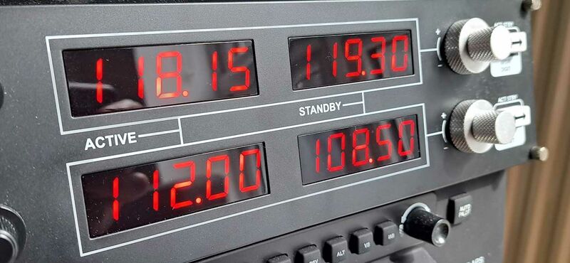
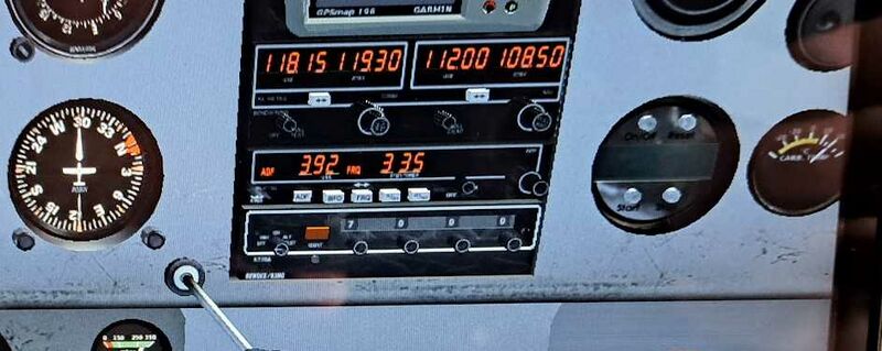
Yes! I see the same frequencies in the panel
as in the simulator
Of course, every time you modify the frequencies in any of the sim or panel, the other one reflects the same value as expected.
You can have a look at the complete xml file, where you can see I use nasal heavily to do some extra logic, for example, do not turn on the panel unless the contact is set on the aeroplane, how I use the swap button to select the digit when in XPDR mode, and so on. There is no limits to what you can do once you understand the properties and what you're able to do with them.
I hope I have not forgotten anything essential and I also hope this has helped. I'm really looking forward to other devices becoming available in FG.
This also opens the possibility of creating your own devices, have a look at my repo.
