User:Zakharov/zkv1000 user guide
Introduction
The zkv1000 is an instrument which concentrates some other instruments in only one single and simple interface. It is largely inspired from the famous display parts of Garmin Primus 1000. Once said, the zkv1000 is definitively not an exact replica of the Garmin Primus 1000, and isn't intended to be one. Sorry about that.
But by flying with zkv1000 you have the certitude that you're the nearest to the real zkv1000, it can't me more realistic :)
Depending of your aircraft you may have in your cockpit different configurations, and some unavailable entries. Even we are in a sim, so there is no limit in the way to get full instrumented glide plane it may be interesting to limit the use of certain functions depending of the aircraft. This has to checked with the aircraft maintainer, or if you feel free with the GPL licence you may modify the aircraft to get the desired functions to work (see installation guide)
Overview
There is two device types: MFD and PFD. You may find in your aircraft a configuration with only one of those, one of each or one MFD and two PFD. But there may be other configurations if the aircraft maintainer has decided it.
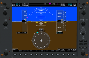
PFD
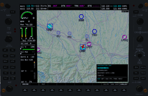
MFD
Softkeys codes
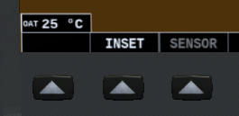
BrightWhite on Black : available menu entry.
Grey on Black : not yet implemented entry or not available in this aircraft
Black : no entry
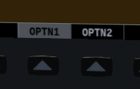
Black on White : activated entry
UI code and usage
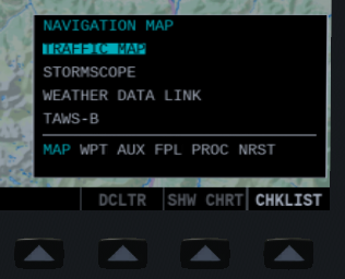
Selected entry is in Black on LightBlue
Available entry is LightBlue on Black
Unavailable entry is White on Black
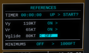
entries with marks < or > or both are entries with limited number of choices.
First choice doesn't show the < char, last one doesn't show the > char. All other show both < and >
Navigate from an entry to the next or the previous by turning the large FMS knob, modify the value of the entry by turning the small FMS knob.
Primary Flight Display
You just jumped into your Aircraft, depending of the scenario for it you may need to switch up electric system or some button(s) to get the zkv1000 up. Please refer to the aircraft manual.
Airspeed indicator
The indicated airspeed tape is in knots or km/h, the unit is refered as speed init later in this documentation. You can modify the speed unit by the dedicated window.
The black pointer shows the current IAS.
On the tape major ticks are displayed with 10 speed units interval, minor ticks at 5 speed units interval. The trend can show up to 1000 speed units. A pink trend vector shows the estimated speed in the next 6 seconds (in the limit of +/- 30 speed units).
There may be some Vspeeds marks (pink, text in white) specific to the aircraft (cf installation guide). It is possible to modify these values of the Vspeeds references (value and display, except Vne) as described later in this document
The black pointer will take a red color if IAS exceeds the defined Vne.
The true airspeed is shown under the speed tape, and the ground speed, in the same unit than IAS
Altitude indicator
The altitude tape is in feet or meters, the unit is refered as altitude unit later in this documentation. The altitude can show from -990 to 99990 altitude units. The black pointer shows the current indicated altitude (determined from the air pressure), 20 altitude units graduated. A trend vector indicates the readched altitude in the next 6 seconds in the limit of +/- 300 altitude units.
The barometric setting is shwon just under the altitude tape. It is graduated in inHg or hPa, which is refered as pressure unit later in this documentation. The pressure unit can be modified to hPa or inHg quickly by using the softkey menu PFD > UNITS and press INHG or HPA
| Note It won't be saved this way for another session. To save it see the zkv1000 settings part in this documentation |
The setting to standard barometric value (29.92inHg or 1023hPa) can be automatically set by the menu PFD > STD BARO. The barometer setting is essential and can be done by turning the BARO knob in front of the device (left side, under the COMM knob).
The selected altitude is indicated by a lightblue bug along the altitude tape. It is blocked at the upper or lower corner of the tape until the tape has in its range the selected altitude. While the selected altitude isn't in the +/- 300 altitude unit range a black box indicates the selected altitude above the altitude tape. This box disappears when the indicated altitude is +/- 100 altitude unit of selected altitude.
Vertical speed indicator
The vertical speed indicator is on the right just near the altitude tape, and is graduated with major ticks every 1000 ft/min or m/min refered as vertical speed units later in this documentation. Minor ticks are displayed every 500 vertical speed units.
A black pointer containing the vertical speed with 10 vertical speed units precision moves along the non-moving tape. If the vertical speed exceeds +/- 4500 vertical speed units the pointer is locked to the upper/lower of the non-moving tape, and the vertical speed is detailed inside the pointer.
Attitude indicator
Pitch scale is graduated 10° up to 80°, with minor marks 5° interval up to 25°, and every 2.5° below 20° pitch. The horizon line is part of the pitch scale, and represents a pitch of 0°.
The roll scale is the 120° arc. The inverted triangle represents 0° roll. Major ticks represent 30° and 60°, minor ticks represent 10°, 20° and 45°.
The slip skid indicator is the bar beneath the roll pointer. The Slip Skid indicator moves laterally away from the pointer to indicate the lateral acceleration.
Horizontal situation indicator
The HSI displays a rotating compass card in a heading-up orientation. Letters indicate the cardinal points and numeric labels occur every 30°.
Major tick marks are at 10° intervals and minor tick marks at 5° intervals.
A digital reading of the current heading appears on top of the HSI.
Course Deviation Indicator
The HSI contains a Course Deviation Indicator (CDI) with course pointer, TO/FROM indication and a sliding deviation bar.
GPS, VOR1 and LOC1 have single line arrow, while VOR2 have two lines arrow.
GPS CDI is available only if a course has been set via the route manager, VOR and LOC show arrow when the active NAVAID is received.
Adjust heading
Turn the HDG knob to adjust the heading, doing so the heading bug will be positionned along the compass.
A window showing the desired heading is shown for 3 seconds.
Adjust selected course
Select the corresponding GPS, NAV1 or NAV2 display by pressing the CDI softkey, then turn the CRS knob to adjust the desired course for VOR.
Unless you aren't in OBS mode you cannot change the course for GPS. To do so, select GPS by pressing CDI softkey, then OBS softkey is displayed as available. To enter in OBS mode, press the OBS softkey, now you can adjust course by turning the CRS knob.
Set your zkv1000 preferences
Press the MENU button, a window appears with settings. Navigate into the available settings by turning the outter FMS knob. The inner FMS knob changes the selected setting.
To quit and save changes press CLR.
Brightness
You can adjust the luminosity of the whole device (PFD and MFD). Select the first entry Brightness and turn the inner FMS knob to increase or decrease brightness (from 0% to 100%). This setting isn't saved from a session to another.
Device lights
For a night flight you may need to change the device enlightment. With outter FMS knob, select the entry in front of Light. With the inner FMS knob select the device light level to fit your need from 0 (lights off) to 3 (lights very bright). This setting isn't saved from a session to another.
Units
Select the unit domain ou want to change with outter FMS knob, and select the unit with the inner knob. Once choosen, apply the change by pressing the ENT button. Quit the window with the button CLR, the settings will be saved for future session. The settings are only for that aircraft, so if you use another aircraft you have to set to fit your needs again.
The unit will be used everywhere on the zkv1000, MFD and PFD, and all corresponding data will be displayed in the unit set here.
Here is the list of available domains and their units, at the time of writting:
- Pressure: inHg or hPa
- Altitude: feet or meters
- Distance: NM (nautic miles) or km (kilometers)
- Speed: KT (knots) or km/h (kilometers per hour)
- Vert. Speed (for Vertical speed): ft/min or m/min
- Temperat. (for Temperature): F (Fahrenheit) or °C (degrees Celsius)
- Volume: L (liters), M3 (cube meter) or GAL (US gal)
<note>It is possible to quickly set the pressure setting from the PFD > UNITS softkeys sequence</note>
Time
The default displayed time is GMT. You may want to display time in UTC, LCL (local, dependant of your aircraft location), or RL (Real Life, the time of your computer). This setting isn't saved from a session to another.
check and adapt Vspeeds references
You may check the Vspeed references for your aircraft (if any). Press TMR/REF softkey. A window is now displayed presenting a timer, eventually Vspeeds if they are set, and minimums settings (which isn't used at the time of writing).
Turn the outter FMS knob to select successively the displayed Vspeed. 3 are shown but the list may be longer so continue until you reach the minimums settings.
You can modify the Vspeed reference by turning the inner knob to adapt it at your situation (altitude, temperature, weight, etc.)
If the device is configured with stall angle of attack (see installation guide) then the softkeys menus PFD > AOA/WIND > AOA ON shows up a window just near the airspeed tape. This indicates the current normalized angle of attack, a LightBlue mark shows the best normalized angle of attack for approach.
The softkey menu PFD > AOA/WIND > AOA AUTO make the AoA indicator showing up automagically if the gears are down and flaps out.
Radios
NAV
NAV stack is on the left on each device. It is composed by
- 1 switch button
- 1 tuning knob
- 1 display with 4 frequencies
Frequencies are organized like this
standby NAV1 | active NAV1
standby NAV2 | active NAV2
The tuning is done on the selected NAV which is the one with the standby frequency in blue. The tuning step is 0.25 MHz (or 1.00 MHz with the use of ⇧ Shift) in the range 108.00 to 118.00 MHz
COMM
The COMM stack is on the right side on each device. It is composed by
- 1 switch button
- 1 tuning knob
- 1 display with 4 frequencies
The frequencies are displayed as follow:
active COMM1 | standby COMM1
active COMM2 | standby COMM2
The tuning frequency is the one in blue, the step is 0.025 MHz (0.500 Mhz using ⇧ Shift) from 118.025 to 123.975 MHz
EIS
Flight Management
Maps
The map content can be modified by using INSET softkey on PFD, and MAP softkey on MFD, then by activating or de-activating each layer.
The map orientation and zoom can be modified by pressing the MENU button.
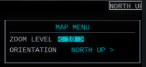
The zoom level shows a choice of distances, the distances are the range of the map from the bottom to the top of the MFD screen. They depend of the latitude of the aircraft.
Four orientations are available:
NORTH UP: in this configuration the aircraft symbol rotates, the map is aligned with North upTRK UP(Track Up): if aircraft is on the ground the aircraft symbol doesn't rotates and is up, map rotates to represent the heading of the airplane. Airborn, the top of the map is aligned with the current ground track.DTK UP(Desired Track Up): alignes the map with the desired course (only available if desired course has been set)HDG UP(Heading Up): the top of the map is the current heading of the aircraft
When the desired zoom and orientation are selected, validate by pressing ENT button. Pressing the CLR exit the modification window without saving the changes.
Terrain
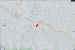
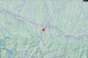
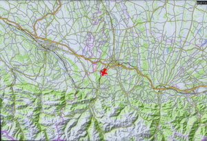
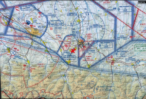
You have to choose the map background you want to be displayed. For this you have to use the options in your .fgfsrc. This is subject to change in near future in order to allow to change the maps while the device is running. For now there are some options to tells the zkv1000 which map you want:
- without any configuration (default settings), tiles from wikimedia.org
- If some more information are needed in URL (as registration key) you may want to use the
/sim/online-tiles-apikeyproperty
--prop:/sim/online-tiles-server=tile.thunderforest.com
--prop:/sim/online-tiles-type=landscape
--prop:/sim/online-tiles-apikey=?apikey=XXXXXXXXXXXXXXXXXXXXXXXXXXXXXX
- If there is no specific "type", please affect
/char to property/sim/online-tiles-type
--prop:/sim/online-tiles-server=a.tile.opentopomap.org
--prop:/sim/online-tiles-type=/
- If the URL can't be easily standardized, you can create you own template with property
/sim/online-tiles-template, you can use some tags from properties as{server},{type}and{format}, where values come from respectively/sim/online-tiles-server,/sim/online-tiles-typeand/sim/online-tiles-format:
(maps covering only France)
--prop:/sim/online-tiles-server=wxs.ign.fr
--prop:/sim/online-tiles-type=GEOGRAPHICALGRIDSYSTEMS.MAPS.SCAN-OACI
--prop:/sim/online-tiles-format=jpeg
--prop:/sim/online-tiles-template=https://{server}/an7nvfzojv5wa96dsga5nk8w/geoportail/wmts?layer={type}&style=normal&tilematrixset=PM&Service=WMTS&Request=GetTile&Version=1.0.
- By default, protocol is
https, so if you needhttpyou'll need to use/sim/online-tiles-template
(The follwing example doesn't display anything, tiles are empty around LFBT, need to investigate a bit)
--prop:/sim/online-tiles-server=1.tile.maps.openaip.net
--prop:/sim/online-tiles-type=EPSG:900913@png
--prop:/sim/online-tiles-template=http://{server}/geowebcache/service/tms/1.0.0/openaip_basemap@{type}/{z}/{x}/{y}.png
(screenshots to come as soon as the highlighting system will be repaired) By default the navaids around the aircraft are shown on the map (airports, VOR & TACAN, NDB)
(screenshots to come as soon as the highlighting system will be repaired)
By turning the MFD Outer FMS knob you enter in menu system, turn the Outer FMS knob to select the NRST page. The available nearest navaids searches are in light-blue chars, the grey entries aren't available for now.
As the day of writing, here are the available searches:
- NEAREST AIRPORTS
- NEAREST INTERSECTIONS
- NEAREST NDB
- NEAREST VOR
Select the desired search by turning the Inner FMS knob, and validate your choice by pressing the ENT button. The navaids available in a range of 100NM are listed, one by line, the second line contains the distance and course from the aircraft to the navaids. You can select by turning the Inner FMS knob and validate your choice by pressing the ENT button.
You can have information about the selected navaid by pressing the ENT button. For radios navaids it include frequencies, coordinates, complete name, eventually range if the data is available. For airports the information include name, coordinates, frequencies, runways (eventually with ILS frequencies)
In near future it will be possible to compute a DTO, or include the navaid in an existing flightplan, but for now these features aren't yet released...
The scrolling feature isn't really well managed, and there are some nasty things displayed, but a go-to-bottom then go-up correct it in most of the cases
Route
TCAS
Traffic announciator is shown as there is a traffic in sight, until there is no traffic at all
Topography
Inset map
Menus
Set screen brightness and body lighting
(screenshots to come one as soon as the highlighting system has been repaired)
On PFD without other windows opened, click on MENU key in order to make the System Settings windows displayed. You can use Inner FMS knob to adjust the brightness of the screen percent by percent from 0% which is very low, to 100% which is adapted to very shiny conditions.
During night, you can also make the ZKV1000 body being lighted (keys, softkeys and knobs descriptions). To do so, select the Light using Outer FMS knob, and adjust the lighting with the INner FMS knob. There are four level, from 0 which is light off, to 3 which is very luminous. Adjust to the level you are the most comfortable.
Using MENU or CLR key close the window.
The settings aren't stored for future flight sessions
Checklists
(screenshots to come as soon as the highlighting system will be repaired)
If the aircraft provides checklists, they can be visualized directly on the MFD.
To show checklists, press the softkey CHKLIST (which is available only if aircraft has at least one checklist). The checklists are divided into two groups:
- emergency checklists
- all the others
The emergency checklists are accessible by pressing the EMERGCY softkey. This will present a list of checklist if there are multiple checklists, or directly the emergency playlist if there is only one.
The other checklists may be divided by groups of checklists, in this case the group are shown then you can select using Inner or Outer FMS knob the desired group of chekclists, valid your choice by pressing the ENT button. Then another list will be displayed then you can select the desired checklist with Outer or Inner FMS knob, and valid your choice by pressing the ENT button. If there is no groups of checklists, the list of available non-emergency checklists are displayed. Select by using Inner or Outer FMS knob, and valid your choice by pressing ENT button.
A checklist may have more than one page, to navigate into the pages select NEXT or PREVIOUS and validate by pressing ENT button.
To exit a checklist, or selection of checklist, just press the CLR button.
