TerraGear support for Draping
| Work in progress This article or section will be worked on in the upcoming hours or days. Note: This page features a currently unreleased feature. See history for the latest developments. |
What is Draping
| Note
See also Photo scenery.
See also Canvas_Development#Scenery_Overlays.
|
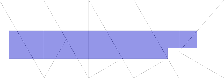
Draping is placing a 2-dimensional object over a 3 dimensional one. The 2 dimensional object will take the shape of the object beneath.
Potential uses in Flightgear
- Airports - imagine no more edge matching between airport btg files and the terrain btg files. If the terrain were to ever change level of detail, matching the edges again could be very messy. If the airport were draped over the terrain, the terrain could be modified by LOD algorithms, then the airport would re-drape over the new terrain. Currently, linear features use a VERY crude draping mechanism - and it really doesn't work so well. the taxiway marking sometimes float above - or disappear underneath the pavement. We are using the same height function for each vertex to calculate the height, but this isn't really draping.
- OSM data - we could have the ability to turn on / off the display of complex road / railroad / stream data at runtime, or based on LOD. Since the vector data would drape over existing terrain instead of cutting into it.
- landclass transitions - instead of complex shading algorithms, how about draping a transition poly over the transition area. For example, an urban transition polygon could be placed on top of neighboring grassland. the texture could periodically 'alpha channel' out some city blocks - leading to a much more realistic transition.
How would it work
1) tgconstruct would create the terrain BTG as usual, but without holes for airports - the apt.dat file would only be used to generate the airport boundaries. Within these boundaries, The same smoothing algorithm would produce the airport surface within the terrain btg (using whatever landclass is defined for the area, so airports with lakes within the boundary would now be possible)
2) tgconstruct will also not cut vector data into the terrain (we'll have to specify vector based polys from landclass based). It would generate a file similar to .btg (or maybe within the btg, under a new header) with 2d data only. This data is almost raw (ie, not triangulated, but it would be clipped)
3) SimGear would display the btg terrain, then drape the 2d shapes over it. This would proabably be in yet another thread? I haven't done performance testing yet, but I'm hopeful that it can be pretty fast.
How would SimGear perform the drape operation
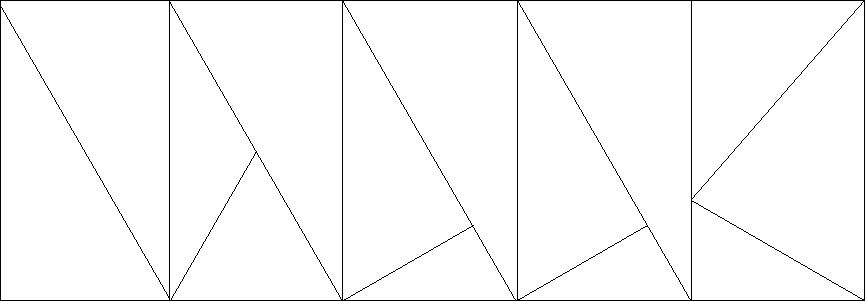
1) First, simgear loads the underlying terrain - this has already been triangulated by construct. It can choose to drape polygons on top of it or not based on LOD settings.
2) A draped polygon is loaded (from either .BTG or a new TBD file - only 2D Geodetic vertices - altitude above sea level not computed yet)
3) The polygon vertex height data needs to be calculated based on the triangulated mesh.
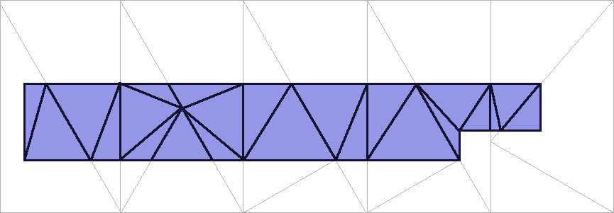
- A CGAL arrangement (either the whole tile, or within the draped polygons bounding box) is constructed.
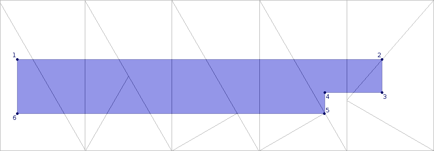
- The position is looked up - the result may be a face, line segment, or vertex.
- 1, 3, 4, and 6 would be face results - height is found by intersection of a line paralell to the up normal, and a plane defined by the faces 3 vertices.
- 2 would be line segment result - height is found by interpolation.
- 5 would be vertex result - height is found directly from the vertex height.
- TODO: The normals also need to be calculated
4) the underlying mesh needs to create new vertices in the polygon.
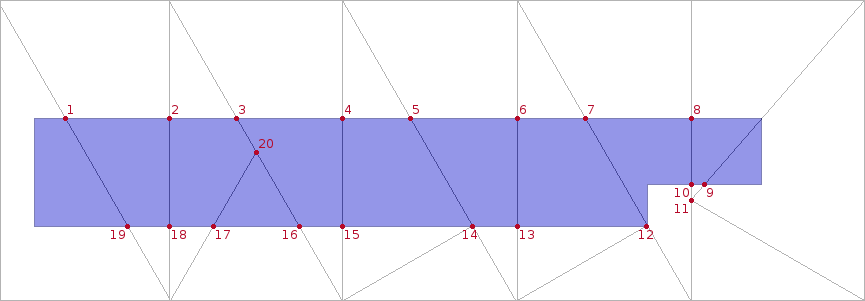
- the same CGAL arrangment is use to calculate intersection points from the polygons line segments.
- Intersections may line on the arrangement's line segments or vertices.
- 1, 2, 3, 4, 5, 6, 7, 8, 9, 10, 13, 15, 16, 17, 18, and 19 all intersect line segments - height is found by interpolation.
- 12 and 14 intersect vertices - height is found directly from the vertex height
- 11 12, 14 and 20 are nodes in the arrangement that are with in polygons bounding box. These will need to be passed to triangulation. Height data is found directly from the vertex height. Note: vertex 11 will not be returned in the triangulation result, and is discarded
5) After triangulation, all of the generated verticies of the draped polygon are colinear with the underlying terrain. polygon ffset can be used to prevent z-fighting.
