Radio propagation
 | |
| Started in | 12/2011 |
|---|---|
| Description | Enabling real time realistic radio calculations depending on terrain, landcover, transmitter station, receivers station. Everything configurable via the property tree. Using Flightgear as a general purpose, 3D, radio signal propagation and terrain analysis tool. |
| Maintainer(s) | Adrian |
| Contributor(s) | User:Adrian (since 09/2011), |
| Status | Under active development as of 08/2013(project is separated from mainline source) |
| Folders | $FG_SRC/Radio |
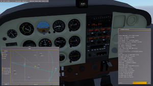
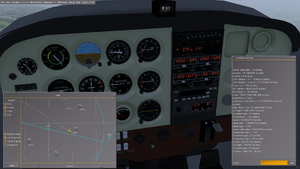
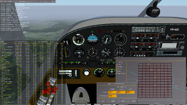
This article describes an effort to implement a realistic radio propagation model inside FlightGear. For various reasons it was not integrated into FlightGear, but this page is kept as the subject comes up now and then.
Summary
The code and algorithms described below enable the following features in FlightGear, which to the author's knowledge are unique for a conventional flight simulator:
- Realistic radio reception of ATC and AI aircraft messages.
- Realistic radio reception of VOR stations, making radio navigation more interesting and realistic in hilly/mountainous terrain.
- Realistic range for DME equipment, reception is now very different to VOR signals due to the very high frequency used. You could have full deflection on the NAV display and no DME data until you pass a minor obstruction.
- Realistic reception of TACAN stations, including mobile stations (AI tankers etc.). Conditions similar to DME.
- Mostly realistic radio reception of localizer and glideslope signals, making landings more interesting for certain airports.
- Configuration and realistic reception of radio beacons located anywhere in the 3D world, while presenting calculated signal values according to different official guidelines, including but not limited to the FAA.
Roadmap
We are currently looking into updating the code base, to ensure that things still work with FG 3.0+
Using FlightGear as a general purpose, 3D, radio signal propagation and terrain analysis tool
The purpose of this document is to evaluate the possible usage of the FlightGear engine as a tool for RF signal loss prediction over a rough terrain, using geographical features embedded inside terrain data and well know propagation prediction algorithms.
There are currently a number of freeware and open source applications that perform RF signal loss analysis using data available to the general public (elevation data, landcover etc.).
Well known and used are Radiomobile,[1] a Windows application by Roger Coudé, VE2DBE and Splat![2] (multiple platform) by John A. Magliacane, KD2BD.
A common point of these applications is the usage of the Irregular Terrain Model (ITM, also known as Longley-Rice)[3] which is a propagation model developed by the U.S. Department of Commerce NTIA/ITS - Institute for Telecommunication Sciences and improved by several others (notably ITWOM[4] by Sidney E. Shumate, code available to the public on a limited usage license, copyright Givens-Bell[5]).
It is a general purpose model that can be applied to a large variety of engineering problems. The model, which is based on electromagnetic theory and on statistical analysis of both terrain features and radio measurements, predicts the median attenuation of a radio signal as a function of distance and the variability of the signal in time and in space.[6][7] It is currently used among others by NASA, Alcatel-Lucent, US Army, University of Massachusetts and amateur radio operators around the world, and is widely considered the best propagation model for frequencies between 50 - 5000 Mhz freely available to the public.
One of the most active users of the Irregular Terrain Model is the US FCC (Federal Communications Commission), which is currently applying the updated version of this model for broadcast station regulations.[8]
Rationale
The implementation of radio propagation analysis is mostly finished inside FlightGear. Since the terrain used by this open-source flight simulator contains both elevation information and landcover data, it seems especially suited for a 3D tool to predict RF signal levels, both for aviation navigational aids and radio communications, and standalone as a point-to-point radio link analysis between two radio stations.
FlightGear allows the user to place models on the terrain at specific locations, and to setup internal properties via a simple XML format.
Rather complex radio receivers and transmitters can be simulated using the Nasal scripting language or via an external utility, as well as an UI to perform signal level reading and modify receiver and transmitter physical characteristics. The 3D aspect is also interesting, since it allows one to perform predicted signal level reading at different locations while inside the simulator, using visual cues to place the radio equipment on the terrain.
Since this open-source flight simulator is capable of running on multiple platforms, including GNU/Linux, Microsoft Windows and MacOS, its availability is not limited to one operating system.
Data
Most of new generation FlightGear terrain uses NASA SRTM v3[9] elevation data, which has a distance of 90 meters between elevation points. This is considered accurate enough for most signal analysis, although more detailed elevation data from topographical maps, ASTER DEM or other sources can be acquired. Default landcover in FlightGear comes from VMAP0[10] layers, with more accurate geodata being available from national and international programs, such as Europe's flagship program, the CLC2006 "Corine" landcover project.[11]
Landcover data is used to analyze path loss and improve predicted signal levels over specific types of terrain, but should be cross-checked with real-world RF signal readings took at the same locations.
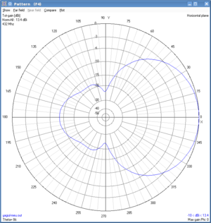
Antenna radiation patterns obtained using the free tool NEC2x can be used for both transmitters and receivers. Patterns obtained from other applications can be used too, as long as they are converted to the rather simple text format which is used by the FlightGear radio code.
Also, data from FlightGear's realistic atmospheric and weather simulation could be taken into account when path loss analysis is performed.
Request for information
If you are involved with maintenance or have detailed information about navaid transmitter capabilities, the author would appreciate if you listed in the discussion page the following information:
- Usual transmitter power for localizer (known to be between 15-25 W) and glideslope (known to be between 5-10 W ???) equipment.
- Usual transmitter power for DME (not VOR) equipment: Various source suggest from 50 W to 1 kW (I guess these values are ERP, since reported antenna gains are 8 dBi on vertical polarization).[12]
- Usual receiver sensitivity (in dBm) for DME equipment (-95 dBm taken from source).
- Usual antenna types and gains for localizer and glideslope equipment: For localizer the ERP (effective radiated power) is known from various sources as approx 100 W, thus assuming 7-9 dBi antenna gain, glideslope antenna estimated gain 10 dBi.[13]
- Most sources describe a 16 dB front-to-back ratio, thus being consistent with the default pattern used and shown in the picture above. Corrections welcome.
- Usual localizer/glideslope/DME antenna types and gains for various aircraft, for usage by aircraft developers (most sources show V-type dipole).
Implementation details
In order to use the point-to-point routine of the Longley-Rice model, a terrain profile between the two radio stations is generated by sampling the terrain with a configurable distance between points (default is 90 meters, which is equal to SRTM 3 arc sececond precision). This terrain profile is fed to the ITM routines, together with some other parameters: Transmitter output power, receiver sensitivity, antenna heights above terrain. These routines are the core of the implementation, and incorporate improvements made by J. D. McDonald, John A. Magliacane and Holger Schurig to the original code.
The result is signal attenuation in dB along the direct path. The ITM functions will determine for us if the radio propagation is line-of-sight, diffraction dominant or tropospheric scatter. For diffraction propagation, it also determines if it's single horizon or double horizon.
This information will further be used in calculating ground clutter obstruction for different terrain types. The most frequent obstructions that affect radio signals are built-up areas and tall vegetation. By calculating the interference of ground clutter inside the first Fresnel zone, we can determine signal losses with average precision.
In order to do so, we need two more numbers in the equations: Clutter height above terrain, and clutter density. These are stored inside a plain text file located inside the Materials/ directory, allowing for more terrain types to be added and properties to be changed by the user. The aim is to make these two factors as configurable as possible to the user, in order to be able to adapt them to local measured conditions.
The radio stations parameters are also completely configurable by the user, by setting internal properties, via Nasal scripting or otherwise.
For ATC comms, at the current state, some basic assumptions are made about transmitter power, receiver sensitivity and antenna heights: These are based on standard ATC interactions, but this will be changed in the future to support a wider variety of signals. It might even be possible to simulate realistic ACARS transmissions, as well as transponder responses with realistic range and signal quality (introduce errors based on signal quality etc.)
Usage
To enable the radio code, use the following command line flags:
--prop:/sim/radio/use-radio=true
- Enables the main radio code
--prop:/sim/radio/use-clutter-attenuation=true
- Enables the ground clutter attenuation calculations
--prop:/sim/radio/use-antenna-pattern=true
- Enables the antenna radiation patterns
--prop:/sim/radio/itm-radio-performance=false
- Disables performance mode (useful for propagation study)
--prop:/sim/radio/material-radio-database=true
- Use the SQLite database for landcover types and radio properties. It is named
material_radio_properties.sqliteand placed in$FGROOT
--prop:/sim/radio/sampling-distance=90
- Distance between terrain profile points. Defaults to 90 meters which is the accuracy of SRTM elevation grids. A smaller value coupled with disabling performance mode will have an impact on the performance and will only be useful in very high resolution terrain. Use a larger value to relieve performance issues.
Known limitations
- The loading distance of terrain. For stations which are beyond the maximum configured terrain loading distance, path profiles will not be accurate and some errors are likely to occur in the signal loss figures. The experimental terrain sampler based on an elevation database attempts to get rid of tile loading distance as a factor in this. It is a work in progress though, while reliable it needs a separate tool set to generate the database. To be used only for very special purposes (ground radar?).
- The current model does not take into account signal reflection from objects or terrain features, nor refraction caused by atmospheric conditions.
- The diffraction calculations within the ITM library are not very precise and are likely to overestimate losses caused by diffraction over a sharp edge, or when take-off angles are beyond a certain limit. This has been corrected in the new ITWOM, which is available to the public with commercial restrictions.[14]
- Clutter loss calculation are only estimative and should only be taken into account after careful calibration done with measurement equipment at the sites.
Currently implemented features within the FlightGear engine
- The code has been transitioned to a more efficient and performance-friendly subsystem structure
- Point-to-point path loss calculations over rough terrain using the ITM library for air traffic control stations to pilot communication. Also AI to pilot reception.
- Point-to-point path loss calculations using the ITM library for VOR/localizer and glideslope stations.[15]
- Point-to-point path loss calculations using the ITM library for DME stations.[16] Can be affected by some issues with stations sunk in the ground (request test info).
- Point-to-point path loss calculations using the ITM library for TACAN stations, including mobile stations (AI tankers etc.).[17] Can be affected by some issues with stations sunk in the ground (test info is requested).
- For VHF/UHF stations beyond a reasonable terrain loading distance, automatic transition to path loss calculation over a smooth round earth using alternative free space signal attenuation equations
- RF link budget calculations using transmitter power, receiver sensitivity, antenna gain and height above terrain, taking into account typical values from various specifications
- Experimental feature: Usage of detailed landcover in RF propagation prediction (ground clutter path loss)
- Landcover radio properties are stored into an easy to read and modify
.txtfile in theMaterials/directory, allowing for more terrain types and radio properties to be changed by the user - Signal loss due to polarization mismatch
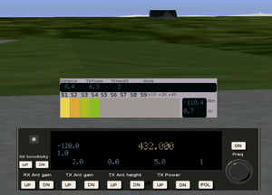
- Simple signal strength indicator (Instrument for signal level reading)
- Far-field antenna radiation patterns generated with 4nec2
- Radio transmitter beacons can be placed with the model tool inside 3D space, models placed with the UFO tool will use a separate tree to avoid conflicts with other types of models (weather, etc). In the future it will be possible to define and change properties for multiple beacons from the same panel instrument.
- Using the property tree, a radio station can be defined with Nasal scripts
- Support for multiple radio stations running at the same time: Navaids, ATC comms, beacons
- Efficiency mode: The number of terrain data points decrease proportionally with the distance to the station.
- Calculation of electrical field strength in μV/m, received signal strength in μV and dBm, as required by official guidelines.
Features which still need to be implemented
- Figure out what to do about VOR/DME/TAC stations sunk into the ground? Possible bug affecting them, maybe only on custom terrain.
- Reception of ACARS ground messages via VHF radios
- Usage of weather simulation and atmospheric conditions which affect radio propagation: Tropospheric ducting, cloud backscatter etc.
- Simulate realistic transponder response
- Realistic ground-to-air radar
- Reliable tool chain for generating data used with the alternative terrain sampler.
Qt GUI control
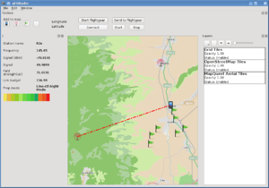
- A Qt-based GUI with OSM map controls and satellite imagery is available to control all aspects of FlightGear's RF planning features. See the main article, QRadioPredict
Mailing list discussions
- http://www.mail-archive.com/flightgear-devel@lists.sourceforge.net/msg33688.html
- http://www.mail-archive.com/flightgear-devel@lists.sourceforge.net/msg34983.html
- http://www.mail-archive.com/flightgear-devel@lists.sourceforge.net/msg35010.html
- http://www.mail-archive.com/flightgear-devel@lists.sourceforge.net/msg35921.html
- http://www.mail-archive.com/flightgear-devel@lists.sourceforge.net/msg38839.html
- http://www.mail-archive.com/flightgear-devel@lists.sourceforge.net/msg38901.html
