Howto:Convert from AC3D to glTF
This guide is targeted at aircraft developers wanting to get started converting AC3D models to glTF models supporting PBR/HDR and suitable for 2024.2.
Caveat: The author is not an aircraft developers, and this guide will focus only on the main processes involved. It also assumes use of Blender 4.5.3 LTS. We are using as an example Emmanuel Baranger's Stampe-SV4 as a simple aircraft but with nice animations and materials. Thanks Emmanuel!
Importing AC3D to Blender
See Howto:Work with AC3D files in Blender. For Blender 4.5.3 on Linux I had to install the importer to $HOME/.config/blender/4.5/extensions/user_default/.
By default, the .ac file will be imported with a "Principled BSDF" surface, and can be exported out as .glTF. See GlTF for details of the export settings to use.
XML Changes
Obviously you need to change the model.xml file to reference the .glTF file rather than .ac.
You should also take the opportunity to set the appropriate -set.xml files entries.
Specifically, under <sim>.
<minimum-fg-version>2024.2.0</minimum-fg-version>
and
<compatibility>
  <pbr-model>true</pbr-model>
</compatibility>
This will ensure that the aircraft is displayed correctly within the launcher.
Animations
Unfortunately the axis for animations are different between .ac and .glTF. You may need to swap the Y and Z axis, and reverse the Z axis.
This is easiest seen by an example, and is fairly easy to do semi-mechanically by going through an animation file. Fortunately the X (forward/backwards) axis is unchanged, so more steam gauges should work unchanged.
Example: Aileron rotation using two sets of points:
2024.1.3
<animation>
  <type>rotate</type>
  <object-name>aileronBD</object-name>
  <property>surface-positions/right-aileron-pos-norm</property>
  <factor>-15</factor>
  <axis>
    <x1-m> -0.393 </x1-m>
    <y1-m>  3.357 </y1-m>
    <z1-m> -0.304 </z1-m>
    <x2-m> -0.698 </x2-m>
    <y2-m>  1.186 </y2-m>
    <z2-m> -0.383 </z2-m>
  </axis>
</animation>
2024.2.0
<animation>
  <type>rotate</type>
  <object-name>aileronBD</object-name>
  <property>surface-positions/right-aileron-pos-norm</property>
  <factor>-15</factor>
  <axis>
    <x1-m> -0.393 </x1-m>
    <y1-m> -0.304 </y1-m>
    <z1-m> -3.357 </z1-m>
    <x2-m> -0.698 </x2-m>
    <y2-m> -0.383 </y2-m>
    <z2-m> -1.186 </z2-m>
  </axis>
</animation>
Effects
glTF by default has what's known as a "Principled BSDF" surface model [1]
FlightGear will automatically assign the model-pbr Effect to glTF files, which should be used unchanged by aircraft. If you find yourself wanting to add an effect, talk to the core team - it may make more sense to enhance the model-pbr effect.
The only Effect that should be applied direclty is model-transparent-pbr Effect which should be used for transparent objects.
Textures
PBR uses a set of properties of materials to render surfaces with much greater accuracy than previous rendering methods. As such, the use of textures is somewhat different.
The main texture is purely used for the base colour of the material, unlike in 2024.1, where it might also include an ambient occlusion texture and emulate roughness and the sheen of metallic materials.
Principled BSDF can take Metallic and Roughness values direct from the Material entry in Blender. However this generates lots of materials, which is undesirable from a performance perspective. glTF (and the model-pbr effect) supports using an additional texture which has (Ambient) Occlusion, Roughness and Metallic information in the RGB channels. This allows you to adjust the roughness and metallic values in the texture itself - for example to mimic polished areas of surfaces. It also allows much more naturalistic rendering of occlusion.
Ambient Occlusion (AO)
Blender can render a texture for ambient occlusion (See "Bake" under the Editor properties). Unfortunately, it will bake to a grayscale texture, when what we require is the occlusion information written to the red channel of the ORM texture.
Additionally, Blender support for Ambient Occlusion in glTF is a bit of hack on Blender's part, and you need to create a special node for it to be exported properly. See https://docs.blender.org/manual/en/latest/addons/import_export/scene_gltf2.html.
Putting together the ORM texture
The ORM texture uses channels for different information:
- Red - Ambient Occlusion
- Green - Roughness (0 = smooth, 1 = rough)
- Blue - Metallic (0 = non metallic, 1 = metallic)
You can use an image editor such as GIMP, or the UCUPaint extension for Blender which allows in-Blender painting of material properties.
GIMP
Using GIMP, the easiest way to manage this is to have separate layers for each channel:
- Open the Baked AO texture from Blender
- Make only the Red channel visible
- Use Layer -> New from Visible to create a layer containing only Red information. Label this "Occlusion - R" so you don't forget
- Create two layers above this. Under Layer Attributes change the mode to "Addition", and label them "Roughness - G" and "Metallic - B" respectively
- Delete the bottom later which contains the grayscale AO texture.
You should now have 3 layers, one with a red image of the AO, and two layers with no information.
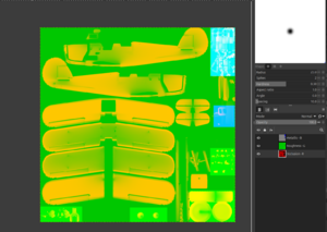
Using your texture guide, work out (or guess) the roughness and metallic values for the various areas, editing the appropriate layer only, and ensuring you only add colours of that channel - e.g. ensure that "R" and "G" are set to 0.0 when working on the metallic (B) channel. See the example image which has some high metallic surfaces (top left blue and cyan), some rougher surfaces towards the bottom (light green) and various ambient occlusion textures (seen as the ghostly outline of the wings and fuselage with darker areas where the wings meet the fuselage).
Save the texture as a .xcf as you work, as the final baked .png texture will combine the channels.
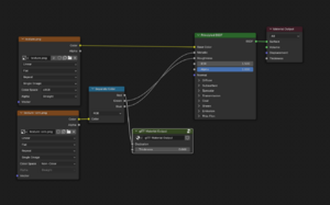
Once you are happy with your texture, reload it into Blender, and link it into the Principled BSDF shader as shown in the diagram above.
Not Using a Texture
As of end of 2025 not using a texture leads to rendering problems in FlightGear Next, which gives either a very blurry/not sharp edges look (when there is no materials definition) or broken looks (e.g. like shattered glass). If you want good results, you have to use texturing. If you do not want to texture the objects, then you are better off continuing to use *.ac files exported from Blender with a material definition than *.gltf files exported from Blender with or without assigned materials.

