Fr/créer des scènes dans FlightGear
![]() FlightGear Scenery Designer (Concepteur de scènes FlightGear) ( aka fgsd ) est un outil pour créer et dessiner des scènes en tuiles sur mesure, adaptables à FlightGear. Il a une fonction similaire à TerraGear, mais d'une manière différente. TerraGear est dédié à la réalisation automatique d'un grand nombre de fichiers, et ainsi, il est employé à produire les scènes globales distribuées avec FlightGear et via TerraSync; fgsd vise une plus petite échelle, pour réglage fin de de quelques tuiles par l'intermédiaire d'une interface graphique.
FlightGear Scenery Designer (Concepteur de scènes FlightGear) ( aka fgsd ) est un outil pour créer et dessiner des scènes en tuiles sur mesure, adaptables à FlightGear. Il a une fonction similaire à TerraGear, mais d'une manière différente. TerraGear est dédié à la réalisation automatique d'un grand nombre de fichiers, et ainsi, il est employé à produire les scènes globales distribuées avec FlightGear et via TerraSync; fgsd vise une plus petite échelle, pour réglage fin de de quelques tuiles par l'intermédiaire d'une interface graphique.
A partir de Mars 2011, il ne semble pas que fgsd soit développé activement.
Pour une autre approche de ce grand challenge de décoration du monde, voir le World Custom Scenery Project.
Documentation
La Documentation pour fgsd est mince et dure à trouver. En dehors de cette page de Wiki, vous pouvez trouver l'aide suivante:
- Howto: Faire un aéroport
- La page de documentation du [fgsd http://fgsd.sourceforge.net/ Sourceforge] website. Elle comprend une video tutorial/demonstration en quatre parties (pas de son) illustrant les nombreuses étapes de l'utilisation de fgsd, et les instructions pour placer les objets statiques (static objects).
* Le FlightGear Forum, dans la section Scevery. Ceci paraît être la source la plus courante, mais elle est difficile à trouver.
Si vous trouvez des sources plus détaillées, ajoutez les ici pour qu'elles soient plus faciles à trouver.
Histoire et Philosophie
Comment travaille fgsd et quels sont ses fils conducteurs![]()
The initial purpose of fgsd was to edit existing scenery because of the lack, at that time, of a decent free elevation model outside the USA. Releases up to 0.3.1 had capabilities to hand-edit part of the terrain. But it appeared to be cumbersome to edit triangles one at a time, and very frustrating as the work done on one tile was obsoleted every time a new global scenery was released. Moreover, editing the result of the TerraGear process proved to be non-trivial because of hidden gotchas on the topological quality of the tiles.
Finally, NASA and others released the SRTM digital elevation model that offers a more refined elevation dataset for most of the world, lessening the need to edit elevations manually.
From release 0.4.0 ( to be released ) ( and its pre-releases 0.3.9x - Win32 binaries available here - Other systems, use CVS ), fgsd no longer offers the ability to edit already made scenery tiles. Instead, it works interactively, using the same workflow as TerraGear. This workflow can be summarized as follow :
- load raw elevations
- simplify elevation model
- prepare land cover contour
- project land cover contour on terrain
- prepare airport layout
- project airport layout on terrain
- export terrain to fgfs scenery tiles
additionally, 3D object models can be placed here and there to add verticality to this somewhat horizontal world.
One side benefit of this approach is that modified land cover contours can be exported to a format that TerraGear can use. A centralized database of contours is setup for that ( see http://www.custom-scenery.org ). This way collaborative changes to the global scenery can be consolidated and the next round of global scenery generation will include submitted individual changes. Of course, import from the landcover database is possible in fgsd.
Airports are loaded from the airport database file located in the FlightGear base package. It is not possible to edit an airport, but a new definition of an individual airport can be loaded from a file in X-Plane format. This kind of file are typically produced by the Taxidraw airport editor.
What you need to run fgsd
PLEASE ADD TO THIS LIST OTHER PLACES WHERE THESE THINGS CAN BE FOUND.
- fgsd itself.
- Source code from SourceForge
- Windows binaries available here
- Elevation data from the SRTM (Shuttle Radio Topography Mission), in .hgt file format, at either SRTM-3 or SRTM-1 resolution. Please note that if you want your work to eventually be incorporated back into FlightGear, you have to be careful to use elevation data sets that are compatible with the GNU Public License, such as the original SRTM data issued by NASA.
- Surface landuse data from the FlightGear Mapserver
- Aerial photographs that are keyed to latitude and longitude
Main window
Menu
File
- New
- Clears the current work area ready for a new project.
- Open
- Project
- Opens an existing project file.
- Tile
- Opens an existing tile. This is mainly used to place static objects. Editing a tile is not supported anymore.
- File
- Opens an existing file. It can be an elevation file or a fragment file. Elevation files contain raw elevation data and provide the basis for a project.
- Recent Files
- Opens recently opened files. These may be tiles or elevation files.
- Recent Projects
- FGSD saves work in *.FGSD files. These files contain references to map fragments as well as any land cover that might have been added. Various other pieces of information regarding the environment used to create that work are also saved.
- Save Project
- Saves the current environment. If the project has already been given a name, that names is used to save the work, otherwise you will be prompted to provide a new name
- Save Project As
- Saves the current environment under name that is prompted for.
- Export
- Exports the project to tile format. The results of the export process may be used in FGFS to view the progress of a project.
- Quit
- Exits FGSD
- Project
Edit
- Undo
- Undo last action
- Redo
- Redo last undone action
Scenery
- Simplify Terrain
- Strip Raw Elevations
- Embed Curves
- Embed Airports
Tools
- Object Library
- Displays the Object library window
- Map Fragments
- Displays the Map fragment window
- Import Curves
- Select Airports
- Chop HGT Files
- Options
- Displays the Options window
Toolbars
Main toolbar
Curves toolbar
Scenery toolbar
Static objects toolbar
Airports toolbar
Main area
Status bar
Options window
How to set general options and preferences
This window has 4 tabs :
- General
- Flightgear
- LandcoverDB
- View
All parameters are saved in an XML file named ~/.fgsdrc
All path are in Unix convention : directories and names are separated by '/' ( slash ) character. Under Windows, the path may begin with :
General
- Output path
- this path will be used at export time. It can be overriden in the export window.
- Project history length
- number of project file names proposed in the File > Recent projects menu
- File history length
- number of file names proposed in the File > Recent files menu
- Display position in decimal
- choose the format of the longitude and latitude displayed in the status bar
FlightGear
- FlightGear data path
- the path to the FG_ROOT directory. This path is used to find the Airports/apt.dat.gz database, the materials.xml material database, and the Textures/ directory.
- FlightGear scenery path
- collection of path to scenery folders. These paths contain 'Terrain' and optionally 'Objects' subfolders. They are separated by ';' ( semi colon ) under Window, and by ':' ( colon ) under Unix.
LandcoverDB
- Shapefile directory
- a path to a local directory containing shapefiles representing landcover contours
- Database hostname
- a hostname to a Post-GIS server
- Layers
- list all .shp files discovered in the Shapefile directory and their assigned FlightGear area type. The 'Use' checkbox shows if the layer is used.
View
- Show constrained edges
- if checked, tile boundaries and material boundaries are drawn in red
- Show vertices
- if checked, terrain vertices are drawn with a blue square
- Show infinite edges
- ( used mainly for debug ) infinite edges are edges that connect the terrain hull vertices to an infinite vertex. They are shown in white.
Map fragment window
How to import images and georeference them
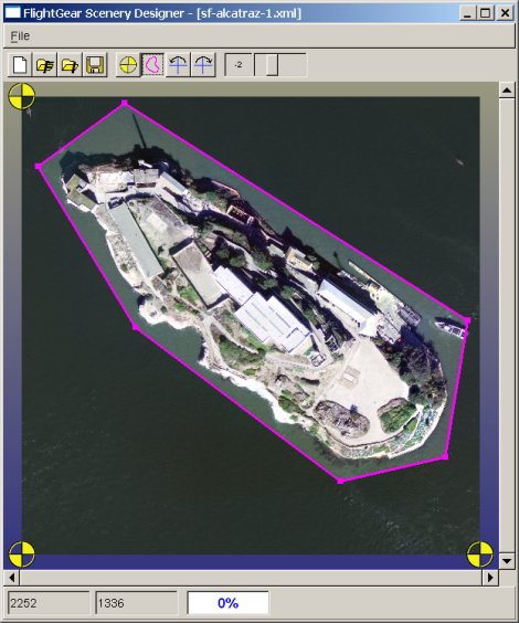
his window is used to georeference images before import in the main window. fgsd uses a 3 points method to correct rotation and non uniform scaling as well as positionning. A fragment have a contour that is initially set to the image extents. Only the image within the contour is displayed in the main window ( to discard ugly legend, for instance ).
The referencing information, as well as the contour and the image reference, are stored in an XML file.
Menu
The File menu has the items below :
- New
- erase the content of the window to start over.
- Open
- Fragment
- open an XML file containing the reference to the image, the contour and the referencing information
- Image
- open a JPEG file and set a default contour
- Fetch terraserver-usa.com
- load an aerial image from terraserver-usa.com, add a contour and georeference the image. terraserver-usa.com provides images from the USGS. These images are free to use.
- Save
- save the map fragment with the name it already has. If it is a new fragment, a name is asked first.
- Save as
- save the map fragment with a new name
- Close
- close the window. If the content is properly georeferenced, a popup is displayed to ask if the fragment should be included in the main window.
Toolbar
Icons, from left to right, are :
- New
- erase the content of the window to start over.
- Open Fragment
- open an XML file containing the reference to the image, the contour and the referencing information
- Open Image
- open a JPEG file and set a default contour
- Save
- save the map fragment with the name it already has. If it is a new fragment, a name is asked first.
- Marker mode
- Put the program in marker insertion mode. Every click in the image add a new marker at the mouse position and open a dialog box to position details
- Contour mode
- Put the program in Contour mode. The magenta contour is then editable. Contour nodes can be moved with the mouse, added or removed
- Rotate image 90 degrees counter-clockwise
- Rotate image 90 degrees clockwise
- Orient the image to correct disoriented scan
- Zoom slider
- Zoom in or zoom out by moving the slider cursor. Zooming in increase the positioning precision.
Marker mode
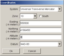
When the marker button is activated, every click in the image pops up the dialog box below :
Its purpose is to enter real world position of the click. This can be done in several ways, depending on the data available on the map/image being georeferenced. First one have to choose a coordinate system between :
- WGS-84
- Lambert I
- Lambert II
- Lambert II extended
- Lambert III
- Lambert IV
- OSGB 36
- Universal Transverse Mercator
The first one allows to enter position directly in degrees for longitude and latitude. The others need eastings and northings in meters.
Contour mode
This mode is used to move contour nodes, add new nodes or remove existing one.
Moving is done by dragging the node. To add a new node, first select an edge that should become cyan, and the CTRL-click where new point should be added. To remove an existing node, right-click on the node and select 'Remove point' in the context menu that pops up.
The contour should stay a non-intersecting loop, so the program controls that moves or modifications in the number of nodes are legal.
terraserver-usa.com images download window
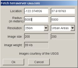
This dialog box is displayed when the 'Fetch terraserver-usa.com' is choosen from the file menu, or the 'Fetch terraserver-usa.com from here' popup menu option is choosen in the context menu of the main window. In the latter case, the location is the one under the mouse when choosing the option. Otherwise, this is the last location entered. The first location proposed is the one of KSFO, the San Francisco airport.
It allows one to connect to the server to get the aerial image centered at the location entered in the first line. The radius is the minimum distance between the center and an edge of the image, and can be a bit more due to the fact that image elements are 200x200 pixel square. Initially, the vertical 'radius' ( right field ) is set with the same value that is entered in the horizontal one. It is possible to change it to retrieve a non squared image.
There are 3 types of images available and several resolutions. An estimate of the size and the weight of the download is given before starting it.
During download, a progress bar is shown in the window status bar with a button to cancel the acquisition.
When acquisition is completed, markers are positioned at the image corners, and a contour is set around the image. It is then possible to save both image and fragment to files, and import them in the main project.
Object library window
How to organize 3D object models
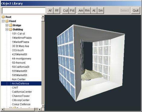
The Object library window is used to organize, display and select 3D object models.
The window has a tree of models and folders at its left. The right part displays in 3D the model selected in the tree. The top hosts a toolbar to manage the tree.
In the toolbar, the entry field at the left is used whenever a name is required by the subsequent button action. It must be pre-filled before one click on the button.
The Af button adds a new folder as a child of the current folder (initially, only Root exists ). The name is found in the entry field at the time of the click.
The Rf button renames the current folder. Again, the new name is the content of the field at the time of the click.
The Cut button removes the folder subtree or the model. It is left in a paste buffer and is not immediately destroyed.
The Pst' button pastes the content of the paste buffer as a child of the current folder.
The 'Am button adds a new model in the current folder. A file selection window is displayed and the user must select a model file supported by PLIB.
The Rm button is used to rename the model. The path remain unchanged
The At button is used to reference an additional file, for instance, a texture image file.
The Sm button stops or resumes model spinning in the 3D view.
The Select button is used when adding a static object in the scenery. It is grayed when the window is displayed from the menu.
The Quit is used to close the window. When a selection is prompted, this button cancel the selection.
It is possible to drag the mouse to change the camera position in the 3D view. Dragging with left mouse button rotates the model around its axis. Dragging the middle button rotates the camera around the model. Dragging vertically the right button change the distance between the camera and the model ( zoom ).
The object library is stored in an XML file named ~/.fgsdobjlib
Airport selection dialog
How to load airports and specify additional parameters
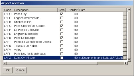
The airport selection dialog lists all the airport found in the database that can fit in the terrain loaded in the current project. If some of these are already loaded in the project, current parameters for them are displayed and reused. The dialog looks like :
The first column is the ICAO code.
The second is the name found in the apt.dat.gz file.
The third column ( titled 'Zero' ) tells if the labeling of runways with number less than ten takes a zero at the first place ( 09 vs 9 ).
The fourth column is the distance ( in meters ) between taxiways and runways and the airport boundary.
The fifth column is the path to an alternate description of the airport. The requested file must be in X-Plane format ( .dat file ). This is the kind of files can be created by TaxiDraw. The buttons pops a file selection dialog up.
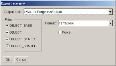
Export dialog
How to export the current project to files suitable for FlightGear
