FIAT G91R1B - Radio near selector
Introduction
Currently in flightgear there is no function to manage the frequencies used for navigation instruments (VOR, ILS, TACAN, NDB) during navigation. This fact makes it difficult for the pilot to manage this instrumentation as the simulator environment is very different from the real cockpit environment. It is obviously possible to make a flight plan and follow it, but the reporting of frequency data to the analog instrumentation is always quite inconvenient and uses a very different interface to that of the real plane.
For this reason, behind the solicitation of the pilots of the G91R1B in Flighgear, we have created this GUI which acts as a helper for the management of frequencies and radials.
The GUI has three different operating modes:
- Use the radios included in the flight plan.
- Scans the radios in the area with a criterion of proximity and angular distance, privileges the radios placed in the front part of the flight.
- In the vicinity of the airport, it provides ILS type radio assistance.
When the GUI intercepts a radio that can be useful for flying, it inserts the frequency and possibly the necessary radial.
If the proposed radial is not the one that interests the pilot, he can always modify it using the SET knob on the VOR instrument.
GUI operations
The GUI is activated from the FIAT G91 menu by clicking on the Radio near selector item. A window opens showing a series of blocks (tags) that define the functions that can be used by the pilot.
Activation tag
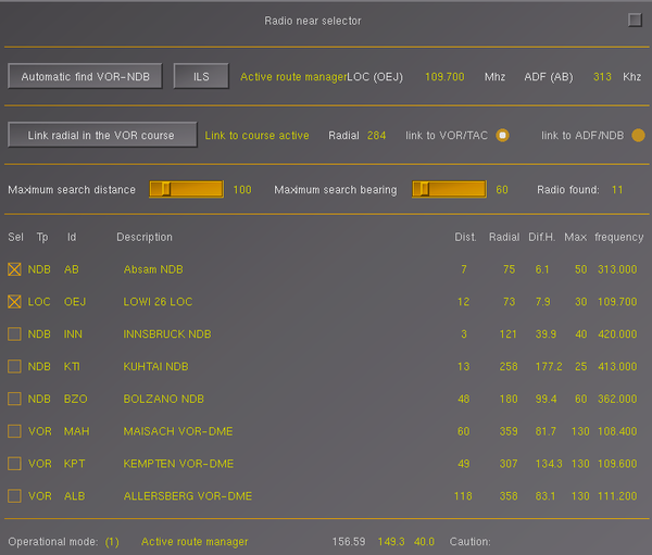
This tag allows you to activate the frequency acquisition functions. The first button Automatic find VOR-NDB is used to activate or deactivate the search for radio stations. The second ILS button activates the search by giving priority to ILS-type radios needed for instrument landing or take-off.
The following fields are used to report the selected situation. In the image Active search is a program status message, in this case it is active for the station search, the next field, in white, VOR (KEF) indicates the type and name (KFE) of the VOR type station ( or ILS or TACAN) with which you connected. The frequency is indicated by the yellow field 112,000 and is in Mhz. The white field ADF (KF) indicates the connected ADF radio and its name KF. Subsequently, in yellow, the frequency 392 and the unit of measurement Khz are indicated.
One note, when an ADF type receiver is connected, the program automatically activates the corresponding Marconi 8283 ADF radio receiver located on the console to the right of the pilot.
Link radial in the VOR course
The program can only show the frequencies and radials reachable by the aircraft radio equipment or link the radials (course) to the VOR or ADF equipment. In this example the VOR KEF (as seen in the previous tag) on radial 218 is active as reported by the Link to course active message. The link to VOR/TAC button indicates that the connection takes place on the VOR device, while the link to ADF/NDB button indicates that the link is established on the ADF / NDB apparatus. The importance of these two buttons is linked to the Pilot Assistant's Radial mode for managing the automatic heading, in this way it is possible to automatically direct the plane towards the radio station (VOR-TACAN or NDB), note then that when the station is passed vertically, the direction remains that indicated.
This option can be released simply by setting the radial of the VOR by turning the SET knob located to the left of the VOR. In this case, the message No link to course will be displayed.
Distance and bearing selector
As we will see in the following tag, the system can display up to 8 radio stations with a selection criterion that depends on the distance and the angle with respect to the flight direction of the aircraft (bearing). In this way it is possible to define a selection criterion compatible with the type of flight that the pilot wants to perform. The first slider Maximum search distance allows you to adjust the maximum selection distance, by default it is 100 nm, but it can go up to 400 nm. The second Maximum search bearing slider is the angle within which to select radio stations. The reference is the direction of flight of the aircraft, the angle is the one composed as the sum of the angle to the right and to the left of the flight direction. Therefore, in the example 80° means +/- 40° with respect to the course.
The last Radio found field is the number of Radio found, in this case 5, but it can also be higher than the number of radio stations displayed (maximum 8).
Ordered list of radios with automatic choice
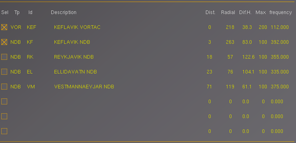
This tag shows an ordered list of up to 8 radios that meet the requirements of the filters defined above. The order is defined by a weighted criterion that combines the distance and the bearing angle. This way the radios shown above are probably the most useful for flying. Obviously it does not include radios that go beyond the maximum bearing angle, it is therefore necessary to make a turn to illuminate other radios that may possibly affect the pilot or widen, with the tag described above, the angle. However, the exit of the radios from the list, once they have entered, is not immediate, but remains for a certain time, this in order to avoid a continuous change of radios that could make it difficult for the pilot to understand the situation. This method allows you to define a search criteria in which it is possible to expand the view of the radios simply by increasing the search angle, but then reducing it as soon as the list becomes satisfactory for the pilot. The program automatically searches for the radios it deems most suitable for the flight phase and selects them with the check-box in the Sel column.
The Tp (type) column is the column that shows the type of radio described by the Flightgear radio database, Id is the identification id, further to the right is the Description column that shows the relevant field in the database.
The Dist (Distance) column shows the distance value in nm, the Radial column shows the radial in reference to geographic north, but the most interesting is the Dif.H. which shows the difference of the radial with respect to the route, which in this case, for the first row, is 36.3° therefore less than 40° (40 + 40 = 80°), while the others lines have a larger value, but are present because first we had taken the Maximum search bearing value to 360° (he made a sort of look around) to understand the context, as explained above. The following Max column indicates the theoretical maximum distance for the specific radio, but this distance can vary greatly depending on the altitude and altitude of the region in which the flight takes place. Therefore some radios may no longer be visible and to remember this problem, the Typ column will show, before the abbreviation, a character "!" (Radio no longer reachable). The last column Frequency reports the frequency of the radio always obtained from the system database.
Ordered list of radios with manual choice
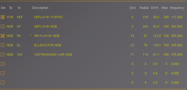
In Ordered list of radios tag it is possible to select the radios also manually, as well as automatically, the method is to click on the Sel check-box of the radio we want to select, in this case the radio will be fixed with the "manual choice" is displayed with a "*" character placed before the description.
The Sel check box has three states which are:
- not active
- activates automatically
- activates in manual mode
The third state is defined with the check box active and an asterisk placed before the description (third line in the image on the right). If you want to remove the manual option just click again the check box placed on the line with an asterisk. The asterisk disappears in a maximum time of 3 seconds (the time depends on the program refresh time which varies from one to three seconds depending on the operating context). If the manually selected radio is no longer reachable after a certain time (an exclamation point will appear next to the asterisk), after a certain time it disappears from the list anyway and the first equivalent active radio in the list will then be automatically selected.
Status line
They are a list of additional information not necessary for the use of the program, but useful for the knowledge of its actual state.
Operation mode reports the current operating context defined by the "mode" parameter (the value of the example is 2 so it means that the program is in automatic mode). The GUI has three different operating modes:
- Flight plan mode
Use the radios included in the flight plan. - Automatic scan mode
Scans the radios in the area with a criterion of proximity and angular distance, privileges the radios placed in the front part of the flight. - ILS scanning mode
In the vicinity of the airport, it provides ILS type radio assistance priority.
The mode is modified by the context, normally it is 2, but if a flight plan is active it becomes 1. Near the landing it can take the value of 3 (ILS) if the conditions allow it or it can be forced to this state by means of the ILS button placed in the first tag.
If the program is not active the mode is 0.
The next three numeric parameters are for debugging use and will be removed in the future.
The last field Caution defines any alert messages, in this case it reports that there is at least one line with "*" and therefore at least one radio has been selected manually and not automatically.
Operation together with the route manager
As already mentioned before, the Radio near selector application can work in conjunction with the system Route Manager it is sufficient that flight assistance radio is inserted between the points of the route manager. The program periodically (every 1 max 3 seconds) reads the list of selected route manager points and inserts the next radio and calculates the relative bearing according to what is reported by the route. If the route manager is deselected, the program automatically switches from mode 1 (Flight plan mode) to mode 2 (Automatic scan mode), if the router manager is reactivated the program returns to mode 1. If the router manager has undergone any changes, the program reinterprets them and follows the new course.
But the program also performs an auxiliary function that has proved essential under certain conditions. The program can automatically advance the router manager one step when its radio switches from front to rear. It is a particular situation that can happen when the pilot is very far off course (maximum 60 seconds, beyond it makes little sense), in this case almost always the route manager does not perform the automatic switch that instead does the Radio near selector to ensure the coherence of the flight. Remember that if the switch does not happen, you can use the mouse to select the next line of the route manager and click on the [Jump To] button. The Radio near selector, also in this case, automatically updates to the new flight pattern.
Operation together with the Pilot Assistant program e/o PHI system
The Pilot assistant allows to manage the flight automatically and therefore to interact with the PHI program, Route Manager and this Radio near selector. All these 4 programs, used together, allow to obtain a completely automatic flight similar to those that a good pilot can perform operationally. The simultaneous use of these programs can be a good way to understand how the various phases of flight occur and the appropriate use of navigation instruments. To do this we recommend following the following schedule:
- Activate a flight plan via the route manager. Enter the arrival airport as the last point of the route manager, in this way the Pilot Assistant will be able to know the airport and runway and then correctly activate the ILS mode (if active in that airport).
- Activate the Radio near selector with the [Automatic find VOR-NDB] button.
- Activate Pilot Assistant with the [Set activate] button at the top of the program, then when you see the message "Is partialy active" click on the [Take off] button.
At this point there is the complete activation of the aircraft, the ignition of the engine and the relative take off. At this point the PHI will activate and indicate the flight direction according to the first 5 points of the router manager (it is not possible to have more points as the PHI, as in reality, can memorize a maximum of 5 points).
However, from the Test folder of the G91-R1B_HD it is possible to access the Routes folder which contains the LOWI-08_LIME-30 file that can be loaded by the route manager in the LOWI airport (Innsbruck) to reach, after a half hour flight over the Alps, Orio Al serio airport (LIME) in Bergamo near Milan.


