FG Interface: How it works
| FG Interface |
|---|
|
Raspberry PI Setup |
|
FG Interface
|
|
Hadware |
Before diving deeper into the interface arcanes, I think it's a good idea to begin by explaining how the interface is structured and organized.
The FG interface is hierarchical. At the top level, you will find the interface itself. Devices (hardware driver) will be created and owned by the interface. Each device on the bus can be called from the interface.
The objects (display, switch, encoder, etc.) will be built on a device throught the interface.
You have to see the interface a bit like a big index of your cockpit. The interface has all the configurations.
The interface knows all the elements of the cockpit that it must manage.
Concept
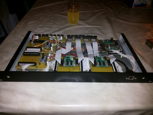
So an interface object (FGInterface Class) is created. From this object, methods will allow you to manage the interface. Devices will be created on the interface. Access to low level device is possible throught the interface device object, but this devices should not, except in some case, be called directely. Hardware communication is based on a Class python dedicated to the I2C protocol.
Then the cockpit elements are created on the interface and linked to one of the devices according to the configurations. At any time, an element can be get, checked or updated throught the interface object.
For memory :
- FG Int : An instance of the FGInterface Class. It's the "super" class. Instance of this class own all interface object.
- Device : Hardware chip. An instance of a device class give access to device management.
- Object : Cockpit hardware. A object class give all method to manage the object.
To link all classes, a protocol class have been implemented : I2CDevice. You should never call directly this class. All call needed should be done in the objects classes or in the devices classes.
In the I2CDevice class you will have access to very low level method, use to setup and configure different things on the I2C Buses and I2C Devives (set or read a buffer, or just a bit of one buffer ... etc)
Configuration
All the interface is ported by a set of configuration file. At startup, when you create the interface, configuration is read & store in the interface object.
3 configurations file minimum is needed :
- an interface configuration file.
Generics parameters can be found, as like interface name or module to be loaded. (Yeah interface is modular .. only needed things can be loaded)
- a devices configuration file.
Each devices are describe in this file. Devicename, deviceaddress and devicetype are the minimum to declare a device.
- devicename need to be unique.
- deviceaddr is unique on one I2C buses.
- devicetype is needed to create the device object to call the "good" library.
- an objects configuration file.
Each object (cockpit element) need to be defined. Properties depends from each elements type. A switch configuration will not be the same as a display configuration.
Example demo
Throughout the documentation the examples will relate to the airbus A330 design some panel regarding where actuor are
The radio panel will need 2 devices :
- 1 HT16K33 to manage displays & light function.
- 1 MCP23016 to manage switches & rotary encoders.
Function that will be created with the radio panel :
- Standby Frequency display (6 Digit, decimal point after the third digit)
- Active Frequency display (6 Digit, decimal point after the third digit)
- Push button to switch frequency
- Power Switch
- Double Rotary Encoder to manage Standby Frequency
Configuration files are describe on the FGInterface Class page


