Howto:Animate gear scissors using the tracking animation
A locked-track animation is an animation that can do exactly the same thing as the Locked Track constraint available in Blender. It is most commonly used to animate landing gear scissor (torque) links, but can also simulate any simple inverse kinematic system consisting of two rigid arms connected by a revolute joint (hinge).
How it works
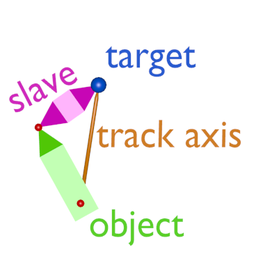
A scissors linkage has two arms connected by a middle hinge. One arm is attached to the gear leg (fixed end); the other is attached to the oleo strut and moves with it as it compresses and extends. The locked-track animation automatically rotates both arms so the middle hinge stays connected throughout that travel.
One <animation> block handles both arms. No parenting or grouping of objects in the 3D file is required, the animation works purely by object name.
There are only two axes required: the lock-axis and the track-axis. They must be orthogonal. The lock-axis is the axis of the hinge pin (the axis rotation occurs around). The track-axis is the direction the arm initially points in the rest-position geometry. Internally the track-axis is always orthonormalized to the lock-axis, as calculations are always performed in the plane normal to the lock-axis.
Parameter reference
| Parameter | Meaning |
|---|---|
object-name |
The upper scissor arm (attached to the gear leg) |
center |
The hinge point where the upper arm attaches to the gear leg i.e. the upper arm's pivot point |
target-name |
The object being tracked which is typically the oleo strut, since its position drives the animation |
target-center |
The point on the target object that the upper arm tracks toward i.e. where the lower arm attaches to the oleo strut |
lock-axis |
The direction the hinge pin points i.e. the axis the arms rotate around |
track-axis |
Direction vector from center to target-center in the rest position (see below)
|
slave-name |
The lower scissor arm |
slave-center |
The middle hinge point where the two arms meet |
Getting coordinates from Blender
All coordinates can be read directly from vertex positions. Select the vertex at the point of interest, read global coordinates from the N-panel, and use them directly in the XML.
center: select the vertex where the upper arm hinges on the gear legtarget-center: select the vertex where the lower arm attaches to the oleo strutslave-center: select the vertex where the two arms meet in the middletrack-axis: subtractcenterfromtarget-centeri.e.track-axis = target-center - center. Do not normalise itlock-axis: select the two vertices at either end of the hinge pin and subtract one from the other
Common mistakes
- Using a guessed
track-axissuch as(1, 0, 1)and this must be the actual rest-position direction vector, not an approximation - Setting
slave-namethe same astarget-namethese must be different objects - Forgetting that
track-axisdepends on the rest geometry if you reposition objects in the 3D file you must recompute it - Note that the sign of
track-axisdoes not matter, but the sign oflock-axisdoes.
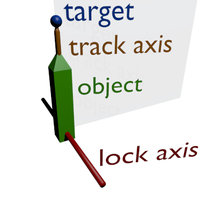
Initial pose
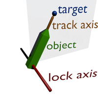
The target has moved and the
locked-trackanimation ensures the object still points at the target (with thetrack-axis)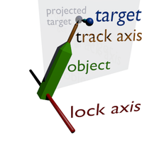
The target is projected into the plane defined by the object center and the
lock-axisbefore thelocked-trackanimation is applied.
Slave center/object
The slave-center specifies the location of the middle revolute joint. The slave-name object (the lower arm) is automatically rotated around slave-center to follow the upper arm, so both arms always exactly fill the space between their two anchor points.
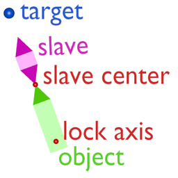
Initial pose
The target has moved and the
locked-trackanimation ensures thetrack-axisstill points at the target. Theobjectand theslave-objectare rotated such that the available space is exactly filled (aka scissor animation).
Examples
Basic locked-track (no slave)
Basic usage which is same behaviour as the Locked Track constraint in Blender. One object tracks a target point, rotating around the lock-axis:
<?xml version="1.0" encoding="utf8"?>
<PropertyList>
  <animation>
    <type>locked-track</type>

    <object-name>ADS Arm - Fuselage.r</object-name>
    <center>
      <x-m>4.9</x-m>
      <y-m>1.47</y-m>
      <z-m>3.82</z-m>
    </center>
    <lock-axis>
      <x>0</x>
      <y>1</y>
      <z>0</z>
    </lock-axis>
    <track-axis>
      <x>0.75</x>
      <y>0</y>
      <z>-0.662</z>
    </track-axis>

    <target-name>ADS Arm - Ramp.r</target-name>
    <target-center>
      <x-m>7.969</x-m>
      <y-m>1.475</y-m>
      <z-m>1.11</z-m>
    </target-center>

  </animation>
</PropertyList>
Gear scissor in a single animation block
The standard scissors animation. One <animation> block drives both arms. object-name is the upper arm; slave-name is the lower arm. No parenting of objects in the 3D file is required.
<?xml version="1.0" encoding="utf8"?>
<PropertyList>
  <animation>
    <type>locked-track</type>

    <object-name>ScissorsUpper</object-name>
    <center>
      <x-m>-4.00</x-m>   <!-- upper arm pivot on gear leg -->
      <y-m>0.10</y-m>
      <z-m>-1.20</z-m>
    </center>
    <lock-axis>
      <x>0</x>
      <y>1</y>           <!-- hinge pin runs left/right -->
      <z>0</z>
    </lock-axis>
    <track-axis>
      <x>0.19</x>        <!-- target-center minus center -->
      <y>0</y>
      <z>-0.23</z>
    </track-axis>

    <target-name>OleoStrut</target-name>
    <target-center>
      <x-m>-3.81</x-m>   <!-- lower arm pivot on oleo -->
      <y-m>0.10</y-m>
      <z-m>-1.43</z-m>
    </target-center>

    <slave-name>ScissorsLower</slave-name>
    <slave-center>
      <x-m>-3.90</x-m>   <!-- middle hinge where arms meet -->
      <y-m>0.10</y-m>
      <z-m>-1.31</z-m>
    </slave-center>
  </animation>
</PropertyList>
Disabling tracking with a condition
Use a condition to disable tracking and optionally apply a fixed rotation while disabled:
<?xml version="1.0" encoding="utf8"?>
<PropertyList>
  <animation>
    <type>locked-track</type>

    <condition>
      <property>/controls/gear/nose-wheel-steering</property>
    </condition>
    <disabled-rotation-deg>-90</disabled-rotation-deg>

    <object-name>Torque Link Upper Arm</object-name>
    <center>
      <x-m>-9.785</x-m>
      <y-m>0</y-m>
      <z-m>1.04</z-m>
    </center>
    <lock-axis>
      <x>0</x>
      <y>1</y>
      <z>0</z>
    </lock-axis>
    <track-axis>
      <x>0.022</x>
      <y>0</y>
      <z>-1</z>
    </track-axis>

    <target-name>Torque Link Lower Arm</target-name>
    <target-center>
      <x-m>-9.789</x-m>
      <y-m>0</y-m>
      <z-m>0.454</z-m>
    </target-center>

    <slave-center>
      <x-m>-10.033</x-m>
      <y-m>0</y-m>
      <z-m>1.035</z-m>
    </slave-center>
  </animation>
</PropertyList>
Lessons learned
Scissors - with parenting

As seen to right, we have an oleo strut and a gear leg. The oleo strut has a compression animation which uses a translate animation to move up or down according to gear compression. There are two torque links, the top is called NLGTorqueLink1 and the bottom NLGTorqueLink2.
Note: parenting the bottom link to the top link in the 3D file is not required for the animation to work as the animation engine references objects by name only. The "with parenting" approach shown here is one valid modelling choice but is not mandatory, and may be problematic depending on the 3D file format being used (e.g. AC3D does not support poly objects with sub-objects).
After the translation animation, set up a locked-track animation on NLGTorqueLink1. The center is the hinge of the top scissor arm; target-name is the oleo strut which translates; slave-name is the bottom scissor arm; and slave-center is where the two arms meet.
	<animation>
		<type>locked-track</type>
		<object-name>NLGTorqueLink1</object-name> <!-- upper -->
		<center>
		  <x-m>-13.468</x-m>
		  <y-m>-0.006419</y-m>
		  <z-m>-3.34389</z-m>
		</center>
		<lock-axis>
		  <x>0</x>
		  <y>-1</y> <!-- inverting lock-axis gives incorrect results -->
		  <z>0</z>
		</lock-axis>
		<track-axis> <!-- sign of track-axis does not matter -->
		  <x>0.100957</x>
		  <y>0.569667</y>
		  <z>0.001675</z>
		</track-axis>

		<target-name>NLGSlidingTubeAxle</target-name> <!-- oleo strut -->
		<target-center>  <!-- where lower arm attaches to oleo -->
		  <x-m>-13.569</x-m>
		  <y-m>-0.004744</y-m>
		  <z-m>-3.91356</z-m>
		</target-center>

		<slave-name>NLGTorqueLink2</slave-name>
		<slave-center>  <!-- middle hinge -->
		  <x-m>-13.2685</x-m>
		  <y-m>-0.005584</y-m>
		  <z-m>-3.67419</z-m>
		</slave-center>
	</animation>
Scissors - without parenting
In most cases you should use the single animation block method above. The two-block approach shown here is an alternative where each arm tracks the other rather than both tracking an external object such as an oleo strut. This may be useful in the rare situation where there is no suitable external moving object to use as the target -- for example, a scissors linkage that connects two points that both move independently, with neither one being the natural "driver". If you have an oleo strut or other clearly moving reference object, use the single-block method instead.
The way this works: each torque link rotates around its base (where it meets the oleo strut or gear leg), locked on the Y-axis. Each arm's target-name is the other arm, target-center is the middle hinge point, and slave-center is the other arm's base pivot.
	<animation>
		<type>locked-track</type>
		<object-name>NLGTorqueLink2</object-name> <!-- lower -->
		<center>
		  <x-m>-13.569</x-m>
		  <y-m>-0.004744</y-m>
		  <z-m>-3.91356</z-m>
		</center>
		<lock-axis>
		  <x>0</x>
		  <y>1</y>
		  <z>0</z>
		</lock-axis>
		<track-axis>
		  <x>0.100955</x>
		  <y>0.569668</y>
		  <z>0.001675</z>
		</track-axis>

		<target-name>NLGTorqueLink1</target-name>
		<target-center>  <!-- middle hinge -->
		  <x-m>-13.2685</x-m>
		  <y-m>-0.005584</y-m>
		  <z-m>-3.67419</z-m>
		</target-center>

		<slave-center> <!-- upper arm base pivot -->
		  <x-m>-13.468</x-m>
		  <y-m>-0.006419</y-m>
		  <z-m>-3.34389</z-m>
		</slave-center>
	</animation>

	<animation>
		<type>locked-track</type>
		<object-name>NLGTorqueLink1</object-name> <!-- upper -->
		<center>
		  <x-m>-13.468</x-m>
		  <y-m>-0.006419</y-m>
		  <z-m>-3.34389</z-m>
		</center>
		<lock-axis>
		  <x>0</x>
		  <y>1</y>
		  <z>0</z>
		</lock-axis>
		<track-axis>
		  <x>-0.100955</x>
		  <y>-0.569668</y>
		  <z>-0.001675</z>
		</track-axis>

		<target-name>NLGTorqueLink2</target-name>
		<target-center>  <!-- middle hinge -->
		  <x-m>-13.2685</x-m>
		  <y-m>-0.005584</y-m>
		  <z-m>-3.67419</z-m>
		</target-center>

		<slave-center> <!-- lower arm base pivot -->
		  <x-m>-13.569</x-m>
		  <y-m>-0.004744</y-m>
		  <z-m>-3.91356</z-m>
		</slave-center>
	</animation>
3 axis locked-track animation
Sometimes an object requires rotation in more than one plane which is often a hydraulic actuator with a ball joint. Since a single locked-track animation always needs at least one locked axis, this is handled by chaining two animations on the same object: one locking Y, immediately followed by one locking X, with all other parameters identical.
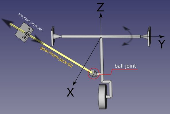
3 axis locked-track animation example.

First, lock the Y axis and point the object at the target:
    <animation>
        <type>locked-track</type>
        <object-name>gear-front-jack-02</object-name>
        <center>
            <x-m>-2.91953</x-m>
            <y-m>-0.06230</y-m>
            <z-m>-1.30829</z-m>
        </center>
        <lock-axis>
            <x>0</x>
            <y>1</y>
            <z>0</z>
        </lock-axis>
        <track-axis>
            <x>1</x>
            <y>-0.23</y>
            <z>0.630</z>
        </track-axis>
        <target-name>BOX_GEAR_GREEN.000</target-name>
        <target-center>
            <x-m>-2.04543</x-m>
            <y-m>-0.23232</y-m>
            <z-m>-0.82533</z-m>
        </target-center>
    </animation>
Immediately below it, add an identical block locking the X axis instead:
    <animation>
        <type>locked-track</type>
        <object-name>gear-front-jack-02</object-name>
        <center>
            <x-m>-2.91953</x-m>
            <y-m>-0.06230</y-m>
            <z-m>-1.30829</z-m>
        </center>
        <lock-axis>
            <x>1</x>
            <y>0</y>
            <z>0</z>
        </lock-axis>
        <track-axis>
            <x>1</x>
            <y>-0.23</y>
            <z>0.630</z>
        </track-axis>
        <target-name>BOX_GEAR_GREEN.000</target-name>
        <target-center>
            <x-m>-2.04543</x-m>
            <y-m>-0.23232</y-m>
            <z-m>-0.82533</z-m>
        </target-center>
    </animation>
The track-axis
The track-axis is the direction the arm points in the rest position, i.e. the position the object occupies in the 3D file before any animation is applied. The correct value is simply:
track-axis = target-center - center
Read both points directly from vertex coordinates in your 3D application and subtract. Do not normalise the result. Do not guess a round value like (1, 0, 0) and even a small error here will cause the arm to start at the wrong angle.
Note that the coordinates use the plain <x>, <y>, <z> form (unitless direction vector), not the <x-m> form used for world-space positions.
Tips
AC3D users
The animation works by object name only and does not require any parent-child relationship between objects in the 3D file. If you are working with .ac files, do not attempt to nest a POLY inside another POLY to create parenting this violates the AC3D format and the editor will behave unpredictably. Simply name the objects correctly in the XML and the animation will work without any grouping in the file.
Using Blender
If you build your model in Blender you can verify the scissors animation before export by adding an armature with two bones, applying an IK constraint to the second bone tracking the target object, and attaching each scissor arm to its bone. The animation you see in Blender with this setup is exactly what the locked-track XML will produce in FlightGear.