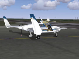
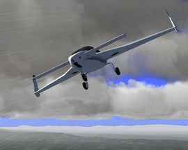
Velocity XL RG
| Buckaroo's Hangar | ||
|---|---|---|
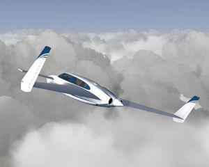 Velocity XL RG in flight | ||
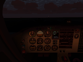
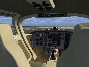 Velocity XL RG cabin | ||
| Type | Civil aircraft, Civil utility aircraft | |
| Configuration | Canard aircraft, Pusher aircraft | |
| Propulsion | Propeller aircraft, Single-engine aircraft | |
| Manufacturer | Velocity | |
| Author(s) | Gary Neely | |
| FDM | YASim | |
| --aircraft= | Velocity-XL-RG | |
| Status | Unknown | |
| Development | ||
| Website |
| |
| Download |
| |
| License |
| |
| ||
|
| ||
The Velocity XL is an American amateur-built aircraft produced by Velocity, Inc. Introduced in 1997, the Velocity XL (Extra Large) is an enlarged version of the Velocity SE, featuring a roomier cabin and accommodations for a larger engine. The Velocity XL is available to builders in kit form and features several kit variations, including options for retractable gear (the RG designator) and a belly-mounted airbrake. Using an IO 540 engine, the aircraft is capable of cruising up to 200 kt, and can achieve a range of over 1300 nm at 65% power.
Aircraft Features
Model
- The model was built using the factory builder's guide and several builder's blogs as references. All flight surfaces and moveable objects animate as expected, including the gull-wing doors. Engine/prop sound is based on a real Velocity IO-540. The model was made with optimization in mind and should perform well on relatively modest computers. It was not intended for "Rembrandt".
- A simplified "AI" version is available for those wishing to see the model in multi-player, but not fly it. Visit the model's home page found in the External Links section below to get the "AI" version.
Cabin Modeling
- Fully detailed cabin featuring complete instrumentation and avionics with a fully implemented electrical system. The cabin is configured with variable lighting for night flights based on a real Velocity lighting installation.
Livery System
- The model features several livery schemes with both a 1024x1024 and a 2048x2048 version. The default livery is a light-weight 1024x1024 scheme that should play nicely in a multi-player environment.
Engine Simulation
- A unique engine simulation allows the pilot to monitor temperatures and fuel flow and meaningfully set mixture and propeller settings for economy or power.
Aircraft Controls
Keyboard Shortcuts
| Key | Function |
|---|---|
| Ctrl+b | Toggles both rudders to maximum deflection as airbrake |
- All other functions use Flightgear standard key mappings.
Clickable Levers and Sliders
Most levers and sliders in the cockpit are clickable. You can use LMB to increase value/position and MMB to decrease the value/position, or you can use the scroll wheel to make finer adjustments.
Limitations
| V speed | Speed in kts |
|---|---|
| VS | 65 |
| VR | 75 |
| VLE | 110 |
| VLO | 120 |
| VNO | 140 |
| VNE | 200 kias |
Quick Startup
- Set fuel to 'Both'
- Turn on the master battery
- Turn on the fuel boost pump
- Turn on the left and right magneto switches
- After fuel pressure comes up, use the starter switch to start the engine
- Turn off fuel boost pump (optional)
- Turn on alternator switch
- Turn on avionics switch
- Set your altimeter to the proper pressure
- Check your heading gyros and set as necessary
- Set elevator trim as desired (the Velocity menu features a suggested setting)
- Release parking break when ready
- An automagic startup function can be found in the "Velocity" section of the menu bar.
Steering and Brakes
The Velocity nose wheel casters and is not steerable. Steering is accomplished by differential braking. This makes the Velocity handle very tightly on the ground, but requires attention on takeoff until the rudders are effective.
The standard Velocity kit couples braking with rudder deflection, but like many builders, this model uses a toe-brake option to de-couple rudder and braking.
Weight and Balance
The plane's default load is rather light, having a single pilot, some nose ballast and a modest fuel load. This makes the default experience exceptionally nimble and responsive. Use the Equipment menu to experience the more typical real-world load options.
The real Velocity is fairly sensitive to weight and balance. It's critically important not to have the CG too far back, which can result in flat stalls or other not so good behaviors. Changes to the Velocity's wings have largely eliminated the flat stalls, but careful attention to weight and balance is still essential for safe flying. The model's CG and weight have been configured using real-world Velocity weight and balance worksheets. See the file "velocity-xl-rg-yasim.xml" for more notes and information.
Fuel
A Velocity XL with retractable gear has two 33 gallon tanks located in the leading half of the inboard wing segments known as the "strakes". Each tank is essentially a hollowed-out portion of the strake, provided with baffles and coated with fuel-proof epoxy. A corresponding sight gauge to either side of the rear seats indicates the load of each tank. A 4 gallon sump tank sits low against the firewall behind the rear seats, though only 2.5 gallons are usable. Note that the main panel fuel instrument shows the capacity of the two main tanks-- there is no readout for the sump. If your two main tanks are showing empty, you'd better have an airfield in sight.
The base Velocity build has a very simple fuel feed. Both tanks feed the sump which feeds the engine with no valves or selectors. Like some Velocity builders do, this model adds a fuel control switch to allow left-right-both-off settings.
You need the boost pump only for cold engine starting. After fuel pressure has come up and the engine is started, you should turn it off, otherwise it will cost you additional fuel. You might wish to leave it on during the early stages of your climb and turn it on for approach. The boost pump can be used to further richen the mixture if cylinder temps get too hot, but at the expense of extra fuel. Mixture is auto-enriched at high power settings, so you don't really need this on for take-off.
Airbrakes
The Velocity's twin vertical stabs have independent one-way rudders; travel is outboard for each. Because of this both rudders can be deployed simultaneously, deflecting each rudder outboard as a form of speed braking. The effect is relatively weak but helpful. Expect a slight pitch-up effect when using the rudders in this way.
Since rudders can be deployed independently, the rudder pedals are not coupled in the standard Velocity build. This may not work with many rudder pedal sets, where the pedals pivot about a center point. In this case, you can use the ctrl-b function to toggle both rudders to maximum deflection. Note that rudder control is effectively disabled while set this way. An indicator light on the main panel displays this condition. This light isn't a real Velocity indicator, only a sim aid.
Some Velocity builds incorporate a bellyflap speedbrake for more effective airbraking. The model does not have this feature and won't until details become available on how the aircraft reacts to its deployment.
Flying
Normal flight is responsive and free of any quirks. The author is not a pilot, has never been in a Velocity, and makes no claim that the model flies true to the real thing. That said, the model conforms fairly closely to the pilot's handbook. If you stay within normal flight profiles it should not do anything peculiar.
Takeoff
Lift the nose at 60-70 kts, then rotate at 75, 80-85 if operating at heavy gross weights. Trimming for takeoff helps. Try not to touch the brakes too much to steer on the takeoff roll. The rudders will become effective above 25 kts. Don't rotate too far especially with a light load (aft CG), as you could place the CG aft of the main gear and tip the Velocity on its tail. (In the real Velocity you risk prop damage.) Never rotate the canard above the horizon.
The Velocity is a pusher-configuration, so expect propeller effects to be reversed from what you might be accustomed to.
Climb
Optimum climb is 100 knots. Best climb is 80, and for optimum visibility and cooling, 110. Climb with WOT (wide open throttle), reducing RPM as desired and leaning as desired.
Cruise
Consider running your Velocity at WOT and adjusting power using mixture and propeller controls. Remember to turn the fuel pump off. You should get your best economy this way. See the engine section for tips on power settings.
The model features the Lycoming IO-540-K 300 HP engine. With the default light load, this gives you a lot of power to play with, and is necessary to achieve the top end speeds. Note that while the design is capable of very high speeds in mild air, many Velocities don't achieve those speeds. Top speed depends on flight conditions, engine, the quality of the build, the propeller and pitch settings, and other factors.
Descent
Plan your descent well in advance of your destination. The Velocity is very slick and will take a while to shed speed. Although the simulation won't care, it's recommended that you reduce power gradually in increments of 1" every minute or so in order to minimize possible negative effects on your engine.
Approach
Enter the pattern at 85-90 kts, approach at 80. Flare slightly and land at 70-75. Add 5 knots for heavy loads. This is a very clean airplane-- don't approach too fast or you could easily double your runway needs. Again, plan your approach well in advance or you may need to go-around due to excessive speed. (This advice is straight out of the pilot's handbook for those who may be thinking this is an FDM flaw-- it's not. The Velocity is very slippery.) Use the rudder-brake to help control your descent, but remember to unlock it before crossing the threshold. Fly the aircraft down to the runway-- don't try to stall the aircraft to a landing or use excessive flare.
Stalls
Stall is listed at 65 kts, but varies considerably with the build and the load. The handbook reports the aircraft is manageable and responsive down to 60 kts with lighter loads.
Due to the canard configuration, a "stall" in the Velocity is more like a nose bobbing motion, where you can no longer keep the nose up. With the stick fully back in low-speed flight, you will reach a point where the elevator begins to stall before the wing, dropping the nose and picking up lift again such that the nose begins to come up. You may notice a slight oscillation in pitch when this begins to happen, called "pitch bucking". This video demonstrates the effect: http://www.youtube.com/watch?v=zeTjPPpVtuU Watch carefully for the pitching oscillations. For another demonstration: http://www.youtube.com/watch?v=M-dGCUsZvDY, at about 5:11 into the video.
Because the aircraft has small tires and an aft-mounted propeller, the Velocity is not recommended for rough or grass fields. The Velocity is also not recommended for short fields due to its relatively long runway needs.
Avionics
Comm, Nav and ADF function as you would expect. Nav 1 (the top radio) is linked the the RMI in the bottom left corner. Nav 2 (the 2nd radio down) is linked to the CDI, bottom center. The ADF receiver (3rd panel down) operates on the RMI and the ADF. The ADF is superfluous, but is present for practice with such older instruments.
The audio board currently doesn't do much except provide marker beacon lights and the ability to disable the marker beacon receiver.
The transponder has no functionality, but it's there if you want to emulate procedures. It does have all the animations and control mappings necessary for operation, and could easily be adapted to work with any Flightgear transponder implementation.
For more on the avionics, see the file "README_avionics.txt".
Engine Modeling
This Velocity model features a new and experimental engine simulation created by the author. The system replaces most YASim values with custom calculations. The system is based on maintaining reasonably correct air-fuel ratios combined with tabular data for engine temperatures and other information. The result allows you to find best power or best economy settings while keeping your cylinder temps reasonable.
The EDM (Engine Data Management) instrument is very loosely like a JP Instruments EDM. Its main function is to report engine cylinder EGT and CHT values. (The device does not yet model other EDM capabilities.) The EGT and CHT numbers report a kind of average value, though the individual bars do report true to their cylinders. I've taken some liberties with the size and positioning of the readouts for legibility.
Note that oil temperature reads in degrees Centigrade, while other temps are degrees Fahrenheit.
Play with the the power and mixture controls while watching EGT, the HP estimate, and fuel flow to find your best power or economy settings at your altitude. Best economy is approximately 50 degrees lean of peak EGT, while best power is about 80 degrees rich of peak EGT. The CHT values will tell you when you're getting into troubling regions. The default cylinder temperature ranges are set very conservatively so you shouldn't have any problems; just keep CHT's out of the red. Remember that EGT responds nearly instantaneously, while cylinder temps take a while to build up or cool down. The engine has an auto-rich feature, so as you push the throttle in beyond 65% you will also begin richening the mixture.
A real pilot will likely find the numbers a bit off-- the model's numbers are based on some real data, some data for similar engines, and some guesses. The author has no experience with these engines and what their temps do at various power settings. If you have experience with the Lycoming IO-540-K or similar and have better numbers, feel free to adjust the temperature tables found in "Systems/Velocity-XL-RG-engine.XML"; if you send me your recommended changes, I'll use them. See that file and the related nasal script for more information.
For notes on the development of this engine simulation, see:
Ground Shadow
The model features a simple object-based shadow to provide a reference when taking off and landing in chase view. It's enabled at elevations of less than 100m, when gear is down, and the sun is reasonably up. It works tolerably well for its purpose, especially when the sun is well up since it doesn't move with the sun (not worth the effort right now). If you don't like or need this fake shadow, simply disable it using the Velocity menu option. Your preference will be saved if you use the Flightgear exit option.
Other Stuff
The three NACA scoops on the upper aft cabin are two engine cooling intake ducts, and a smaller cabin air intake. The engine cooling outlets are located to either side of the propeller. On the left side of the nose is another NACA scoop, this one is the intake for the secondary engine oil cooler (which also provides cabin heat). Below this and aft of the nose gear doors is the exhaust for the oil cooler. Some Velocity builds have an intake on the right side of the nose for a cabin air intake, and some have additional intakes in the engine cowl, probably for oil coolers and/or revised air intakes.
Those familiar with the aircraft may notice the lack of cowl retaining screws. I learned some builders create a retaining flange on the forward cowl that slips under the fuselage skin just aft of the firewall. That holds down the forward section. On the aft cowl, standard hardware hinges are fixed inside the cowl, half the hinge on the upper cowl, the other half on the lower cowl. They mate together perfectly, and the removable hinge pins holds the two hinge halves and therefore the cowl halves together. It's simple, hidden from view, has no screws to come loose and hit the prop, and looks clean. I thought it amazingly clever, and decided to assume my model uses that technique. And it saves me from exactly placing those damned screws.
A few external details are missing: the "sparrow strainer" which assists trimming the elevator at higher speeds and elevator counterweights, which the author simply forgot to model (sorry). The latter are hard to see anyway, so it's not a big deal. Inside, the rudder cables that run to the pedals are missing, but unless you know what to look for, you'd never notice this.
For more notes about the model, see the YASim configuration file and the nasal script files.
External Links
For more information, updates, paint kits, etc., visit:
