Howto:Build your own Panel or Cockpit - Prototype for Switch Banks using Microchip MCP23S17
Prototype for Switch Banks using Microchip MCP23S17
Switch Bank Prototyping Goals
- Show that the Microchip MCP23S17 and 16 resistors can be used the construct 16 banks of 16 switches each with software to sense the position of each switch.
- Test the switch bank
Switch Bank Software
- Node.js with Raspberry Pi
- MCP23S17Test.js
- The test routine sets up the two MCP23S17 chips.
- Chip Address 000 will be used for the 16 inputs, which will contain the data from each switch in a single bank at any given time.
- Chip Address 001 will initially have each of its pins set as inputs, with a pull up resistance set.
- One at a time, the gpio pins on Chip Address will be set as an output with the value of 1. All the remaining pins will remain as inputs with the pull up set. The inputs are not going to matter, we're only interested in the current from that one output pin flowing to the selected bank.
- Chip Address 000 will be read, giving the values of the switch settings in the 16 switches in the bank corresponding to the current output line on Chip Address 001
- Debouncing in software will be done by noting the previous state of the switch, and ignoring any change back to that state for a short period of time.
- The test routine sets up the two MCP23S17 chips.
Switch Bank Parts List
| 2 | Microchip MCP23S17 |
| 16 | 320 Ohm Resistors |
| 1 | Raspberry Pi |
| 1 | Raspberry Pi Breadboard Connector |
| 5 | Breadboard & Jumper Wires of various sizes. if you have the flat ribbon cable with pins on each end, you can break off 4 sets of 8. |
| several | Rotary switches, spdt switches |
Switch Bank Pictures

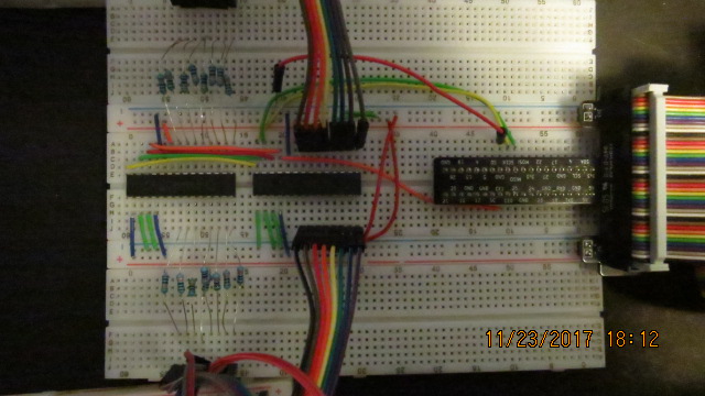
Up to eight MCP23S17 chips can be present on a single SPI Bus. Each chip is given an address in the range 0-7 and individually addressed in the chip's SPI communication protocol.
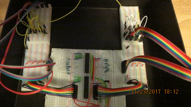
2 Breadboards wired to simulate switches connected to 2 MCP23S17 chips. The circuit supports up to 256 individual switches.
[| Microchip MCP23017/MCP23S17 Datasheet
Switch Bank Construction
There are two types of breadboard. You want the ones with power strips that are broken in the middle. The red and blue stripes indicating + and - are broken in the middle to indicate that there are actually 4 separate + & - busses on each breadboard.
- Cut off the power strips from four breadboards using a sharp knife.
- Snap the 8 double power strips together to form a single breadboard with 32 25 pin busses. The ones at the top label as "Output Common Points". Label the ones on the bottom "Input Common Points". In the picture above, the 8 double strips are split into two groups of 4.
- Install the raspberry pi 40 pin adapter at the top of a breadboard with the usual two power strips.
- At the bottom of the breadboard place the two MCP23S17 chips with pin 1 toward the top.
At the top of the upper left power strip, the adapter provides 3.3 volts. At the top of the right power strip it's 5v. We're going to use only 3.3 volts.
- At the bottom of the upper left 3.3v bus, wire 3.3v to both bottom power strips so 3.3v is on both sides of the MCP23S17 chips. Be sure you are not wiring the 3.3v output of the pi to it's 5 volt supply. That would be bad. Check your work.
Supply the chips with power: On each MCP23S17
- Wire 3.3v power (+) to the Vdd and ~Reset
- Wire ground(-) to Vss
- set the address to 000 or 001. 000 is 3 pins wired to ground (-). 001 is two wired to ground and one to Vdd (+). make sure you have the order right and you haven't set up address 100 instead of 001.
- connect the four corresponding SPI pins on the MCP23S17s together.
On one MCP23S17,
- connect the four SPI pins from the Raspberry Pi to the corresponding SPI pins on the MCP23S17s
- Wire the 16 IO Pins of the MCP23S17 with address 001 to 16 330 ohm resistors.
- Wire the other side of the resistors to the 16 "Output Common Points"
- Wire the "Input Common Points" to the inputs of the MCP23S17 with address 000
You now have a set of 16 bank outputs and 16 bank inputs. The inputs and outputs are labeled 0-9 and A-F Each of the 256 combinations of one of the outputs and one of the inputs is now an "open" "switch". Connect output 0 and input A with a jumper and you have closed one switch. Switch# 10 counting from zero. Connect output 3 and input 7 and you've closed switch # 39
If you run the test program, you will see "0000".
Get ready to throw a lot of switches.
- Wire each of the "Output Common Points" to each other.
- Wire each of the "Input Common Points to each other.
If you run the test program, you will still see "0000".
- Place a single wire between "Output Common Point" 0 and "Input Common Point" 0
You now have a full set of 256 "closed" switches.
If you are running the test program, you will see "FFFF"
- Undo the wire between output bank E and F. 16 switches are now off. The rest remain on.
- Undo the wire between inputs E and F. 15 more switches are now off. The rest remain on.
- Plan the switch wiring for your cockpit.
- Estimate the cable runs for groups of 4 or 8 switches in your cockpit.
We're going to try two types of wiring for switches:
- 1 pair in the Cat 5 per switch
- 1 of the 8 wires in the cat 5 per switch with an extra wire wrapped around the outside of the cat 5 cable
You can strip the outer covering from the cable or not as you prefer.
- If you have a plan for the wiring of your cockpit, you can cut pieces of Cat5 and other wire for this prototype that can later be used in the actual cockpit. Leave about 1'-2' extra on each piece you cut. In any case, cut pieces of Cat 5 cable to the lengths you've estimated for various parts of the cockpit.
In my case, I wanted to a more complete test of the full capabilities of the circuit. I actually need less than 100 switches. I plan to do individual pair wiring for 128 switches and individual wire with a return wire for 128 more. so 128/4 + 128/8 + 8 wires = 48 pcs cat 5. 200 feet of cable can be had for about $10 USD. That will yield 40 5' pieces. I can cut a few down to 2' and 3' to end up with the 48 sets I want for the test and can use some of the pieces later for wiring in the cockpit. I'm planning the test in stages, so I'm not cutting the wire just yet. I want to find out what happens when a switch is at the end of a 200' of cat5 wire.
- Make up a test switch board with as many switches as you have available and want to bother wiring up ahead of time. Use a combination of spst, spdt and rotary switches. You don't need too many, the rest can be done using the breadboards at the ends of the wires.
- Do testing through the cabling to ensure that the extra capacitance, inductance, and potential emi interference doesn't break the switch bank.
Switch Bank Tests & Results
| Show that switches in more than one bank are correctly supported | |||||||
| Show that switch bouncing is eliminated using software and hardware | |||||||
Show correct behavior and reasonable total current draw when
| |||||||
Show correct behavior when
|
MCP23S17test.js
let rpio = require('rpio')

class SwitchbankSPI {
  constructor() {
    this.IODIRA = 0
    this.IOCONA = 0x0A // For setting HAEN
    this.GPIOA = 0x12 // For Reading and Writing
    this.GPPUA = 0x0C
    /*
     * mcp23s17 # 0 does inputs
     * mcp23s17 # 1 will do 1 output at a time, but the other 15 are set as
     *            inputs so their connection to the switches has no effect
     *            and we can cleanly read the 16 switches based on the only
     *            output being set to low.  Any closed switches in the
     *            corresponding bank will result in a low at the input for that
     *            switch.  any closed switches in the other banks will remain
     *            high because the "output" channel is set to input and pulled
     *            high
     *
     */
    this.txbufIODIRA0 =
      new Buffer([0x40, this.IODIRA, 0xff, 0xff])
    this.txbufIODIRA1set =
      new Buffer([0x42, this.IODIRA, 0xff, 0xff])
    this.txbufGPIOread =
      new Buffer([0x41, this.GPIOA, 0x00, 0x00])
    this.rxbuf= new Buffer([0x00, 0x00, 0x00, 0x00])

    rpio.spiBegin();
    rpio.spiChipSelect(0);			       /* Use CE0 */
    rpio.spiSetCSPolarity(0, rpio.LOW);	/* MCP23S17 is Active Low */
    rpio.spiSetClockDivider(256);	  /* MCP23S17 max is 10MHz, 128 == 1.95MHz */
    rpio.spiSetDataMode(0);
    rpio.init({gpiomem: false, mapping: 'gpio'});

    let txbuf = new Buffer([0x40, this.IOCONA, 0x08]); // set HAEN
    let rxbuf = new Buffer(txbuf.length);
    rpio.spiTransfer(txbuf, rxbuf, 3)

    txbuf = new Buffer([0x40, this.GPPUA, 0xff, 0xff]); // set GPPU
    rpio.spiTransfer(txbuf, rxbuf, 4)
    txbuf = new Buffer([0x42, this.GPPUA, 0xff, 0xff]); // set GPPU
    rpio.spiTransfer(txbuf, rxbuf, 4)
    txbuf = new Buffer([0x43, this.GPPUA, 0xff, 0xff]); // set GPPU
    rpio.spiTransfer(txbuf, rxbuf, 4)
  }
  readSwitchBank(bank) {
    let m=(bank) %8
    let c = 0x01<<m
    let d = ~c & 0xff
    let b = bank>7? d : 0xff
    let a = bank<=7?d: 0xff
    this.txbufIODIRA1set[2] = 0xff
    this.txbufIODIRA1set[3] = 0xff
    rpio.spiTransfer(this.txbufIODIRA1set, this.rxbuf, 4)
    this.txbufIODIRA1set[2] = a
    this.txbufIODIRA1set[3] = b
    rpio.spiTransfer(this.txbufIODIRA1set, this.rxbuf, 4)

    rpio.spiTransfer(this.txbufGPIOread, this.rxbuf, 4)

    return ~((this.rxbuf[3]<<8) + this.rxbuf[2]) & 0xffff
  }
}
class SwitchBank {
  constructor(n) {
    this.switches = []
    this.bounce1 = 0
    this.bounce2 = 0
    this.bounce3 = 0
    this.switchbankSpi = new SwitchbankSPI()
    switch (n%16 >0) {
      case 0: this.banks = n/16
      break
      default: this.banks =(n + 16 - (n % 16)) /16
    }

    for (let i=1; i<=this.banks; i++) {
       this.switches = this.switches.concat([0x0000])
    }
  }
  getSwitches() {
    return this.switches
  }
  scan() {
    for (let bank= 0; bank < this.banks; bank++) {
      let bankResult = this.switchbankSpi.readSwitchBank(bank)
      if (bankResult != this.switches[bank]) {
        console.log('Changed bank ' + bank
        + 'from: ' + this.switches[bank].toString(16)
        + ' to: ' + bankResult.toString(16))
        let d0 = new Date()
        setTimeout( this.update.bind(this), 10,
        bank, this.switches[bank], bankResult, d0.getTime())
        this.switches[bank] = bankResult
      }
    }
  }
  update(bank, original, latest, detectedAt) {
    console.log('updating')
  }
}

sb = new SwitchBank(255)
  while(1){
sb.scan()};
