Edgley Optica
| Buckaroo's Hangar | ||
|---|---|---|
 Edgley Optica | ||
 Optica cabin | ||
| Type | Civil aircraft, Civil utility aircraft, Special-purpose aircraft | |
| Configuration | High wing aircraft | |
| Propulsion | Piston aircraft, Single-engine aircraft, Ducted fan-powered aircraft | |
| Manufacturer | Edgley | |
| Author(s) | Gary Neely | |
| FDM | YASim | |
| --aircraft= | Optica | |
| Status | Unknown | |
| Development | ||
| Website |
| |
| Download |
| |
| License |
| |
| ||
|
| ||
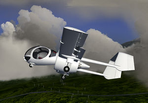
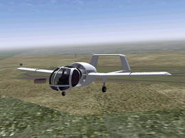
The Optica is a light civilian observation aircraft meant to be a relatively low-cost alternative to helicopters. 25 examples of this unique and innovative aircraft were built in the late 70's through mid 80's: 2 prototypes + 23 production aircraft. This model is a hybrid of Opticas rather than a particular series because information about this rare aircraft is equally rare. To build up a reasonable picture of the Optica, I've had to use as many sources as possible. I label it as an OA7 due to the type certificate I used for some of the raw data.
Aircraft Features
Model
- The model was built using a variety of references, though factory drawings were not available. I have cross-checked model details as much as possible given the limited materials and believe the model to have rather good fidelity. All flight surfaces and moveable objects animate as expected. The engine sound is based on a real Velocity IO-540. The model was not intended for "Rembrandt".
Cabin Modeling
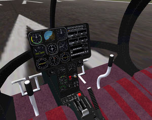
- Fully detailed cabin featuring complete instrumentation and avionics with a fully implemented electrical system. The cabin is configured with variable lighting for night flights. There are a few other Optica simulations out there, but this one has by far the most accurate interior.
Livery System
- The model features several livery schemes at 1024x1024 resolution.
Engine Simulation
- The Optica features meaningful numbers for all engine-related instruments.
Aircraft Controls
Keyboard Shortcuts
The Optica uses standard Flightgear key mappings.
Clickable Levers and Sliders
Most levers and sliders in the cockpit are clickable. You can use LMB to increase value/position and MMB to decrease the value/position.
Limitations
| Speed in kts | |
|---|---|
| Vs | 42 |
| Vs0 | 38 |
| Vr | 50 |
| V2 | 55 |
| VA | 113 |
| Vno | 115 |
| Vne | 140 kias |
| Vfe | 1-10 deg, 110 kts 11-50 deg, 85 kts |
Quick Startup
- Turn on the battery
- Set fuel to the left or right tank
- Turn on the fuel pump
- When fuel pressure comes up, use the starter switch to start the engine
- Turn on alternator switch
- Turn on avionics
- Set your altimeter to the proper pressure
- Check your heading gyros and set as necessary
- Use the trim wheel to set elevator trim to TO position
- Engage flaps to the first position marker or 10%
- Release parking break when ready
- An automagic startup function can be found in the "Optica" section of the menu bar.
Weight and Balance
Since the occupants sit well forward of the wing and this is a fairly light plane, the Optica is rather sensitive to weight and balance. In the real aircraft, there is a rack for weights ahead of the instrument pylon and the tail booms conceals adjustable sliding weights. The original Optica models featured a kind of jack-stand under the rear of the engine duct that could be lowered to the ground from a control inside the cockpit, preventing the plane from tipping backwards. This does not appear in later models, so the issue must have been resolved. You can adjust weight and balance using the Equipment menu.
Flaps
The inboard wing sections feature flaps fixed at 10 degrees. These cannot be adjusted in flight. Outboard flaps can be moved to as much as 50 degrees using a control on the throttle quadrant (between the seats). Optica flap movement has no detents; there are no fixed settings. Note that some Opticas could deploy flaps to no more than 40 degrees-- my guess is that these were likely the early models with the less powerful 150 or 180 HP engines.
Flaps primarily serve to allow a steeper descent for landing. They will tend to bring the nose down, especially at full flaps. Due to limitations of YASim the model does not exhibit as much of this behavior as it should. See the file 'Optica-yasim.xml' for much more information. Note that full flaps cause a lot of drag. The flaps are very robust, and 10% flaps can be left deployed for nearly the entire range of the Optica's flight envelope. 10-20% flaps are useful for low-speed loitering.
Flap position is displayed on the throttle quadrant. A flap position instrument has also been provided on the instrument console. This was not a factory standard feature, but I've added it because it's handy and I've read at least one pilot comment on the lack of a more immediately visible flap gauge. I find it very handy, especially since flaps are undetented.
Brakes
The Optica did not originally have differential braking. Ground handling was adequate for most situations, though I've read at least one pilot hint that it could be better. In the model, I've retained differential braking. I do this for two reasons-- the model is much easier to handle on the ground in tight situations, and it's not unreasonable that some owners may have modded their Opticas to have differential braking. If you don't want to use differential braking, simply use the master brake key and ignore the differential braking keys.
Fuel
The Optica has two 33 gallon tanks located in the leading edge of the wings forward of the flaps. There is no sump tank, at least none listed on certification sheets. Tanks are selected using a switch located on the aft section of the throttle quadrant between the seats. Switch positions are "Left", "Right", and "Off". There is no setting for "Both". Standard procedure is to feed from one tank for half an hour, then switch over to the other tank for half an hour, etc.
The original Optica configuration had a single fuel display that showed the contents of the currently selected tank. It's probable that some Opticas were modded with dual-display gauges. I've opted for a dual-display gauge, as they're cheap and it seems safer than fiddling with a switch to see how much fuel you have.
Trim
The Optica features elevator trim only. Rudder and aileron trim could be adjusted only on the ground. The elevator trim control is the large wheel located on the throttle quadrant between the seats. A gauge next to the wheel indicates the current trim setting. The forward position is good for the upper end of the Optica's flight profile, the middle position indicates centered trim, and the aft position is good for takeoff and landing.
Flying
The Optica is very easy and forgiving to fly. It is slow, having a maximum speed of around 140 knots, but it was meant for local civilian observation roles. It's hard to find a fixed-wing aircraft with better visibility.
For takeoff, set 10 degree flaps, set trim to the aft-most indicated position, and at 50 knots apply back pressure on the stick and rotate at 55. For landing, set 30-50 degree flaps, trim near the aft-most position, approach at 50-55 knots, land at 45-50. In level flight, stall with no flaps is 43 knots, with full flaps 38 knots. Stalls are gentle and very mushy, and somewhat difficult to get into, as the elevator throw is generally insufficient to get you into very high AoA regions. The aircraft can almost float to the ground with no power and the stick held back. This is the reported behavior of the real aircraft. Note that most online sources list the Optica's stall speed at 58 knots. This is an error that has been propagated from source to source. A lesson in never trusting uncited Internet sources.
The Optica's optimal cruise is 70-80 knots with 40% throttle and mixture leaned to optimal. Best climb can be found maintaining 60-70 knots. The aircraft can reasonably maintain level flight down to around 45 knots with flaps at 20 degrees. The Optica is a high-lift configuration and will cruise with a significant nose-down attitude. The forward indicated trim position is best for the Optica's upper speed range. It likes a fair amount of back-pressure on the stick until you reach cruise speeds, so be sure and set trim for takeoff and landing.
Maintaining level flight without consulting the instruments takes a little practice. Sitting in a giant fish bowl leaves few visual cues. Some Optica pilots placed a small line of tape at the approximate horizon line. In the model I've found I can generally maintain level flight by noting the position of the magnetic compass with respect to the horizon. It becomes easy with a little practice.
The Instrument Pylon and Console
The console was designed to minimize intrusion on the view. The prototype Opticas had an even smaller console, probably with enough room only for the sacred six flight instruments. Radios were set into the strip between the seats and the pylon in those models. This must have been less than optimal as production models used the version I have modeled, with enough room for nine instruments and radios to the right.
The lower pylon console instrument and controls placement is speculative. I have only a few pictures of this region and the layout seems to vary quite a bit, so while this layout is loosely based on a few real aircraft, it's largely my own. Note that I have likely modeled the lower pylon slightly too wide. I lacked exact measurements and was forced to interpolate from photos. More recent photo acquisitions suggest it was not wide enough for two standard 3.25" instruments, so the Manifold Pressure and RPM gauges might not fit as I have built it. As I'm not certain about this and it's convenient to have room for two side by side, I've left it as-is.
I'm not certain where the instrument panel lighting control would normally go. With so few Optica's built, and the survivors having been through many owners, it likely varied. Console space is at a premium, so I placed it on the upper panel with other light switches. Note that this too is speculative. The upper panel (when it's present) seems to vary quite a bit.
The Throttle Quadrant
The large right-side lever is a hand brake. I do not know if the Optica had a separate emergency parking brake system. In the model the hand brake is used to signal that the parking brake is set (brakes are in a locked position). If the handle is not level with the throttle quadrant, your parking break is set.
The trim wheel indicator does not display the full range of possible trim motion, but you won't need that much trim. The Optica is fairly sensitive to trim positions.
I have vague indications suggesting that early Opticas may have had the ignition switch positioned at the aft end of the throttle quadrant, further behind the fuel selector. Since I have no pictures showing any ignition switch position, I've positioned in a logical position on the instrument pylon.
The small lever to the right of the mixture lever is a friction control for adjusting the ease of moving mixture and throttle levers. Since this is not an issue for the simulation, I use this control to adjust how much the mixture hot key adjusts mixture. With the lever back (default), mixture moves in 5% increments. With the lever advanced, mixture moves in finer 1% increments.
Note that this is a fixed-pitch aircraft-- there is no propeller/RPM lever. Propeller pitch could be adjusted on the ground.
Avionics
Comm, Nav and ADF function as you would expect. Nav 1 (the top radio) is linked the the RMI in the bottom left corner. Nav 2 (the 2nd radio down) is linked to the CDI, bottom center. The ADF receiver (3rd panel down) operates on the RMI and the ADF. The ADF is superfluous, but is present for practice with such older instruments.
The audio board currently doesn't do much except provide marker beacon lights and the ability to disable the marker beacon receiver.
The transponder has no functionality, but it's there if you want to emulate procedures. It does have all the animations and control mappings necessary for operation, and could easily be adapted to work with any Flightgear transponder implementation.
For more on the avionics, see the file "README_avionics.txt".
Other Stuff
Some details are left unfinished. For example, if you look close you'll see there is no mechanism for moving the flaps-- they magically move into place. This is because I have no clear image or details of flap mechanics other than what is currently shown. I hope to add this sort of thing later.
For more notes about the model, see the YASim configuration file and the nasal script files.
Information from the model came from very many sources, and often had to be pieced together from a combination of sources. I have a significant collection of photographs and a few articles, including the full report of the fatal crash of an Optica. Contact me if interested. I've not been able to locate a true flight manual and would be very grateful if anyone can point me to one.
External Links
For more information, updates, paint kits, etc., visit:
