Shuttle guidance - TAEM/Approach and Autoland guidance
This section speaks about TAEM and Autoland guidance.
Documentations
Overview
The last link mentionned above is pretty interesting to see the evolution of TAEM guidance and how it was handled. The main document I used include the Optional TAEM Targeting (OTT) logic that has been used since STS-5 (before the HAC was a circle with less Energy options for test flights).
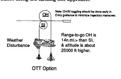
After STS-5, HAC could be flown with the different options we are used to see . Overhead or Straight-In HAC; and Nominal Entry Point (7Nm in final) or Minimal Entry Point (4Nm in final)
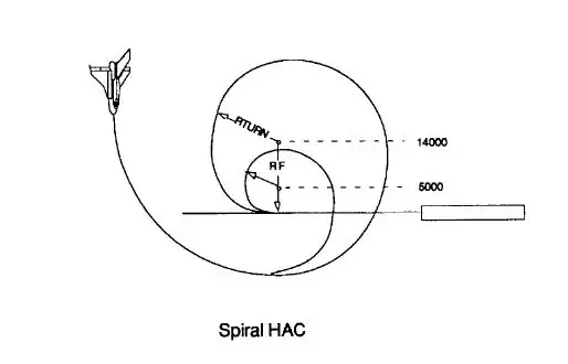
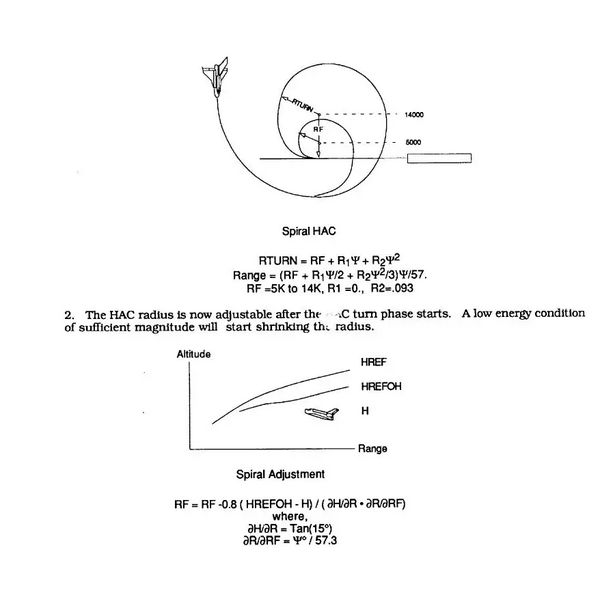
Another option called - final radius shrinking - is included in that TAEM guidance version. It allows the final HAC radius (2.3 Nm) to decrease up to 0.8 Nm if we are low during the HAC.
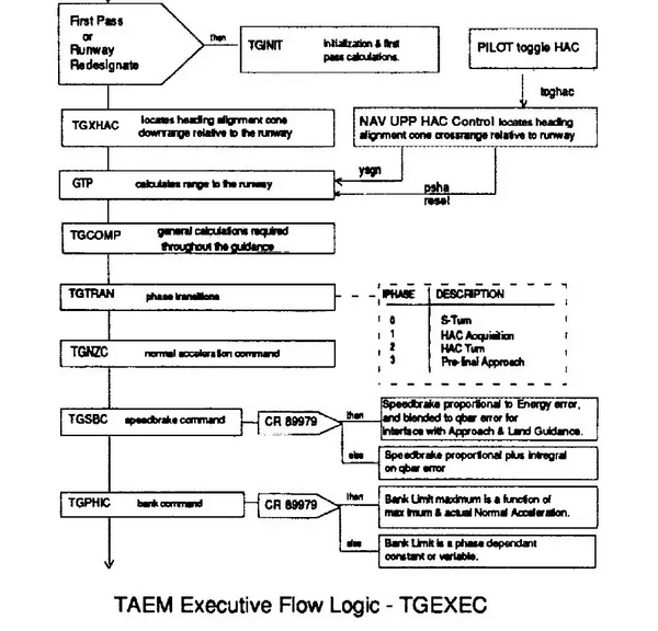
The whole logic is organized through several functions that are called during all the TAEM phase at a rate between 160 and 980ms. It ends at 10000 feet (Approach and Landing interface) where the Auto Land logic kicks in (quite the same logic with tighter gains).
Let's go briefly through each functions. The first function that is not mentionned is a frame coordinate converter from a Greenwhich frame into a runway centered frame.
TAEM
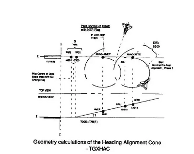
1) TGXHAC
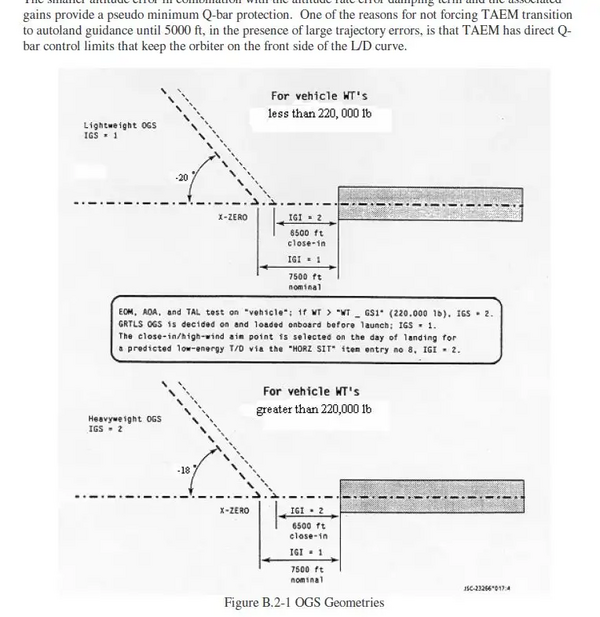
It is the initial TAEM computation where the HAC is defined following what we choose in the Spec 50 display (Runway / Overhead or Straight-In / NEP or MEP / etc) Aim point is also taken into account (7500 feet or 6500 feet)
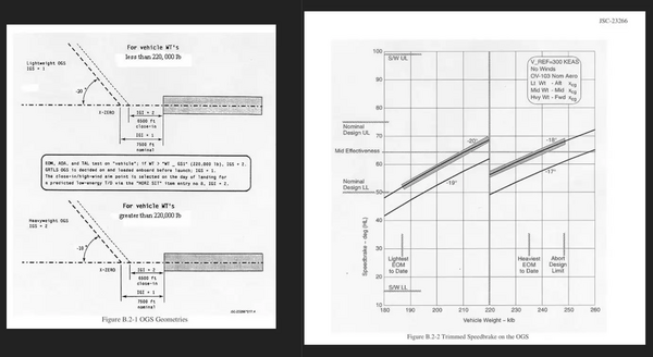
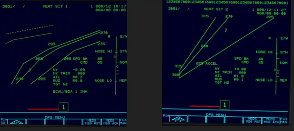
Another important factor that is calculated there is the final glideslope value for the A/L final path (starting at 10000 feet / 6Nm). It can be either 18° for a heavy weight (more than 220000 lbs) or 20° for a lighter Shuttle. That was changed later in the STS program to take into account the nominal mid-value for Speedbrake effectiveness (65°). That slope combination was then choosen.
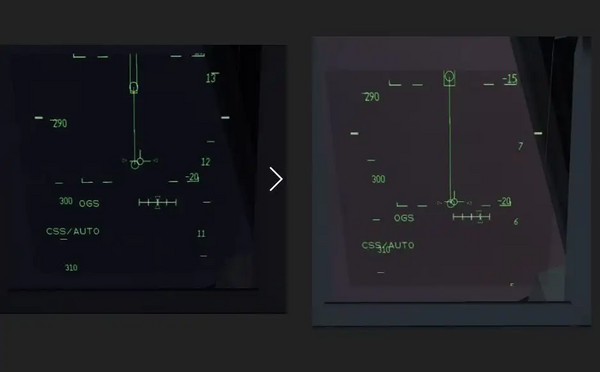
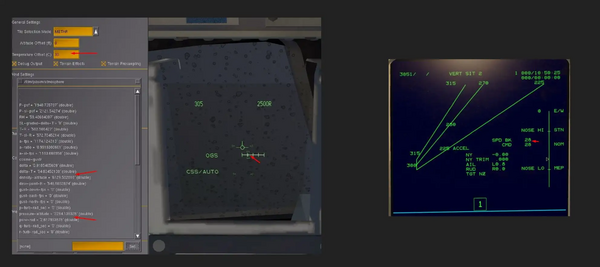
In the november 2024 dev branch, we can clearly see it now at Approach/Landing Interface in the HUD and PFD glideslope deviation. Left HUD for Heavy / Right for Light
2) GTP (Ground Track Computations)
The distance to the runway is computed in that function.
- Left and Center Picture (Before and into the HAC): The range to go is the sum of the distance to be flown while aligning with the HAC entry point(ARCAC), the distance to be flown to that tangent WP1 (RTAN), the distance to be flown into the HAC up to the threshold (RPRED2)
- Right picture: Once close enough to the final runway course, distance forecasted becomes a direct distance to the runway threshold.
3) TGCOMP (General Computations)
All the computations for reference parameters are done there.
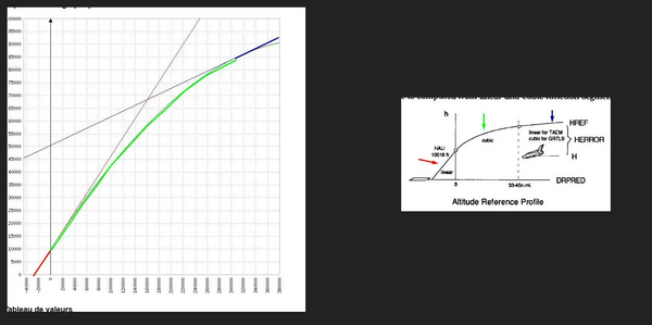
- The Altitude reference
A mix between linear and cubic segments. Up to 40 Nmish in blue, a low slope linear profile (6° ish of slope) Between A/L interface ( 6Nm) and 40 Nm, the green cubic segment where the slope increases up to the final Gamma targeted (18/20°) At A/L interface, the red linear segment for final slope.
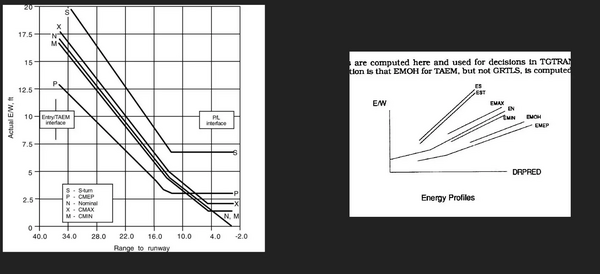
- The Specific Energy reference
That allows to shape the Nominal Energy path based on the True Airspeed and Altitude. S-turn / Nominal / Low Energy boundaries.
Left picture is the Energy lines I took as a reference (closer to the latest Energy profiles flown in the later part of STS program ) Right picture shows that those lines are "just" some linear functions with some breakpoints here and there.
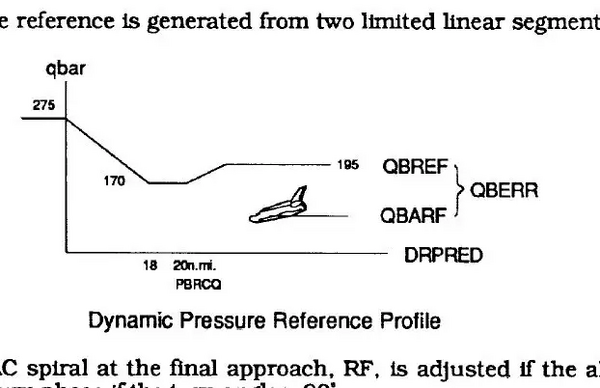
- Dynamic Pressure Reference Profile
It is basically the EAS targeted.
I adjusted it also to be closer to the latest QBAR profile flown (a tad higher, 305 psf targeted at A/L ie. 300 kts instead of 275 kts) It will be coherent with the EAS visible in the Vert Traj display.
Another small logic for Low Energy handling: HAC radius shrinking.
The final HAC radius (past 90° into the HAC) is 14000 feet (2.3 Nm). In case of Low Energy once into the HAC and before the 90° HAC angle to go, the final radius will shrink depending on how Low we are in Potential Energy (up to a final radius of 5000 feet). Basically, it means to be 4000 feet ish low on the glidepath once into the HAC.
An example below. Right picture: Nominal energy situation (final radius of 2.2Nm). Left picture: Slightly off nominal energy situation, HAC final radius shrinked to 1.8 Nm and Shuttle was smoothly brought back on the glide.
4) TGTRAN (Transition between TAEM phases)
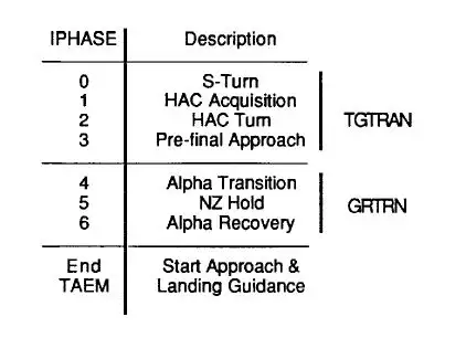
Here is handled the boundaries between the different part of the TAEM and Autoland (Acquisition / HAC / Pre final / Outer Glide Slope / etc) It works like a big Lego, and it will be easy for example to link it later to the RTLS logic with the phases 4 to 6.
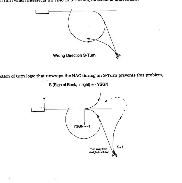
The S-Turns are also commanded in that function for example. A sanity check is done to turn away from the HAC. Once the Total Energy is closed to the Nominal one, IPHASE 0 is exited and we go back to the Acquisition logic (IPHASE 1).
5) TGNZC (Nz Commanded)
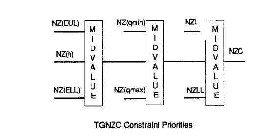
The output for the Pitch AP is done there, under the form of a radial acceleration that will be converted later in to a pitch rate and sent into the AP loop. All the functions calculated in the TGCOMP will be used there to limit that commanded Nz (NZC). MIDVALUE function is like a Nasal clamp function.
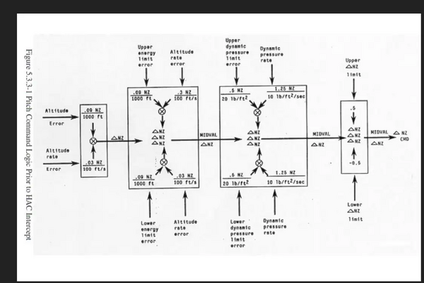
The first NZC computed is for the altitude error, then it goes through an energy error check, then QBAR, and finally a Max Nz filter to clamp the NZC between -0.5 g and +0.5g.
An example. If we are low: positive NZC computed to Pitch Up and come back to the reference altitude. If we are high on energy, a less positive NZC is then outputted to not go too high on energy. If we are too close to QBAR boundaries, NZC is adjusted to stay away from a hazardous aerodynamical pressure condition. Finaly, if we are approaching the max radial G's tolerated, the NZC is limited again to avoid breaking the wings. A quite strong and intricated pitch command loop.
Pitch channel
The TAEM pitch command loop is based on a commanded radial acceleration (NZC) converted into a pitch rate which is sent to the AP loop for the correct elevon deflection. Gains and refresh rate depends on TAEM and Autoland phases. Everything is filtered several times to have some stable outputs.
- Delta Nz commanded is based on the altitude and altitude rate error ( glidepath deviation).
- It goes then through an Energy filter to avoid to be too high or low on energy ( right ladder on MM 305)
- Next filter is a dynamic pressure one to avoid over/underspeed situations.
- Last filter is a Pitch Nz limit (0.5 g) to avoid to break the wings (2g for a 60° of bank turn plus 0.5g for the max pitch commanded ----> 2.5g max for structural considerations)
6) TGSBC (Speedbraked Commanded)
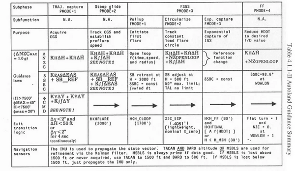
It handles the SB logic. SB setting is fixed to 65° until Subsonic. In subsonic, position commanded is a function of reference Energy and Qbar errors until final where the logic is blended into a QBAR error only up to 3000 feet. From there, a fix setting is commanded for Pre-Flare (Highlighted in the second page there: [3]). That replicates with a great accuracy the original speedbrake logic; fixed setting above Mach 1 (65°) and Energy/Qbar modulation in Subsonic. Once in final, speedbrakes will control the EAS error (300 kt targeted on Outer Glide Slope).
Small interesting points
- Function takes into account the rate limitation depending on the number of hydraulic systems operational.
If more than one system is op, SB opening rate is 5°/s and closing rate is 10°/s If just one system is op, SB opening and closing rate is 5°/S
- At 3000 feet, there is a first SB retract that takes into account many parameters explained page 2 of that topic: [url]https://forum.flightgear.org/viewtopic.php?f=87&t=38777&start=15[/url]
The complete logic page 73 (4-4) of that Handbook: [4]. Another parameterwas added, the Altitude Density variation which is a function of the ISA deviation. High ISA deviation leads to a thiner atmoshpere and a longer flare forecasted, hence a higher SB setting to avoid that over energy situation (and Vice-Versa).
An example there with an ISA deviation of 30 °. Density altitude is 6129 feet and pressure one is 2264 feet (120ft in addition for every degrees above ISA) That gives a SB retract of 28° instead of 15° with ISA 0
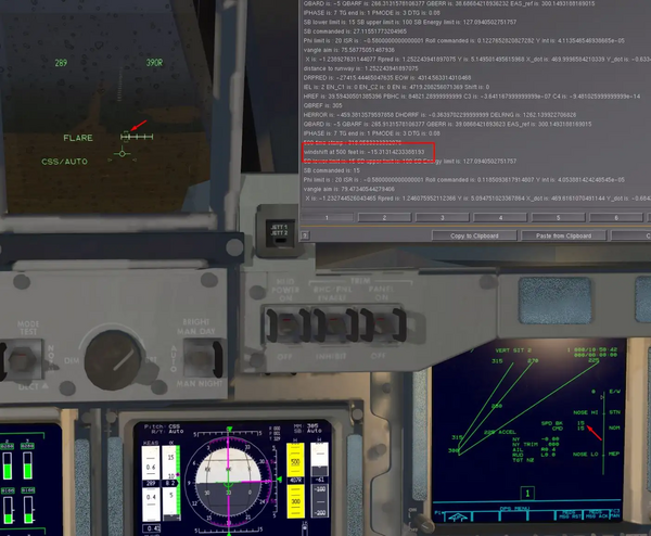
- At 500 feet, the windshift between 3000 and 500 feet is taken into account to adjust one last time the SB position.
That is useful in case of gusty conditions with some late wind changes close to the ground.
An example with a stormy and gusty day (up to 30kt). We lost 15 kt of effective wind since we have past 3000 feet AGL. That is some additional tailwind then and the SB will retract from 23 to 15° to take into account that sudden loss of lift caused by the windshear in order to avoid a hazardous sink rate.
7)TGPHIC (Bank commanded)
Here is done the bank commanded sent to the AP. It depends on the Phase we are in.
From Left to Right.
- IPHASE 0 (S-turn): A constant bank is commanded away from the HAC
- IPHASE 1 (HAC acquisition): A bank proportionnal to the delta azimuth (DPSAC) with the WP1 is commanded (2.5 * delta azimuth)
- IPHASE 2 (In HAC): A bank proportionnal to the the HAC cross range and radial velocity is commanded.
- IPHASE 3 (Pre Final): A bank proportionnal to the final axis cross range / cross range variation /cross range integral is commanded.
For the Autoland phases , it is similar to the Pre Final with different Gains.
From TAEM to Approach/Autoland handover
Landing site threshold coordinates need to be very precise for an autoland. They have been adjusted for KSC/VBG/EDW/ZZA/FMI/IPC/HAO/JDG/KEF/YQX/PAR/INN so far.
At 10000 feet, the TAEM logic is ended and Autoland logic kicks in. It is fairly similar to the TAEM one, with tighter deadbands and additionnal closed loop guidances for the last part (flare,...)
Three parts: Outer Glideslope tracking up to 2000 feet (blue) / Circular pull up flare to decrease the glideslope from 19°ish up to 1.5° (red) / 1.5° Inner Glide Slope and final flare (green)
- Outer Glide Slope tracking.
Either 18° or 20° depending of the weight. Aim point will also slightly modified the downrange and final flare
- Flare and Inner Glide Slope intercept
At 2000 feet, a 1.3gish pull up is commanded to transition from the steep glideslope to a shallower one (combination of open and closed loops). An exponential decay to the inner glide slope allows a smooth transition during that pull up maneuver. Aim is to have at least 5 seconds on the 1.5° slope before the final flare.
- Final Flare
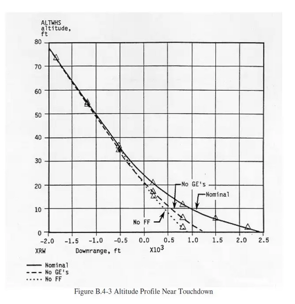
At 80 feet QFE, another pull up is commanded to decrease the rate of descent. Aim is to land 2500 feet past the runway threshold. There are however some dispersions due to winds, ground effect, and some unforseen parameters. The guidance is quite resilient for a wide range of situations and should be able to bring down safely the Orbiter not far from the targeted touchdown zone.
More time to watch the sunset while autopilot is on.
