Primary flight display
A primary flight display or PFD is a modern aircraft instrument dedicated to flight information. Much like multi-function displays, primary flight displays are built around an LCD or CRT display device. Representations of older six pack or "steam gauge" instruments are combined on one compact display, simplifying pilot workflow and streamlining cockpit layouts.
Most airliners built since the 1980s — as well as many business jets and an increasing number of newer general aviation aircraft — have glass cockpits equipped with primary flight and multi-function displays.
Mechanical gauges have not been completely eliminated from the cockpit with the onset of the PFD; they are retained for backup purposes in the event of total electrical failure.
Layout
Note: Not all described functions are implented in FlightGear (yet).
The details of the display layout on a primary flight display can vary enormously. However, some general observations can be made that apply to the great majority of PFDs.
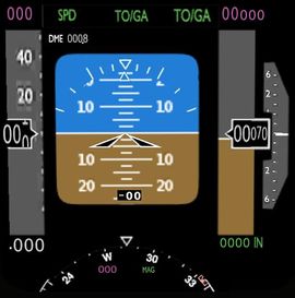
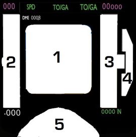
The center of the PFD usually contains an attitude indicator, which gives the pilot information about the aircraft's pitch and roll characteristics, and the orientation of the aircraft with respect to the horizon. Other information that may or may not appear on or about the attitude indicator can include the stall angle, a runway diagram, ILS localizer and glide-path “needles”, and so on. Unlike mechanical instruments, this information can be dynamically updated as required; the stall angle, for example, can be adjusted in real time to reflect the calculated critical angle of attack of the aircraft in its current configuration (airspeed, etc.). The PFD may also show an indicator of the aircraft's future path (over the next few seconds), as calculated by onboard computers, making it easier for pilots to anticipate aircraft movements and reactions.
To the left and right of the attitude indicator are usually the airspeed and altitude indicators, respectively. The airspeed indicator displays the speed of the aircraft in knots, while the altitude indicator displays the aircraft's altitude above sea level (MSL).
The vertical speed indicator, usually next to the altitude indicator, indicates to the pilot how fast the aircraft is ascending or descending, or the rate at which the altitude changes. This is usually represented with numbers in "thousands of feet per minute." For example, a measurement of "+2" indicates an ascent of 2000 feet per minute, while a measurement of "-1.5" indicates a descent of 1500 feet per minute. There may also be a simulated needle showing the general direction and magnitude of vertical movement.
At the bottom of the PFD is the heading display, which shows the pilot the magnetic heading of the aircraft. This functions much like a standard magnetic heading indicator, turning as required. Often this part of the display shows not only the current heading, but also the current track (actual path over the ground), current heading setting on the autopilot, and other indicators.
Other information displayed on the PFD includes navigational marker information, bugs (to control the autopilot), ILS glideslope indicators, course deviation indicators, altitude indicator QFE settings, and much more.

