Howto:Animate gear scissors using the tracking animation
A locked-track animation is an animation that can do exactly the same thing as the Locked Track constraint available in Blender, and it can also be used to simulate simple inverse kinematic systems consisting of two bones connected with a revolute joint (also known as a hinge).
Blender
If you get used to Blender its a really powerful tool (I have problems if trying to work with other modelling programs :P) and with using the right scripts it gets a very neat tool for creating models for FlightGear. For example for a gear scissor just add an armature with two bones, add an inverse kinematic (IK) constraint to the second bone and attach an element of the scissor to each bone, and you are done. You can watch the animation in Blender and using an exporter script now it is possible to watch exactly the same animation inside FlightGear. You do not need to guess any coordinates/axes/etc. and if you modify and object you just have to export it again, without manually modifying the animation XML file.
There are (currently) only two axes required. The lock-axis and the track-axis. They should be orthogonal, as the rotation is only possible round the lock-axis. Internally the track-axis is always orthonormalized to the lock-axis, as calculations always are performed in the plane normal to the lock-axis.
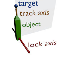
Initial pose
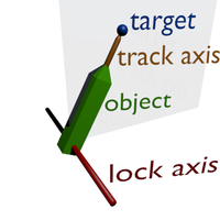
The target has moved and the
locked-trackanimation ensures the object still points at the target (with thetrack-axis)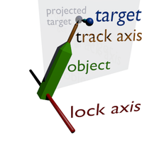
The target is projected into the plane defined by the object center and the
lock-axisbefore thelocked-trackanimation is applied.
For example, you can use the normal rotate animation to rotate the main strut. Every attached hydraulic cylinder, link, etc. is then animated using the
locked-track animation. For a hydraulic cylinder the piston and the cylinder housing each are animated using a locked-track animation tracking each other. For a gear scissor, a locked-track animation tracks from a point attached to the strut to a point on the axis. Two objects can be attached to the animation, allowing to animate a scissor. (The object and the slave object, are rotated such that the exactly fill the space between the two attachment points of the scissor).
For the animation a center point and an orientation (axis) are required to calculate the location and orientation of the rotation. Think of the center as the location of the hinge somewhere in space and of the axis as the actual orientation of the hinge. You can now either specify the position of the hinge and the orientation of its axis or (the alternate form) two points on the axis of the hinge, which are then used to calculate the center and orientation of the hinge. (If you use the alternate form the center and axis are automatically calculated from the two given points).
There is no rotation that you can not describe with a single axis given by its xyz coordinates.
Slave center/object
The slave-center specifies the location of the revolute joint. Optionally an object can be specified using slave-name, which will be attached to the animated object and also tracks to the target object.
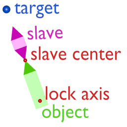
Initial pose
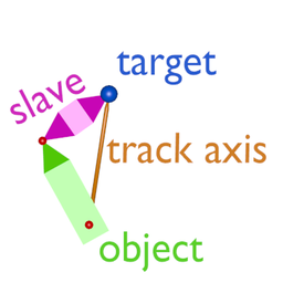
The target has moved and the
locked-trackanimation ensures thetrack-axisstill points at the target. Theobjectand theslave-objectare rotated such that the available space is exactly filled (aka scissor animation).
Examples
Basic usage (Same behaviour as Locked Track constraint in Blender):
<?xml version="1.0" encoding="utf8"?>
<PropertyList>
  <animation>
    <type>locked-track</type>

    <object-name>ADS Arm - Fuselage.r</object-name>
    <center>
      <x-m>4.9</x-m>
      <y-m>1.47</y-m>
      <z-m>3.82</z-m>
    </center>
    <lock-axis>
      <x>0</x>
      <y>1</y>
      <z>0</z>
    </lock-axis>
    <track-axis>
      <x>0.75</x>
      <y>0</y>
      <z>-0.662</z>
    </track-axis>

    <target-name>ADS Arm - Ramp.r</target-name>
    <target-center>
      <x-m>7.969</x-m>
      <y-m>1.475</y-m>
      <z-m>1.11</z-m>
    </target-center>

  </animation>
</PropertyList>
Gear scissor/link with joint (In Blender the same animation can be achieved using an armature with two bones and an IK constraint applied to the second bone, tracking the target object. The animated object is attached to the first bone and the slave object to the second bone.):
<?xml version="1.0" encoding="utf8"?>
<PropertyList>
  <animation>
    <type>locked-track</type>

    <object-name>NLG Front Door</object-name>
    <center>
      <x-m>-11.52</x-m>
      <y-m>0</y-m>
      <z-m>1.13</z-m>
    </center>
    <lock-axis>
      <x>0</x>
      <y>1</y>
      <z>0</z>
    </lock-axis>
    <track-axis>
      <x>1</x>
      <y>0</y>
      <z>0</z>
    </track-axis>

    <target-name>NLG-Strut</target-name>
    <target-center>
      <x-m>-9.9</x-m>
      <y-m>0</y-m>
      <z-m>1.13</z-m>
    </target-center>

    <slave-name>NLG Front Door Arm</slave-name>
    <slave-center>
      <x-m>-11.335</x-m>
      <y-m>0</y-m>
      <z-m>1.076</z-m>
    </slave-center>
  </animation>
</PropertyList>
Use a condition to disable tracking (and optionally apply specify a rotation being applied while disabled):
<?xml version="1.0" encoding="utf8"?>
<PropertyList>
  <animation>
    <type>locked-track</type>

    <condition>
      <property>/controls/gear/nose-wheel-steering</property>
    </condition>
    <disabled-rotation-deg>-90</disabled-rotation-deg>

    <object-name>Torque Link Upper Arm</object-name>
    <center>
      <x-m>-9.785</x-m>
      <y-m>0</y-m>
      <z-m>1.04</z-m>
    </center>
    <lock-axis>
      <x>0</x>
      <y>1</y>
      <z>0</z>
    </lock-axis>
    <track-axis>
      <x>0.022</x>
      <y>0</y>
      <z>-1</z>
    </track-axis>

    <target-name>Torque Link Lower Arm</target-name>
    <target-center>
      <x-m>-9.789</x-m>
      <y-m>0</y-m>
      <z-m>0.454</z-m>
    </target-center>

    <slave-center>
      <x-m>-10.033</x-m>
      <y-m>0</y-m>
      <z-m>1.035</z-m>
    </slave-center>
  </animation>
</PropertyList>
Lessons learned
Scissors - with parenting

As seen to right, we have a oleo strut, and a gear leg. The oleo strut has a compression animation which uses a translate animation to move up or down according to gear-compression. There are two torque links - the top is called NLGTorqueLink1 and the bottom NLGTorqueLink2.
The bottom link must be a child of the top link.
After the translation animation, setup a locked track animation on NLGTorqueLink1. The center is the hinge of the top scissor arm, the target is the hinge of the bottom arm, target-name is the oleo strut which is translated. Finally, the slave-name is the bottom scissor arm, and the slave-center is where the two arms meet.
	<animation>
		<type>locked-track</type>
		<object-name>NLGTorqueLink1</object-name> <!-- upper -->
		<center>
		  <x-m>-13.468</x-m>
		  <y-m>-0.006419</y-m>
		  <z-m>-3.34389</z-m>
		</center>
		<lock-axis>
		  <x>0</x>
		  <y>-1</y> <!-- inverting this gives strange results! -->
		  <z>0</z>
		</lock-axis>
		<track-axis> <!-- +- ve doesn't matter -->
		  <x>0.100957</x>
		  <y>0.569667</y>
		  <z>0.001675</z>
		</track-axis>

		<target-name>NLGSlidingTubeAxle</target-name> <!-- oleo strut -->
		<target-center>  <!-- rotation axis of lower -->
		  <x-m>-13.569</x-m>
		  <y-m>-0.004744</y-m>
		  <z-m>-3.91356</z-m>
		</target-center>

		<slave-name>NLGTorqueLink2</slave-name>
		<slave-center>  <!-- middle hinge -->
		  <x-m>-13.2685</x-m>
		  <y-m>-0.005584</y-m>
		  <z-m>-3.67419</z-m>
		</slave-center>
	</animation>
Scissors - without parenting
The same animation can be done without parenting. The way this is animated is as follows:
Each torque link rotates around its base, where it meets the oleo strut / gear leg and is locked on the y-axis. The target position is at the 3D cursor, where both of them meet, and the track axis is the axis between the two centers of rotation of the torque links (about ten degrees off vertical). The target object is the other torque link (number 1 for number 2 and vice versa). The slave-center is the center of rotation for the other torque link.
	<animation>
		<type>locked-track</type>
		<object-name>NLGTorqueLink2</object-name> <!-- lower -->
		<center>
		  <x-m>-13.569</x-m>
		  <y-m>-0.004744</y-m>
		  <z-m>-3.91356</z-m>
		</center>
		<lock-axis>
		  <x>0</x>
		  <y>1</y>
		  <z>0</z>
		</lock-axis>
		<track-axis>
		  <x>0.100955</x>
		  <y>0.569668</y>
		  <z>0.001675</z>
		</track-axis>

		<target-name>NLGTorqueLink1</target-name>
		<target-center>
		  <x-m>-13.2685</x-m>
		  <y-m>-0.005584</y-m>
		  <z-m>-3.67419</z-m>
		</target-center>

		<slave-center> <!-- rotation axis of upper -->
		  <x-m>-13.468</x-m>
		  <y-m>-0.006419</y-m>
		  <z-m>-3.34389</z-m>
		</slave-center>
	</animation>

	<animation>
		<type>locked-track</type>
		<object-name>NLGTorqueLink1</object-name> <!-- upper -->
		<center>
		  <x-m>-13.468</x-m>
		  <y-m>-0.006419</y-m>
		  <z-m>-3.34389</z-m>
		</center>
		<lock-axis>
		  <x>0</x>
		  <y>1</y>
		  <z>0</z>
		</lock-axis>
		<track-axis>
		  <x>-0.100955</x>
		  <y>-0.569668</y>
		  <z>-0.001675</z>
		</track-axis>

		<target-name>NLGTorqueLink2</target-name>
		<target-center>
		  <x-m>-13.2685</x-m>
		  <y-m>-0.005584</y-m>
		  <z-m>-3.67419</z-m>
		</target-center>

		<slave-center> <!-- rotation axis of lower -->
		  <x-m>-13.569</x-m>
		  <y-m>-0.004744</y-m>
		  <z-m>-3.91356</z-m>
		</slave-center>
	</animation>
This is confusing and non-intuitive, to say the least, but works!
3 axis locked-track animation
Sometime is necessary realize the animation to an object with ball joint, is the typical case of a hydraulic jack actuate the opening the landing gear, it is necessary to proceed in two stages, as locked-track animation always needs at least a locked axis.
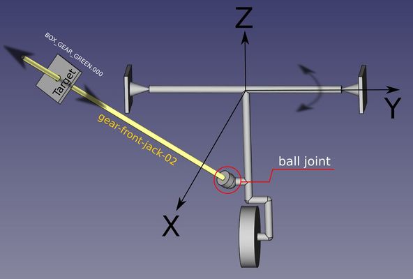
3 axis locked-track animation example.

First locks, for example, the y axis and directs the object to a target object, in this example BOX_GEAR_GREEN.000 with coordinates: target-center. The track-axis is the axis that should point the target:
<?xml version="1.0" encoding="utf8"?>
    <animation>
        <type>locked-track</type>
        <object-name>gear-front-jack-02</object-name>
        <center>
            <x-m>-2.91953</x-m>
            <y-m>-0.06230</y-m>
            <z-m>-1.30829</z-m>
        </center>
        <lock-axis>
            <x>0</x>
            <y>1</y>
            <z>0</z>
        </lock-axis>
        <track-axis>
            <x>1</x>
            <y>-0.23</y>
            <z>0.630</z>
        </track-axis>
        <target-name>BOX_GEAR_GREEN.000</target-name>
        <target-center>
            <x-m>-2.04543</x-m>
            <y-m>-0.23232</y-m>
            <z-m>-0.82533</z-m>
        </target-center>
    </animation>
Then write a second locked-track, which should be put immediately under the first, which locks the x axis. Everything else is equal, as all other references are unchanged.
<?xml version="1.0" encoding="utf8"?>
    <animation>
        <type>locked-track</type>
        <object-name>gear-front-jack-02</object-name>
        <center>
            <x-m>-2.91953</x-m>
            <y-m>-0.06230</y-m>
            <z-m>-1.30829</z-m>
        </center>
        <lock-axis>
            <x>1</x>
            <y>0</y>
            <z>0</z>
        </lock-axis>
        <track-axis>
            <x>1</x>
            <y>-0.23</y>
            <z>0.630</z>
        </track-axis>
        <target-name>BOX_GEAR_GREEN.000</target-name>
        <target-center>
            <x-m>-2.04543</x-m>
            <y-m>-0.23232</y-m>
            <z-m>-0.82533</z-m>
        </target-center>
    </animation>
The track-axis configuration
The track-axis is the real direction of the object that follows the target point. It is not very simple to configure as it also depends on the geometry of the piece. A very simple method for configure the axis direction is define it when the object is in the "rest" position, in essence in the position where the object is in the 3D file. When we activate the animation, even if we have correctly defined the center point and the target point, often the initial position of the object is not what we think is correct. At this point it is necessary to operate by varying the values of the free axes (Remember: the locked axis is the one defined in the lock-axis) until the piece assumes the correct initial position.
Tips
Graphic graph of coordinates of vertices of a line in angular coordinates according to the linear XYZ form
Strangely, the coordinates of the <track-axis> section do not seem to work on the coordinates given in the form: <x1-m> .. </ x1-m> ... <z2-m> .. </ z2-m >. We must give the coordinates in the form <x> ... </ x> ... <z> .. </ z>. To easily convert vertices, you can use the 3D CAD application FreeCAD. You create a line by inserting the two vertices (V1 and V2) and then activating the Bounding Box display, as shown in the figure. The 3 coordinates X, Y, Z can be used directly as x, y and z coordinates. But be careful with the signs.

Coordinates of vertices of a line convert in angular coordinates according to the xyz form.
