Concorde
From wiki.flightgear.org
| Concorde | |
|---|---|
 | |
| Type | Airliner |
| Livery | British Airways |
| Status | Development |
| --aircraft | Concorde |
| Current user rating: 80% (7 votes)
You need to enable Javascript to vote
| |
| Download | |
1 The Aérospatiale-BAC Concorde supersonic transport (SST) was the more successful of the only two supersonic passenger airliners to have ever operated commercially, the Tupolev Tu-144 being the other.
As a result of the type's only crash on 25 July 2000, world economic effects arising from the 9/11 attacks, and other factors, operations ceased on 24 October 2003. The last "retirement" flight occurred on 26 November that year.
The Concorde has been in development for a long time with FG, and the version for FG 1.0.0 has many advanced abilities including ability to control different wing and systems, 3D interior locations, and animations. High altitude flying in FGFS 1.0.0 in the Concorde does not result in the ability to see the curvature of the earth however.
Contents |
Panels & Instrumentation
The Concord-Model comes with 2 panel-versions:
- with 2 “2D”-panels: The "2D-Main" contains only the major System-Controls, independent of the location and or grouping in the real aircraft. In addition it combines some complex functions into simple buttons or switches (e.g. the fuel pumping tasks). This 2D-panel gets supported by only one very “faked” engineering panel (to be reached with “upper S” from the 2D-panel). These 2 “non realistic” panels make it much easier to “get a first feeling”, prior to having to concentrate onto the Concorde unique technicalities.
- and many 3D-panels (Captain, Co-pilot, Center, Overhead, Engineer, Pedestals, etc.). With those panels you may discover the whole wide range of this technical masterpiece.
You can switch between 2D and 3D in the usual manner (menu → View → “Toggle 2D Panel”). In addition the system switches automatically from 2D into 3D if you change the view-direction – and will return to 3D when the view returns to the standard setting.
The following description covers both versions – thus all common instruments are numbered the same in both versions. Instruments not shown in the simple 2D-version are indicated in the description by “no2D”.
The panel pictures show all “Hot-Spots”, i.e. areas in which you can adjust the values by mouse-clicks. Notice that many datum-fields do have up to 8 fields to set. See e.g. the NAV settings (55) in the Autopilot: The most left 2 vertical spots increase/decrease just the most left digit. The second pair the digits 2 and 3 (and overflow into 1), the next pair the first decimal digit, etc.
For a more detailed descriptions and real photos of the cockpit etc. see e.g. http://www.concordesst.com/cockpitsys.html
The 2D-Panels

In the center you see the standard instruments, on top the Autopilot, and on the right the Fuel handling. Especially the Fuel-Handling in the 2D-version is not realistic at all, for “reality” key “Ctrl+E” (and return with the same “Ctrl+E”).
Typing “Uppercase + S” will bring you (after about 10 sec!) to:
The additional 2D-Engineering-Panel:

Because of the very long response-times while switching back and forth we suggest to get used to just moving the angle of view (if e.g. you want to see the engine instruments or similar), the 3D panel then pops up at once!
The 3D-Panels

In addition to the 2D-panel-instrumentation you see here especially the center with the Engine-Controls and to the right (already on the Co-Pilots side) the Gear, Nose and Trim-controls. On top of all is the “Autopilot” or formally the AFCS = “Automated Flight Control System”.
Key “f” if you do not see all instruments on a panel. The amount of displayed instruments is reduced by default, in order to not reduce the frame rate of your PC - “f” cancels these display-limitation.
>>>> Other panels will be shown when unique tasks are described <<<<<
Description of the Basic-Instruments
Some instruments are not available in the 2D-panel. Those you find by keying “upper S” to look onto the 2D-engineering panel. But that switch takes very long. So I suggest to use 2D at the beginning. When the wanted instrument is not there just change the view-point and the 3D-panel pops up. And if it is not there use CTRL+E to go to the 3D-Engineering panel. Whenever you reset the view-point the 2D-panel will again pop into the foreground (unless you disable that be selecting "Menu --> View --> Toggle 2D Panel”.
All instruments in the pictures are labeled with numbers within a light circle, except the AFCS buttons which are referred to by there visible big inscription. In the description the numbers are referred to by (nn). (no2D) means that there is no equivalent in 2D-panels.
The picture of the 3D-panel shows only the left and the center part of the main panel. The right part is just a replication of the Pilot-instruments for the Co-Pilot, those instruments would carry the same numbers.
- Not yet used
- ATT-INS 1/2 (no2D): (Not yet functional)
- COMP 1/2 (no2D): (Not yet functional)
- DEV 1/2 (no2D): Switches (18) to display either NAV1 or NAV2
- NAV INS 1/2 (no2D): Switches between left/right INS (Inertial Navigation System) on the center pedestal
- G-meter + AoA (angle of attack) (no2D): The index at the left shows the actual “G”-forces (forces that occur when accelerating a body), the white bar on the right the actual AoA.
- Warnings:
- TERRAIN:
- excessive rate of descent below 2500 ft.
- excessive closure rate with ground.
- loss of altitude below 700 ft, after takeoff or go-around.
- gear not locked below 500 ft, or nose not down below 200 ft on approach
- Nose not down at Touch-Down
- M/CG: Center of Gravity is out of tolerance (see (20) and chapter "Balancing by Fuel-Pumping")
- TYRE: Tire pressure at fault (tyre=BR == tire=Am)
- TERRAIN:
- CAS (Calibrated Airspeed in Knots): The white pointer indicates the actual CAS analog (and digital), the yellow one indicates the maximum allowed CAS (according to altitude, density, temperature, etc.). The yellow light at the upper left corner is on when the autopilot (IA) is acquiring a CAS.
- 8a (no2D): A backup for (8)
- 8b: The same as (8), but in Mach. In addition there are 2 moving yellow markers indicating the minimum and maximum Mach numbers according to the M/CG (31).
- DME: Distance in miles to VOR/ILS 1 and 2
- TAS: Actual airspeed over terrain in kt/h
- VOR 1/2-pointer, direct pointing into the directions of the VOR's, set in (55) and (64) (see also The VOR/INS/ILS System). (The yellow pointer for VOR1, the white pointer for VOR2)
- AP-Warning (no2D):
- Instrument failure
- abnormal pitch
- abnormal AoA (Angle of Attack, pitch)
- AT-Warning if:
- altitude acquired active without auto-throttle
- glide or auto-land active without auto-throttle
- airspeed indicator out of order
- ILS: ILS signal missing
- Landing Display:
- LAND 2 : Landing with category 2 capabilities:
- Flight controls in an electrical mode.
- One autopilot engaged in LAND mode.
- The flare light test successful.
- At least one landing display serviceable.
- At least one auto-throttle engaged in IAS ACQ mode
- LAND 3 : Landing with category 3 capabilities:
- All LAND 2 capabilities (see above), plus:
- At least one flight director engaged.
- Green/yellow hydraulic system pressure correct.
- Both AFCS VOR LOC selectors at the same course.
- Electrical generation split.
- DH on signals the aircraft being below the “decisions height” set in (23)
- LAND 2 : Landing with category 2 capabilities:
- Lamp-Test (no2D)
- Attitude Indicator: Indicates the attitude of the aircraft compared to the real horizon. In addition:
- DH will light when below Decision Height set in (23)
- ATT will light if attitude is excessive or data might not be trustable
- if the autopilot FD is activated it will show a horizontal and a vertical bar indicating the airplane position relative to the ILS-Glide-Slope
- You can adjust the artificial plane by rotating the dial at the lower center.
- Gyro-Compass with integrated VOR, INS, and ILS indicators (see The VOR/INS/ILS System)
- Horizontal Slip Indicator
- Vertical-Speed-Indicator: The scale is in 1.000 FPM (Feet Per Minute). The yellow marker shows the actual FPM, the white one the preselected value. In the center of both, upper and lower half's, there are the “hot points” for preselecting when e.g. autopilot (VS) is active.
- R NAV (no2D): Indicates when the DME signal of the VOR/ILS is usable. The light on the pilot-side indicates for DEV1, the one on the co-pilots side DEV2.
- WX RDR: <<<<To Be Defined>>>> (Radar???)
- Altitude to Ground: Indicates the altitude from ground up 2.500 ft. With the knob in the lower left you define the decision height (see (15 + 17).
- A backup for (17) (no2D)
- Altimeter: The digital Indicator shows the Height in 1000 ft, the analog pointer shows the values in between. With the knob in the lower left corner you adjust the static pressure. The yellow light at the upper left corner is on when the autopilot is acquiring an altitude (AA).
- FD1 / FD2 switch (no2D) displays the ADF signal inside the Attitude Indicator (17)
- ADF 1/2-pointer, directly pointing towards the ADF's, set in “menu → Concorde → Radio”. The yellow one is for ADF1, the white one for ADF2.
- Chronometer without special functions.
- Vertical Speed: When the Autopilot initiates a descent it will set the descent typically to the standard 750 FPM. After activating (VS) you can vary that climb/descent between +/- 6.000 FPM (see also (20))
- INS (Inertial Navigation System) (no2D): Warning if one of the INS-systems is not aligned or in failure. (see The VOR/INS/ILS System)
- M/CG (Mach/Center of Gravity) : Indicating the actual balance of the plane. (see Balancing by Fuel-Pumping)
- ILS-Marker:
- White + sound 3000 Hz: Aircraft over airway marker beacon
- Amber + sound 1300 Hz: Aircraft over a terminal middle marker beacon
- Blue + sound 400 Hz: Aircraft over a terminal outer marker beacon
- Test button (for bulbs)
- Status-Display: From Top to button
- CTY: if blinking indicates afterburner activated
- T/O: “Take-Off” engine rating
- CLB: “Climb” engine rating
- CRS: “Cruise” engine rating
- Brakes Control: show the applied forces
- BRAKES FAIL (no2D): no normal breaks available (green hydraulics missing)
- BRAKES EMERG (no2D): Parking or Emergency brake problems (no green hydraulic)
- T/O MONITOR: Activate before TakeOff to allow engines to operate beyond N2 (see (40))
- AFCS-MODE: Dims the “on”-lights inside the AFCS-control-buttons
- TOTAL CONTENT in kg
- Power management:
- GO (green): Indicates that the secondary nozzle buckets are positioned within limits, the CON light is off and the set bug values of P7 and FUEL FLOW have been achieved, and the ENG 4 T/O N1 LIMITER has returned to NORMAL position. It also allows you to exceed the N2-limits – armed by (37).
- CON (Yellow):
- with no decrease in N2, indicates loss of reheat thrust.
- with reverse thrust selected indicates that the primary nozzle is greater than 15%
- REV (blue):
- FLASHING - indicates that the reverser-buckets are in transit (to toggle: “ctrl+B”)
- ON - indicates that the buckets are closed (reverser active)
- OFF - indicates that the buckets are within the forward thrust range
- N2 instruments: Percentage of the maximum RPM (revolutions per minute). 100% may be exceeded if Takeoff Monitor (37) is active (Compare (40) green).
- N1 instruments: Percentage of the maximum low pressure spool
- FF instruments: Fuel Flow in “kg/h * 1000”, in analog and digital. With the knob at the lower right you can adjust the indicator bug in the scale and also the digital indicator to vary and indicate the required take-off value
- EGT instruments: Temperature in the jet pipe, in analog and digital
- Area instruments: Primary nozzle exhaust gas discharge area in %.
- when in the white area Reheat/Afterburner operate correct
- the extra yellow area at Eng.#4 indicates correct Reheat/Afterburner operation below 60 kt/h
- The yellow light on the top left indicates that the Reheat/Afterburner selector is not off
- WHEEL: Break overheat
- GEAR up/down switch (see also the control (52))
- Nose Wheel: Nose steering without hydraulic support
- NOSE operation: Clicking on the top marker of the lever lowers the Nose, and reverse. This is needed during Taxiing and Start-/Landing, because otherwise the Concord crew can hardly see the Taxi- and runways. In addition the Nose acts like flaps, by adding drag.
- Visor & Nose indicator (watch that the Hot-Spots for raising/lowering the nose are on the lever – not on the buttons!)
- Windshield wiper
- Gear controls (see switch (47)): The 4 gears are: Left, Nose, Right, and "Tail-protection without an unique door"
- Upper 3 yellow indicators: Doors in transit/unlocked
- Middle 4 red indicators: Gear in transit/unlocked
- Lower 4 green indicators: Gears locked in down position
- All off: Gears and Doors locked in upper position
- Trim-Indicator: For supersonic flights you should not use “Elevator-Trimming”, because that increases drag – instead you must balance the plane by pumping fuel back and force (see chapter balancing)
- AUTO-LAND warning:
- 100 ft above ground → ILS Glide-Slope not reliable
- excessive ILS deviation below 200 ft for Localizer
- excessive ILS deviation between 200 and 100 ft for Glideslope
- ILS failure below 200 ft for Localizer
- ILS failure between 200 and 75 ft for Glideslope
- missing auto-throttle below 600 ft.
- NAV1: This is usually set to the ILS-frequency for Landing. Set the radial for it at (59). (see also The VOR/INS/ILS System)
- RAD / INS: Switches ONLY THE DISPLAYS between the common navigation (VOR) and the “Inertial Navigation System”. To navigate accordingly see The VOR/INS/ILS System
- Speed preset: The selector for the wanted speed (if control is given to the Autopilot). Be aware that with the selector you just define which speed you want to acquire next – the autopilot will execute that command only after you activated IA (see also AFCS (Automated Flight Control System)) – thus you can predefine your needs well in advance.
- Radial TH: The radial setting for flying with autopilot TH (True (magnetic) Heading). This one moves the little yellow marker on the scale inside the Pilot-Gyro-Compass (18), when the instrument is not switched to INS or NAV2 (see (4) and (56)).
- Radial NAV1: The radial setting for NAV1 (55), this will turn the ILS-Indicators inside the (18), if DEV1 is selected ((4) and (56)).
- Radial TH: The radial setting for flying with autopilot TH (True (magnetic) Heading). This one moves the little yellow marker on the scale inside the Co-pilot-Gyro-Compass (not shown).
- Radial NAV2: The radial setting for NAV2 (64), this will turn the ILS-Indicators inside the Co-pilot-Gyro-Compass(not shown).
- Altitude preset: The selector for the wanted altitude if flying under autopilot control. To acquire this set altitude activate AA.
- RAD / INS switch for the Co-pilot (compare (56))
- NAV2: Is located on the Co-pilots side. It is usually used for the VOR-navigation.
AFCS (Automated Flight Control System)
The AFCS is the panel between the main-panel and the front-windshield. It is what you usually call the “Autopilot”. In the following you will find only a short explanation – if you are interested in more details, see: http://www.concordesst.com/autopilot.html (but be aware that there may be some functions described, which are not (yet) implemented in the model).
AP & FD (Autopilot & Flight-Director)
- Both have two independent systems, but only both FD's are engaged to supervise each other.
- Activate AP as soon as you have established a steady climb after Take Off. That will also activate HH + PH, thus enabling you to hold the runway-heading and climb-rate after start. Only one AP can be activated – be sure you activate the left one when the pilot is flying or the right one when the copilot is flying!
- If AP gets activated after FD it will not activate PH and/or HH
- If FD gets activated it will automatically activate PH (if not yet active) and the NAV indicators inside the Horizon (17). You should always activate both FD-switches: One will be acting onto the pilots instruments, the other onto the copilot's instruments.
AP Speed-Control
- AT = Auto-Throttle: Needs to be activated if you want to fly a predefined speed. There are 2 independent Auto-Throttle systems which supervise each other and automatically take over in case of trouble. So you should always activate both at the same time.
- MH = Mach Hold: Will hold the actual Mach at the moment when MH is pushed. Because of the drastically changing relation of Mach to CAS, you should use it for cruise control, but not during significant changes in altitude.
- IH = Indicated Airspeed Hold: Will hold the actual CAS (calibrated Indicated Airspeed) at the moment when IH is pushed. Be aware, that a constant CAS will result in very different Ground-Speeds at different altitudes! Also: During supersonic flying your CAS will be above 500 kt/h - if you try to descent with that speed you might find yourself on the ground very fast - broken into pieces!
- IA = Indicated Airspeed Acquire: If IA is activated the Autopilot will try to acquire the Speed predefined in (57). Whenever you change the value in (57) you have to reactivate AP before the plan will follow the new setting.
- For any time-distance Calculations use the TAS indicated at (10).
AP Heading-Control
- IN = Inertial Navigation System Mode: Will hold a straight course to the target set in “Autopilot → Route Manager” or which are set in the Concord own INS-system (center pedestal).
- TH = True Heading: Will follow the Course set by the Control-Setting (58), see the small widget inside the (18) compass-scale. Whenever you change that widget (and TH is active) the plane will follow immediately.
- Hl = Heading Hold: Holds the actual magnetic Heading, independent of any presets
- TU = Turbulence Mode: Will automatically smoothen down heavy attacks of turbulences by slowing down the automatic-reactions.
- BB = Back Beam: Sets the course to 180 degrees of the VOR/ILS-Beam. (is not yet functional)
- VL = VOR1 Lock: Sets the heading according to the preselected radial in (59). The pure selection will be indicated by an underlining light, the button itself will be lit when on the radial.
- GA = Go Around: Terminates any ILS-approach immediately and initiates a Go Around. This may be caused by a malfunctions (see above) or by pushing the throttle fully forward while on the glide-slope.
AP Altitude Control
ATTANTION: If something is scontrolled by pitch, that can lead to stall or overspeed, if not watched by a human being!
- PH = Pitch Hold: Will hold the Pitch as predefined in “Autopilot → Autopilot Setting” or indicated in (17)
- MP = Mach Hold per Pitch: Means the pitch will be adjusted to hold the speed in Mach – in opposite to the usual controlling of the CAS via IP. Remember: During climb/descent the relation between Mach and CAS may change drastically!
- CL = Max Climb rate hold by variable pitch
- IP = Indicated Airspeed hold by variable pitch
- LA = Auto-Land: Did not yet work reliable for me. Should prime the VL and GL mode to follow the glide-slope when intercepted. When at interception and the AT is not engaged the AUTOLAND will start continuous flashing! Autoland is known NOT to operate correct “down to 0” at all destination airports - you better UNcheck “menu → Concorde → autopilot → Nav accurate until 0..” .
- GL = Glideslope: Will follow the ILS Glideslope defined by NAV1, if the NAV1-Lock is active (see VL under Heading options).
- WARNING: If you activate GL while the plane is far off the Glideslope, then the plane will very rapidly try to assume the right slope - even if that means a very steep climb or descent (or even crash!)!
- CR = Max Cruise: Will reduce to Max Speed and then engages MH (Mach Hold))
- VS = Vertical Speed Hold: Holds the actual FPM when the button is pressed
- AH = Altitude hold: Holds the actual Altitude when the button is pressed
- AA = Altitude Acquired: Acquires the Altitude defined with (62), then activates AH. Whenever you change AA you have to reactivate it again (even if active already!) before the plan will follow the new setting.
The VOR/INS/ILS System
In the Concord there are 3 independent navigation-structures with the following components:
- 2 NAV-Radios: Each having a “selected” and a “standby” frequency as usual, in basic FlightGear they are called NAV1 and NAV2, in the Concorde they are defined as DEV 1 and DEV2:
- Per default NAV1 is switched to be used by the pilot, NAV2 to the copilot
- Only NAV1 can be used for VOR/ILS tracking (as long as the center pedestal is not designed to switch the NAV's).
- The easiest way to set these radios is via “menu-bar → Concord → Radio” (which is the same as the standard FGFS “menu-bar → Equipment → Radio Setting”, but has 2 ADF settings, instead of only 1 in the standard FGFS)
- You can switch the (selected) frequencies also by (55) for NAV-1 and (64) for NAV-2
- and set the wanted radial via (59) for NAV-1 and (61) for NAV-2
- 1 INS (Inertial Navigation System). You can set the so called “waypoints”
- via the standard FGFS “menu-bar → Autopilot → Route Manager”
- or via the 2 Concord unique input panels on the center pedestal (not yet described here)
- 2 VOR Pointers (11), one for the pilot and one for the copilot, both pointing to both tuned in VOR-transmitter-stations (if they are in range!). On both pointer-instruments the yellow pointer points to VOR-1, the one with the white arrow to VOR-2.
- 4 Displays: 2 inside the Gyros (18) and 2 more in the Attitude Indicator (17) when FD is active. 2 of those are on the pilot side, the other 2 on the copilot side. To enable both pilots to select any of the two NAV's in their Gyro, there are several switches:
- To DISPLAY: With switch (56) you define which type navigation will be displayed inside the Gyros (18) and/or (17). Then you define with
- switch (4) which NAV (1/2) is displayed
- switch (5) which of the 2 INS (on the pedestal) are displayed
- To ACTIVATE: To actually activate the predefined navigation you have to activate either VL for navigation by VOR, or IN for navigation by way-points.
- To DISPLAY: With switch (56) you define which type navigation will be displayed inside the Gyros (18) and/or (17). Then you define with
- Notice that you very well can display (and adjust) the VOR-navigation while actually you might be flying under INS-control.
- Be aware that you seldom see an “Off-course-Tracker” when flying by INS, because it always takes the shortest way to the next way-point, independent of any radial. You might use TH to bring the plane on to another radial, and then switch back to IN to hold that radial. (e.g. in case you are too far out from the airport for VOR-navigation, but want to approach that airport already on a different radial. Of course you could use that procedure also to approach an airport on the Runway-Radial you want, if the airport does not have any VOR/ILS (not very likely for a Supersonic flight with the Concord!!)!).
The ILS/VOR interception and then staying on the Localizer and Glideslope works very well, if you keep in mind:
- If you are just doing some “pleasure-flying” or short trips, then your plane might not have the correct “maximum landing weight”! But the Autopilot might reduce speed to the official “Touch Down Speed” of 162 kt/h – and depending on your overload that very likely results in a stall/crash! So just make it a habit to take manual control of the speed at about 1000 ft above the touchdown point, i.e. ensure that MH, IH, IA and both AT are off and remain off.
- Also the Glideslope is not really trustworthy the last couple of feet – so I switch off the autopilot (“Ctrl+D”) at about 200 ft above the touchdown point.
Balancing by Fuel-Pumping
In the present level of FGFS and/or Concord there exists a problem that prevents the display of the actual tank-fillings, as well on the 2D-panel as also on the Eng.-panel. (See also a note in the “Concorde-fuel.nas”). To show these figures you can edit all occurrences of “level-lbs” to “level-lb” in files: “/Concorde/Nasal/Concorde-fuelXML.nas”, “/Concorde/Panels/Concorde-2D-captain.xml”, “/Concorde/Panels/Concorde-engineer-fuel.xml”, and “Concorde/Panels/Concorde-engineering-fuel-top.xml”.
The Concorde Tank-Schematic:

- 1 + 2 + 3 + 4 are the Collector-Tanks, feeding the engines directly. Usually they feed there counterpart engines – but they can be cross-switched to feed more and/or other engines at the same time.
- 5 + 7 and 8 + 6 are the Main-Transfer Tanks, feeding the 4 Collector-Tanks. Initially 5 + 7 are active. If those are empty 6 + 8 take over (or must be activated from the Engineering Panel!).
- 5a + 7a are Auxiliary-Tanks (to 5 and 7).
- 9 + 10 are the Trim-Tanks for balancing forward
- 11 is the Trim-Tank for balancing afterward
The "Full-Balancing" can be categorized into the following groups (compare the scheme on the 2D-panel):
- "Aft" transfers fuel from the forward trim tanks (9, 10) to the afterward trim tank (11).
- Of course only until 11 is filled - and that may occur very soon if you start with full tanks! So switch to “Engi” directly after “Aft”, that will continue pumping from 9 (and/or 10) into 5 and 7, after 11 is filled.
- During the climb tank 9 usually gets empty before the balancing-needs end. Then you have to activate tank 10 to continue pumping into 5 and 7 (or 11, if that is not filled). To activate this, open the Engineering-Panel (Ctrl+E). See in the upper part of the Fuel Management:
 |
|
- "Forw" does the reverse, i.e. transferring from 11 to 9 – and has similar limits if the target tanks are filled. But “Forw” is usually used only during the final descent with relatively empty tanks, so there is room enough to pump into all tanks.
- "Engi" transfers trim tanks to the main tanks (5, 7). Before engaging “Engi” choose the direction "Aft" or "Forw"
- “Aux” feeds the main tanks (5, 7) from their auxiliary tanks (5A, 7A)
- "Jettis" (2 buttons for confirmation) dumps the trim (9, 10, 11) and collector tanks (1, 2, 3, 4)
- "Cross" balances the symmetrical tanks
Tutorial: A First Trip
In order to familiarize yourself with the basic functions of the Concorde, we describe in the following a short supersonic flight from Amsterdam (EHAM) to Rom (LIRF). That flight will take about 1.5 h (~30 Min climbing/accelerating, ~10 Min cruising at Mach 2.02 at 51.300 ft, and another 30 Min descending). We will use the 2D-panel so that you can concentrate on the functions, without having to loose time by searching/switching between many panels. Please see the given flight-data just as a reference – your own data will deviate, because they will depend a lot on actual weather, time delays, different approach/arrival routes, and very certainly on the amount of fuel: For this kind of plane the payload (max 13.380 kg) is just about neglectable compared to the fuel (max 95.680 kg).
Later you might want to test some original Concorde-flight-plans in the directory: FlightGear/Aircraft/Concorde/Doc/*.fp.
See also some short comments/instructions in chapter “Example” of: FlightGear/Aircraft/Concorde/ReadmeConcorde-jbsim.txt
In the Appendix you find a table of all significant flight data of one of my test-flights – just in case you wonder about some unusual behavior of the Concord, that you might discover during that flight – especially during the climb-out! Many of those I did not believe at first myself!
Preflight
- Runways: Check minimums: for Takeoff 11.200 ft (3.500 m), for Landing 7.300 ft (2.300 m)
- Fuel-level: Set via: Menu → Concorde → Fuel:
- if changed: Restart FGFS or goto “Engineering Panel” (Ctrl+E) and press the Reset (the small black button in the center, between “TOTAL FUEL REM” and “A/C WEIGHT”
- Altimeter: Set the actual QNH (Nautical Height) into (25). Set altimeter according to:
- as given by ATC/ATIS
- or to the airport height
- or look up the Hg-value in: Menu → Environment → Weather Conditions
- or check the metar data in MPmap
- Emergency return: Set VOR/ILS + Radials into NAV1 (19) & (21), in case something happens during Take-Off etc.
- INS-Target: Input Target(s) (e.g. just LIRF into "Menu → Autopilot → Rout Manager")
- COM's, VOR's, NDB's: Set as needed. For the target airport you have enough time to do so during descent!
- Altitude: Just preset the next needed “Altitude Acquired” (62) (e.g. the final AA=51.300)
- Nose 5°: set with (49)
If ATC is available you need approval prior doing the following:
- Start only engines 2+3 for taxiing (that is the official pilot-manual, I usually forget to switch off 1+4 when the model started up with all 4 engines running already!)
- Release “Parking Break”: Key “Alt b” and check instruments (34, 35, 36)
- Push back: key “Ctrl+B” and check the blue indicators in (40) (off = normal, blinking = in transit, blue = reverse). The “in transit” takes rather long compared to other planes (up to 10 sec)!
Taxi
- Taxi according to Tower instructions (or UNICOM-announcement)
- switch on all 4 engines at Hold-Position (e.g. by clicking onto the corresponding “HP VALVE” in the 2D Engineering panel (“Upper S”)
- Verify trimming (53)
- Verify Nose = 5 degrees (49)
- if tower has given a max altitude for departure preset AA = maxAlt (this would have priority above the already set max “Altitude Acquired”=51.300.
- max Speed: preset max Speed to 250 kt/h (62) for up to 10.000 feet
Takeoff
From Rolling to 10.000 ft it takes about 5 Min and brings you just about 3 mi closer to the target (if starting from runway 27 at EHAM, which is about at 90° to the target (INS ~170°) - as during my test-flights)!

|
|
- Start timer
- AB on: Set Afterburner on (ctrl+F, verify CTY-indicator (13) blinking)
- Activate T/O (37)
- Release brakes: (alt+b) → “Rolling”:
- V1 165 kt/h (must Take-off)
- VR 195 kt/h (start rotating)
- Pitch 12.5 degrees at rotation (check Attitude Indicator in (17))
- Gear Up (g) at ~200 ft
- V2: 220 kt/h (minimum speed to hold)
- Climb out on Runway-Heading:
- AP on: activates also HH+PH ("Autopilot" activates "Heading Hold" and "Pitch-Hold") that will hold the current attitude until we have time to complete all the other settings. When flying with 3D-panels make sure you use the left or right AP, according to who is the "Pilot in Command"!
- FD on + AT on: Activate both FD's (Flight-Director) and and both AT's (Auto-Throttle) (in 2D panel only 1 each!)
- IA on: (Indicated Airspeed Acquire) restricts the speed to the preset 250 kt/h and then switches IH on (IAS Hold) and IA off (hold 250 till 10.000 ft)
- Nose Up 2 times “Alt-Gr + ]”
- AB off (Afterburner - Ctrl+F) verify CTY (13) off
- IA+IH off, VS on → ~ 4.000 FPM: If allowed by ATC use the maximum climb-rate while maintaining 250 kt/h max. Thus control the Speed by the "Rate of Climb" VS (Vertical Speed Hold) and adjust the “to be hold speed” by the vertical speed indicator (20) (hot-spots at the center of upper and lower ¼ border).
- Warning: With “IA off” the throttle must be manually moved completely off and on again, in order to ensure it is set in the max throttle position!
- After OK from Tower go onto Course to (first) target
- IN on (for Instrument Navigation System) or VL on (for VOR navigation) or TH on (for True Heading (manual)), or similar. This will switch HH off automatically. I had set ROM (LIRF) into the Rout-Manager, so I chose IN on.
Climb to Cruise Altitude
The climb from 10.000 ft to 51.300 ft and Mach 2.02 will take about 25 Min and 240 miles:
- Above 10.000
- Main Landing Light off above 10.000 ft (Panel above windshield, left corner)
- Accelerate to max. allowed speed (yellow pointer in (8))
- AB on: Use the Afterburner to speed up
- FPM → 3.500: reduce the FPM (20) to increase the actual speed (white pointer in (8))
- AFT+ENGI on: Switch the fuel pumping to “AFT” as soon as the indicator in the C/MG (31) reaches about the center between allowed Min and Max (the sooner the better!). Directly after that switch on also "Engi" to continue pumping when Tank 11 is full. (compare chapter "Balancing by Fuel-Pumping")
- AB off: As soon as the “White Pointer” merges with the “Yellow Pointer” (in (8)) switch the Afterburner off again.
- MAX Speed == Actual Speed (FPM → 3.000 varying): After the actual speed is about equal to the maximum allowed CAS (8) (i.e. the white pointer is completely covered by the yellow pointer – but NOT above it!), begin holding the allowed maximum CAS by varying the FPM (with (20)). The closer you stay at the maximum speed the less altitude you gain and accordingly the better you control the M/CG!
- watch M/CG between marks in (31). Control this by the Mach-Meter (8b).
- If the Speed gets above the M/CG maximum, it generally means that you are too high for the actual speed or your balancing by fuel tanking does not work properly (compare chapter "Balancing by Fuel-Pumping"). In that case reduce the speed by throttle (not by increasing FPM – because you are too high already) – keep a minimum of 500 to 750 FPM. It may take quite some time to recover!
- watch for Warnings: Hi Frequency = Stall Warning, Clicking = Over Speed
- 18.000 ft: set altimeter to QNH = 29.92 (=1005 hPa) (Nautical Height = Flight-Levels)
- AA on for FL513: This ensures that you do not overshoot the allowed maximum of 51.300 ft!
- Mach 0.95 (~ FL280): AB ON again, FPM → ~ 4.000 reducing constantly to ~500. The support of the Afterburner will increase the speed drastically, so be prepared to increase the FPM accordingly - and then reduce it again slowly.
|
|
|
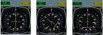
- Mach 1.1 (~ FL 330), FPM → ~2.000: somewhere above Mach 1.1 drag reduces significantly – be prepared to increase the climb rate again drastically to about ~2.000, then again reducing to ~1.000
|
|
|

- Mach 1.3 (FL~360): Air-Intakes open automatically, providing more thrust. Be prepared to increase FPM ~2.500 again
- Mach 1.7 (~FL470): AB OFF again (Stop afterburner (ctrl+F))
- ensure 513 is preset in (62) and AA is active !!
- FL513: System will automatically switch from AA to AH
- MACH 2.02: MH on (Mach Hold) + both AT on (Auto-Throttle)
- continue Fuel-Pumping until M/CG is centered, otherwise you fly with much drag which will increase your fuel consumption
- check Target Airport, Weather, Runways, etc.
Supersonic descent
The descent from FL513 and Mach 2.02 will take about 30 Min and/or 250-270 miles:
- Between 270-250 miles to target: MH off + Throttle off, decelerate to 350 kt/h at FL513
- WARNING: make sure you move the throttle once completely forward and then to idle – otherwise it may stay engaged in the previous condition!
- AT might start blinking because the throttle is idle!
- watch M/CG: you may need fuel FORWard very soon! During the whole descent you may need to switch FORW on/off several times!
- at 350 kt/h --> VS on (AH off), start descent with FPM 2.000 (20)
- preset AA to FL410, then prime AA (Altitude Acquire)
- at FL410 hold Altitude and decelerate to Mach 0.95 with min. throttle
- at Mach 0.95 continue descending with 2000 FPM (VS on enforces AA off automatically)
- preset AA = 10.000, predefining your minimum altitude prior to approach. You may vary the FPM according to your needs
- below 18.000 ft set QFE in (25) (field elevation pressure), check ATIS (or ask ATC or check weather of the airport in MPmap). Be aware that this QFE might be very different to the one set at the beginning of the flight! And it should be correct, if you plan to land with Autopilot (support)!
Approach
- ~40 miles from threshold: prepare the approach to the expected Runway – or define a STAR-approach – or ...
- for a normal "straight in approach":
- Set VOR into NAV2 (64) & ILS into NAV1 (55), also set the radials according to the expected runway into (58), (59), (60), (61).
- Switch (56) to INS (Inertial Navigation System)
- Align your flightpath with runway: if e.g. you want to land on runway 25, but the direct INS-radial (yellow pointer) actually points to 25.8°, then you should start correcting the INS-radial to 25°:

- set True Heading (58) to e.g. 28.5° and activate TH.
- Watch it: The TH marker (now on “N”) does not follow because the instrument shows INS values! The actual TH values you would see only when you switch the INS-display to VOR with switch (56) – which we do not do, because we want to watch the INS-pointer!)
- While the TH of the plane moves slowly to the preset TH=28.5° (i.e. to the right), the INS-pointer moves slowly towards 25° (to the left). And the vertical deviation bar starts showing that the actual heading of the plane does not match the direct path to the INS-target.
- Continue with that TH heading until the INS-pointer points directly onto 25°, then IN on (forces TH off). The plane will turn and approach the target on that radial. The deviation bar will center
- (Of course you also could use a VOR if there is one midfield of the airport and if it reaches that far – the nice thing about INS is: It always is available (even 20.000 miles away and always is located in the center of the target.)
| 325 kt/h (M 0.8) |
| 270 kt/h AND below 20.000 ft |
| 270 kt/h (M 0.7) |
- Below 10.000 ft → 250 kt/h maximum speed
- Main Landing Light on (over windshield at left)
- Nose down 5°
- contact ATC and follow advise, or:
- ~25 miles from threshold: descent to 2.000 ft and hold 220 kt/h
- Approach Radial: Make sure you are close to the radial of the active runway, either by above INS-settings or by standard VOR-procedures
- VL on (VOR1 Lock): Check (11) (The indications in (18) and (17) are not usable because they still show INS – not VOR!): Only after the yellow needle shows the ILS-localizer active switch VL on (forcing IN off).
- RAD/INS → RAD (56): That will display the VOR1 in (18) and (17) (of course also (4) must be switched to DEV1! Remember: Only DEV1 can be used for Radial flying!). There should be needed only minor corrections to center the localizer, and those are done now by the Autopilot!
- GL on (Glideslope): Watch (9) and/or (21) for a stable confirmation that the DME reading is stable and wait till the Glideslope indicator (in (17) and/or (18)) is centered, only then activate GL. 'Otherwise the plane might perform a very drastic climb or descent in order to acquire the Glideslope altitude!'
- ~10 mi from threshold: keep 200 kt/h (You may still have a gross-weight far above the maximum landing weight – so keep speed a little higher than usual!)
- Follow the ILS beam
Landing
- Watch "Altitude to Ground" in (23)
- Landing Gear (G) at about "Outer Marker" (32) blue
- Nose 12.5 degrees (full down)
- 750 ft AGL: switch AP off (Autopilot with Ctrl+D) and AT off (Auto-throttle)
- hold pitch at 10° - adjust descent-rate with speed/throttle
- VREF 162 kt/h for touchdown (rather stay a little faster!)
Taxiing
- Nose up to 5°
- Switch Off engines 2 + 3
- get clearance to taxi
Parking
- Switch off engines
- Nose and visor up, as weather seal.
Advanced Topics
Pre-flight fuel planning
Since the Concorde is trimmed by fuel pumping, one cannot simply fill a few tanks from the standard Flightgear menu and fly away. The Concorde menu (Ctrl+I) offers under 'Fuel' a few options, some of which are useful for flights of the full range ('max takeoff') or short subsonic test flights ('max landing'). However, if one flies an intermediate distance with the max. takeoff fuel load (as in the above tutorial), the Concorde is above its maximal landing weight on arrival. Thus, it can necessary to adjust the fuel load manually for such flights via the Flightgear menu.
The first problem in doing so is that the tank number in the Flightgear menu is not the same as in the Concorde internal scheme. The following table provides the mapping, in the following, tanks are always referenced by the Concorde scheme.
| Flightgear menu | Concorde scheme | trim |
|---|---|---|
| 0 | 1 | F |
| 1 | 2 | A |
| 2 | 3 | A |
| 3 | 4 | F |
| 4 | 5 | F |
| 5 | 6 | A |
| 6 | 7 | A |
| 7 | 8 | F |
| 8 | 9 | F |
| 9 | 10 | F |
| 10 | 11 | A |
| 11 | 5A | A |
| 12 | 7A | A |
The table also shows the trim effect of the tank as 'F' (forward) or 'A' (aft), e.g. if tank 11 is filled, it shifts weight to the rear (which should be also clear from tank location schematics above). For ease of handling, first fill the four collector tanks (1-4) equally. Their trim effect roughly cancels apart from a small weight shift aft. If you need more fuel, fill the transfer tanks (5-8) equally. Again, their trim effect tends to cancel, leaving only a small weight shift aft. For still more fuel load, fill the auxiliary tanks next (5A and 7A), again this results in a weight shift aft.
Whatever the fuel load of the tanks so far, it is always possible to trim the Concorde properly by using the trim tanks, which when completely filled give a strong weight shift forward (this is the reason tank 11 is not completely filled when 'max. takeoff weight' is chosen). So, after selecting the desired fuel load of collector, transfer and auxiliary tanks, trim properly for takeoff using the trim tanks (9-11).
When taking off without full fuel load, it is actually best to have the smallest amount of fuel needed to center M/CG in the trim tanks. This makes fuel management in flight much easier - basically one can treat the fuel system as two separate systems - the fuel in the trim tanks is only used to balance the aircraft by pumping it back and forth, whereas the rest of the tanks feed the engines. As a result, trimming is achieved very quickly.
Engine Startup
Since the Concorde model is initialized with all four engines running, knowing the engine startup procedures is not absolutely necessary. Note that there is also a simplified engine startup/shutdown available on the 2-d panel. The full engine startup procedure utilizes the engineering panel (Ctrl+E) quite heavily, and only the final engine start is controlled by the pilot by the four HP valves (overhead).

Important panels
In order to start, an engine needs fuel, airstream and electrical power. The relevant areas of the engineering panel (Ctrl+E) are:
The engine feed pumps

The pump controls are located at the low end of the fuel management panel. Each pump has a set of three switches (1a - 1d), if they are put to 'off', the engine will no longer receive fuel. Usually the switches should be 'on' before trying to start an engine (also check fuel level in the tanks above - the engines will not start if the plane has no fuel). In case an engine should be completely deactivated (because of damage or overheat) it is probably a good idea to shut down its fuel supply.
Air bleed control

The airbleed control panel has a series of switches (1a - 1d) for the primary airstream which should be 'open'. The pressure gauges (2a - 2d) show if there is air pressure available in the engine. If the gauge reads zero, the engine cannot be started. The cross bleed valves (3a and 3b) can be opened to start an engine utilizing the pressure of an adjacent engine, or using ground supply. In flight, they should normally be closed.
Electrical generating

Electrical power is usually generated from the engines, the relevant panel is located on the right hand side of engineering. The power gauges (1a - 1d) show the power generation. The ground power indicator (2) lights up if the Concorde is plugged into an external power source - the switch below must be in 'close' position to utilize external power and in 'trip' before taxiing. The four generator switches (3a - 3d) activate power generation from a running engine. They should probably be 'off' before starting an engine and only 'on' as soon as the engine is running.
Engine starting

The four engine starter switches (1) are hidden on the lower left side of the engineering panel. They should be switched to 'start' to start an engine on the ground and to 'relight' to restart an engine in the air (that requires the 3rd mouse button). Below is the busbar switch (2) and the RAM air turbine (3) which are needed for emergency engine restart in the air.
Cold engine startup on the ground
Since the plane is initialized with running engines, in order to get into the situation of a cold start you have to switch them off. From the pilot's seat, close all four HP valves (overhead). A bunch of warnings informs you that the engines, electricity and other systems are down - deactivate the warning lights.
- External power: Bring up the concorde menu (Ctrl+I), check that under 'Ground' 'Air bleed' and 'Electrical power' are activated. Next bring up the Steward view (Ctrl+W) and switch 'Ground supply' to 'on'.
- Generators: Go to engineering (Ctrl+E), switch the four generator switches to 'off', switch ground power to 'close' - all panel gauges should come to life, indicating that there is power available.
- Air bleed: On the Air bleed control panel, open one of the cross bleed valves. The corresponding pressure gauge should show some pressure (generated by the ground crew).
- Engine starter: On the engine starting panel, put the switch for the selected engine to 'start'.
- HP valve: Back in the cockpit, open the HP valve for the selected engine. The engine should now start.
- Power generator: Back in engineering, start the power generator assoicated with the running engine. The power gauge should now show that power is generated. You can switch the ground power to 'trip'. You can also close the cross bleed valve of the running engine. Do not switch 'Ground supply' in the steward view off yet - air bleed from the ground is still needed.
- Opposite engine: Now repeat the procedure from air bleed on for the opposite engine, i.e. after starting engine 1 start 4, or after starting 2 start 3. With two engines ready, the Concorde is now prepared for taxiing - disconnect ground power from steward view (Ctrl+W) and taxi to the runway.
Remaining engine startup on the ground
Following usual procedure, you should reach the runway with two engines running. Then the Concorde is independent of any ground supply. In order to start the two remaining engines before takeoff, do the following:
- Air bleed: On the airbleed control, open two adjacent cross-bleed valves. The pressure gauge next to the running engine will now also show pressure.
- Engine starter: Put the switch for the selected engine to 'start'.
- HP valve: Back in the cockpit, start the engine by opening the HP valve.
- Cleanup: Switch on the electrical generator for the engine and close the cross bleed valves.
- Repeat Now repeat the procedure with the last engine.
Engine restart after flameout in the air
Should an engine go out during flight, restart is actually quite simple, as the ambient airstream through the engine is usually enough to start it, and power is produced by the remaining engines. Make sure that the HP valve is closed before re-starting the engine. To re-activate an engine in-flight, do the following:
- Power generator: Switch the power generator 'off'
- Engine starter: Switch the engine starter to 'relight'
- HP valve: Back in the cockpit, open the corresponding HP valve. The engine should come alive.
- Power generator: Switch the power generator back to 'on'
Emergency engine restart after full flameout
If all four engines fail during flight, the situation is a bit more complicated, since no electrical power is available. Nevertheless, the following procedure works:
- Copilot: Since the autopilot is off without electrical power, someone needs to fly the plane while you are busy in engineering. Call up the Concorde menu (Ctrl+I) and activate the virtual Copilot, he takes care of the cockpit.
- HP valves and power: Close all HP valves, switch the power generators off.
- RAM air turbine Switch both switches of the RAM air turbine on. This is a power generator which utilizes the airstream around the plane. Some electricity should come back.
- Busbar switch With the busbar switch above, select an engine to start.
- HP valve: Back in the cockpit, open the corresponding HP valve. The engine should come alive.
- Power generator: Switch the power generator back to 'on', swith the busbar to 'off'
- Remaining engines Now that power is back on, start the remaining engines with 'relight' as described above
When this is done, switch autopilot back on, kindly thank your copilot and ask the stewardess for a cup of coffee - you earned that...
Fuel Management
The simplified trimming procedure using the 2-d panel options is described above. The realistic handling of trimming and fuel flow is done from engineering (Ctrl+E) using the Fuel Management panel. The main elements of this panel are the various valves connecting the different tanks, the switches for pumps pressurizing the tanks and the gauges for fuel content, fuel consumption and M/CG. The basic operating principle is simple - open a valve and fuel may flow between tanks, activating a pump will make fuel flow if the valve is open and more active pumps cause faster fuel flow. The trick is of course knowing which valves and pumps to activate in what situation. The system has a lot of redundancy, so that the flight engineer can compensate for failing pumps or valves. For example, tanks have at least two fuel pumps.
Description of the Fuel Management Panel
The upper part of the Fuel Management Panel

- Inlet valve switches - these control the connection between tanks 9 and 11 and need to be opened for balancing into forward or aft direction. Nearby are override switches.
- Fuel gauge of tank 9.
- Pump switches for tank 9.
- Standby inlet valves which allow to pump fuel from tank 9 to almost any other tank. From left to right, the valve switches open connections to tanks 5,6,1,2,3,4,10,7 and 8. Tank 11 can be filled via the switches 1a and 1b, and only the auxiliary tanks 5A and 7A cannot be connected directly from tank 9.
- Pump switches for tank 5A.
- Pump switches for tank 7A.
- Pump switches for tank 10.
- Fuel gauge of tank 5A.
- Fuel gauge of tank 10.
- Fuel gauge of tank 7A.
- Jettison buttons.
The lower part of the Fuel Management Panel

- Trasfer valve switch for the connection between tanks 5 and 5A.
- Trasfer valve switch for the connection between tanks 7 and 7A.
- M/CG gauge (same instrument as in the cockpit).
- Trim transfer auto master switch
- Pump switches for tank 5.
- Fuel gauge of tank 5.
- Inlet valve switch
- ???
- Inlet valve switch
- Pump switches for tank 7.
- Fuel gauge of tank 7.
- Total fuel gauges
- Pump switches for tank 6.
- Fuel gauge of tank 6.
- Interconnecting valve switch between tank 6 and 7.
- Interconnecting valve switch between tank 5 and 8.
- Pump switches for tank 8.
- Fuel gauge of tank 8.
- Fuel gauge of tank 1.
- Fuel gauge of tank 2.
- Fuel gauge of tank 3.
- Fuel gauge of tank 4.
- Pump switch for system green and override.
- Pump switch for system blue and override.
- Engine feed pumps for engine 1.
- Engine feed pumps for engine 2.
- Engine feed pumps for engine 3.
- Engine feed pumps for engine 4.
- Fuel gauge of tank 11.
- Crossfeed valve switches between engines 1 and 2.
- Crossfeed valve switches between engines 3 and 4.
- Pump switches for tank 11.
- Pump switches for tank 11.
- Fuel consumption gauges for engines 1-4.
Trimming procedures
In order to trim the Concorde properly, typically three different procedures are needed: 1) Fuel transfer from tanks 9 and 10 into tank 11 (this corresponds to the Aft option in the simplified fuel management of the 2-d panel) 2) fuel transfer from tanks 9 and 10 to the engines if tank 11 is already filled to continue trimming (this is only needed if the fuel load is close to maximum takeoff weight) and 3) fuel transfer from tank 11 into tanks 9 and 10 (this corresponds to the Forw option in the simplified scheme.
In order to shift fuel from front to rear tanks, do the following:
- Inlet valves Open the inlet valves (1a and 1b) to connect tank 9 and 11.
- Fuel pumps Switch the fuel pumps of tank 9 (3a and 3b) on, and fuel flow should start.
- Further trim If more trim is needed, also open the standby inlet valve (4b, 3rd switch) connecting tank 9 and 10, activate the fuel pumps of tank 10 (7a and 7b). This transfers fuel from tank 10 into tank 9, where it is pumped on to tank 11 as long as the pumps of tank 9 are running and the inlet valves are open.
- End trimming Close the inlet valves, the standby inlet valve and switch off the pumps.
In order to transfer fuel from the forward trim tanks to the engines, follow this procedure:
- Standby inlet valves Open the standby inlet valves (4a and 4b) connecting tank 9 with tanks 1,2,3 and 4.
- Fuel pumps Switch the fuel pumps of tank 9 (3a and 3b) on, and fuel flow should start.
- Further trim If more trim is needed, also open the standby inlet valve (4b, 3rd switch) connecting tank 9 and 10, activate the fuel pumps of tank 10 (7a and 7b). This transfers fuel from tank 10 into tank 9, where it is pumped on to tanks 1,2,3 and 4 as long as the pumps of tank 9 are running and the valves are open.
- End trimming Close the standby inlet valves and switch off the pumps.
On descent when forward trim is again needed, the following is required:
- Inlet valves Open the inlet valves (1a and 1b) to connect tank 9 and 11.
- Fuel pumps Switch the fuel pumps of tank 11 (44a and 44b) on, and fuel flow should start.
- End trimming Close the inlet valves, the standby inlet valve and switch off the pumps.
Managing normal fuel flow
Managing the normal flow of fuel to the engines is not particularly involved. The engines are connected to tanks 1-4 via the engine feeding pumps (36, 37, 38 and 39), so all fuel must eventually pass through these tanks. If there is a problem with one of these tanks or fuel pumps, the crossfeed switches (41a, 41b and 42a, 42b) can be activated to feed both engines 1+2 or 3+4 from a single tank. The fuel consumption gauges (45a, 45b) show the actual fuel flow to the engines.
Tanks 1-4 should normally be fed from tanks 5-8 (except when there is need to empty a trim tank). It seems to be sufficient to activate the fuel pumps (16, 21, 24 and 28) to empty the set of transfer tanks into the collector tanks. If needed, there are also interconnection valves between tanks 6 and 7 (26) and 5 and 8 (27). If they are used, this corresponds to the Cross balancing option in the simplified scheme.
Finally, the auxiliary tanks 5A and 7A can be connected to the transfer tanks 5 and 7 via the transfer valves (12 and 13) - if the fuel pumps on 5A and 7A (5 and 6) are switched on, the tanks empty into 5 and 7. This corresponds to the Aux option in the simplified scheme.
Appendix
General Climb Performance
Just for those who wonder why the "Climb" is that complex: See here the theoretical calculations for the Concord, and merged into it the data resulting from my flight-tests. See also my data-recordings in the next chapter.

- red : The theoretical max/min speed-envelope
- green: The “Maximum Operating Speed” limits
- blue/white: the theoretical Mach values according to speed and altitude
- gray + FPM values: The “Recorded Flight Data” of one of my trips, see the data in the following table
See especially the very much changing relationships between CAS, Mach, Gnd-Speed with altitude.
Recorded Flight Data EHAM --> LIRF
| Time | FL | FPM | T/CG | TAS | MaxMach | Mach | CAS | Miles | Fuel | remark |
|---|---|---|---|---|---|---|---|---|---|---|
| Start | ||||||||||
| 00:00:00 | 0 | 0 >> 2000 | --- | --- | --- | --- | --- | 700 | 93,000 | AB on |
| 00:02:15 | 20 | 2000 >> 4000 | 0.9 | 260 | 0,55 | --- | 250 | 702 | 91,400 | AB off |
| 00:04:53 | 100 | <3500> | 0.9 | 294 | 0,7 | 0.46 | 250 | 697 | 90,156 | AB on |
| 00:06:00 | 140 | <3000> | 0.9 | 388 | 0,77 | 0.61 | 316 | 689 | 88,824 | AFT Pumps on |
| 00:06:54 | 170 | 3000 >> 750 | 0.9 | 494 | 0.8 | 0.8 | 391 | 683 | 88,085 | AB off |
| 00:09:55 | 240 | 4000 >> 400 | 1 | 569 | 0.95 | 0.95 | 406 | 656 | 86,291 | AB on |
| 00:13:10 | 330 | 2000 >> 1000 | 1.12 | 637 | 1.12 | 1.12 | 405 | 624 | 83,617 | WATCH: Steep Speed Increase |
| 00:16:00 | 360 | 2500 >> 2000 | 1.25 | 746 | 1.33 | 1.33 | 451 | 592 | 81,505 | WATCH: again increase to FPM 2500ppp |
| 00:19:25 | 440 | 2000 | 1.4 | 992 | 1.7 | 1.7 | 525 | 543 | 78,451 | AB off |
| 00:23:45 | 513 | 0 | 1.49 | 1160 | 2.02 | 2.02 | 524 | 464 | 75,925 | |
| descent | ||||||||||
| 00:00:00 | 513 | 0 | 1.2 | 1160 | 2.02 | 202 | 524 | 270 | 70,056 | |
| 00:04:23 | 513 | 2000 | 1.2 | 783 | --- | 1.37 | 350 | 200 | 69367 | |
| 00:09:51 | 410 | 0 | 2.15-1.1 | 542 | --- | 0.95 | 266 | 138 | 68650 | |
| 00:25:19 | 100 | 2000 | 0.7-1.12 | 245 | --- | --- | 250 | 32 | 67700 | |
| landed | ||||||||||
| 00:37:47 | 65257 | Landed –-> at terminal |
Concorde unique Keys
| Key | Function |
|---|---|
| [ ] | raise/lower nose |
| left/right | autopilot heading |
| floating view left/right | |
| up/down | increase/decrease autopilot altitude |
| floating view front/aft | |
| home/end | increase/decrease autopilot altitude (slow) |
| floating view front/aft (fast) | |
| page up/down | increase/decrease autothrottle speed |
| floating view up/down | |
| a/A | speed-up |
| alt-b | emergency brakes |
| f | full cockpit |
| alt-g | gear standby |
| alt-n | nose standby |
| q | quit speed-up |
| S | swaps 2D panel |
| y | toggle yoke |
| ctrl-A | altitude acquire |
| ctrl-D | disconnect autopilot |
| ctrl-E | engineer view |
| ctrl-F | reheat (afterburner) |
| ctrl-G | glide slope |
| ctrl-H | heading hold |
| ctrl-I | menu |
| ctrl-J | copilot view |
| ctrl-K | observer (floating) view |
| ctrl-N | nav 1 hold |
| ctrl-O | overhead view |
| ctrl-P | pitch hold |
| ctrl-R | radio frequencies |
| shift-ctrl-R | crew text |
| ctrl-S | speed acquire |
| ctrl-T | altitude hold |
| ctrl-W | steward (floating) view |
| shift-ctrl-X | restore floating view |
| ctrl-Z | virtual crew |
