Space Shuttle
 Space Shuttle Atlantis in orbit | |
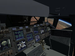
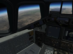
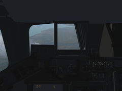
 Space Shuttle cockpit (April 2015) | |
| Type | Spacecraft |
|---|---|
| Author(s) | Thorsten Renk, Richard Harrison |
| FDM | /JSBSim, /JSBSim, /JSBSim, /JSBSim, /JSBSim, /JSBSim, /JSBSim, /JSBSim |
| --aircraft= |
/SpaceShuttle SpaceShuttle-orbit SpaceShuttle-launch SpaceShuttle-entry SpaceShuttle-approach SpaceShuttle-TAEM /SpaceShuttle SpaceShuttle-orbit SpaceShuttle-launch SpaceShuttle-entry SpaceShuttle-approach SpaceShuttle-TAEM /SpaceShuttle SpaceShuttle-orbit SpaceShuttle-launch SpaceShuttle-entry SpaceShuttle-approach SpaceShuttle-TAEM /SpaceShuttle SpaceShuttle-orbit SpaceShuttle-launch SpaceShuttle-entry SpaceShuttle-approach SpaceShuttle-TAEM /SpaceShuttle SpaceShuttle-orbit SpaceShuttle-launch SpaceShuttle-entry SpaceShuttle-approach SpaceShuttle-TAEM /SpaceShuttle SpaceShuttle-orbit SpaceShuttle-launch SpaceShuttle-entry SpaceShuttle-approach SpaceShuttle-TAEM /SpaceShuttle SpaceShuttle-orbit SpaceShuttle-launch SpaceShuttle-entry SpaceShuttle-approach SpaceShuttle-TAEM /SpaceShuttle SpaceShuttle-orbit SpaceShuttle-launch SpaceShuttle-entry SpaceShuttle-approach SpaceShuttle-TAEM /SpaceShuttle SpaceShuttle-orbit SpaceShuttle-launch SpaceShuttle-entry SpaceShuttle-approach SpaceShuttle-TAEM /SpaceShuttle SpaceShuttle-orbit SpaceShuttle-launch SpaceShuttle-entry SpaceShuttle-approach SpaceShuttle-TAEM /SpaceShuttle SpaceShuttle-orbit SpaceShuttle-launch SpaceShuttle-entry SpaceShuttle-approach SpaceShuttle-TAEM |
| Status | Beta |
| FDM |
|
| Systems |
|
| Cockpit |
|
| Model |
|
| Development | |
| Repository |
|
| Download |
|

| Space flight |
|---|
| in FlightGear |
| Space Shuttle |
| Vostok-1 |
The NASA Space Shuttle was the world's first operational space plane capable of reaching orbit. It was operated from 1981 to 2011 on a total of 135 missions during which two orbiters, Challenger and Columbia, were lost in accidents.
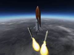
The Shuttle launch system components include the Orbiter Vehicle (OV), a pair of solid rocket boosters (SRBs) and the external tank (ET) containing the liquid hydrogen and oxygen fuel for the engines of the orbiter. Out of these, only the external tank is expendable, the SRBs splash into the sea shortly after launch and are recovered, and the orbiter itself returns to a landing site where it lands like an airplane.
The mixture of a rocket-like launch, a spacecraft-like near ballistic early atmospheric phase and an airplane like approach and landing makes the Space Shuttle a truly unique flying experience.
Project Aim
The aim of the Shuttle Project is to create a highly realistic simulation of the capabilities of the Space Shuttle in FlightGear. While most of the time the real Shuttle is under the control of automatic guidance systems, there are fallback modes to control the spacecraft manually, the so-called CSS (control stick steering) modes, and it is these modes we primarily try to implement.
In addition to the real avionics and control modes, the idea is also to provide various 'educational' modes and instruments such as to explore and appreciate certain aspects of a Shuttle mission more.
The NASA technical reports server supplies a large base of wind tunnel and in-situ performance data of both the mated launch vehicle and the orbiter, and the aerodynamics of the simulated shuttle is based on these documents. The authoritative source for procedures for trajectory management, instrumentation, limits and emergency procedures is the Space Shuttle Crew Operations Manual and currently a normal mission, i.e. ascent, orbital insertion, de-orbit, entry, terminal area energy management and landing can be flown largely 'by the book', i.e. following the real procedure for CSS. As of May 2015, this does not yet hold for emergency procedures.
Limit and failure modeling
The project contains code to simulate the various structural and aerodynamical limits as well as component failures based on sections 4 and 6 of the Space Shuttle crew manual.
The general philosophy on limit modeling is that they can be treated dependent on a user setting as 'soft', 'hard' and 'realistic'. Where applicable, warnings when the state of the orbiter is getting dangerously close to a limit are called out in addition to a recommendation how to deal with the situation. Dependent on the trajectory of the orbiter, there may or may not be sufficient time to redeem the situation.
- soft
- Limit violations are called out, but their violation has no consequences for aerodynamics or component failures.
- hard
- Any limit violation immediately ends the simulation.
- realistic
- In reality, components do not necessarily fail immediately if used outside their design specs. This option applies a probabilistic failure model in which the chance for a component to fail grows with the degree of limit violation. The failure may or may not be immediately visible, e.g. too much qbar upon ascent may damage the heat shield, but this may not be apparent (unless specifically checked) until the heat shield fails upon atmospheric entry.
Component failure is modeled gradually where applicable - while a tire can only blow or not blow, an airfoil or a thruster for instance may lose a certain percentage of its efficiency.
The mated launch vehicle
At liftoff, thrust for the shuttle is provided by its three main engines (SSMEs) and the two SRBs. The assembled launch configuration has a height of 184.2 ft (56.1 m) and a mass of about 4,470,000 lb or 2.030 tons (in addition to payload), over 90% of this being propellant. The main engines would at this point be incapable of lifting the launch stack.
The SRBs burn an ammonium perchlorate composite fuel with a relatively low ISP of 268 s in vacuum, supplying 2,800,000 lbf of liftoff thrust each, this is supplemented by the SSME burning liquid hydrogen/oxygen with an ISP of 455 s, supplying an additional total liftoff thrust of 1,180,000 lbf. At liftoff, the shuttle hence reaches a thrust/weight ratio over 1.6, i.e. it leaves the launch pad rapidly.
Control during ascent is provided by thrust vectoring of both the SRB and SSME nozzles. The real-world CSS scheme is a 'stick controls rates' scheme which for stick to neutral does 'attitude hold' which makes it possible to control the launch trajectory very precisely.
The Solid Rocket Boosters
Each SRB weighs about 1,300,000 lb, out of which 1,100,000 is propellant weight. The propellant of the SRBs is shaped to provide a high liftoff thrust, followed by a thrust reduction during the phase of the highest dynamical pressure (max. qbar). The actual thrust as a function of time is fairly complicated:

The distribution is faithfully modeled in FG and the definitions to match the real thrust characteristics is taken from the JSBSim code repository
The SRBs can not be throttled, once ignited, they provide thrust as explained above. SRB ignition takes place some three seconds after main engine ignition, and once they ramp up to full thrust, the shuttle has no choice but to leave the launch pad. For thrust vectoring, SRB nozzles can be gimbaled up to 8 deg in both pitch and yaw axes, a roll moment is created by gimbaling the two SRBs in opposite directions.
As of May 2015, SRB separation happens automatically once the thrust drops below some threshold to avoid having to drag dead weight, but there is no provision to manually separate. The SRBs are pushed away from the remaining launch vehicle by separation motor burns. These (including the separation animation with still burning SRBs) are modeled in FG, however due to technical issues with the submodel code at high velocities, thrust of the separation motors in the sim is set larger than in reality to provide the same visual separation dynamics.
The SRBs are implemented as ballistic submodels, i.e. they follow a correct trajectory and ascent with the shuttle, however since (unlike the shuttle) they are not accelerating, they visually fall behind quite quickly.
The Main Engines
The three main engines (SSMEs) are used during ascent and burn propellant from the ET. They are mounted in a triangular configuration at the stern, tilted by 13 degrees with respect to the spacecraft main axis and can be gimbaled by 10.5 degrees in the pitch and by 8.5 degrees in the yaw axis. The reason for the tilted arrangement is to have a sensible CoG of the OV together with the ET during the later ascent stages. The heavy oxygen is stored forward in the ET, leading to a fairly forward CoG for the mated vehicle such that the SSMEs can be vectored through the CoG. This assembly is faithfully modeled in FG.
The engines can be throttled between 67 and 109% of rated power, this is necessary to keep the launch vehicle within structural limits during the high qbar phase in the atmosphere and later close to MECO as the propellant in the ET is almost depleted. Thrust increases during ascent as the exhaust gases do no longer have to push against an atmosphere. Both liftoff and vacuum thrust of the modeled engines are in agreement with published values.
Since the SSME's are mounted much closer to each other than the SRBs, the Shuttle loses significant yaw and roll maneuverability after SRB separation. However as the spacecraft is nearly out of the atmosphere by then, no such maneuverability reserves are actually needed.
In FG, the throttle controls all three SSMEs during ascent. Engines ignite once throttle is moved above 67%, this triggers the SRB ignition. If the throttle is moved below 67%, the engines will stop, however they will restart once throttle is moved again up as long as fuel is available in the ET.
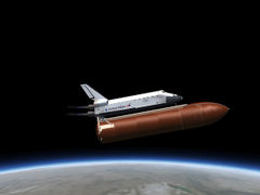
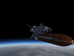
The propellant for the SSMEs is carried in the ET. The tank has a liftoff weight of approximately 1,680,000 lb (760 tons) and a dry weight of about 66,000 lb. The ET is the only expendable component of the launch stack, it is dropped after MECO upon almost reaching orbit and then the shuttle uses the OMS to attain orbit while the tank re-enters the atmosphere half an orbit later and breaks up during entry.

In FG, the tank is normally separated using d. This is vetoed if the Shuttle has unsafe yaw, pitch or roll motion in which case the RCS should be used to stabilize the orbiter before ET separation. If an emergency separation needs to be performed, Control+d overrides the veto. At separation, a translational RCS burn will automatically push the shuttle away from the tank.
After separation, the ET will approximately co-orbit with the OV, i.e. unless the Shuttle ignites the OMS engines, the tank will be visible for a long time, slowly drifting off, and it is quite possible to use the Shuttle's RCS engines to do a visual inspection of the tank.

A note on aerodynamics of the mated vehicle
With the ET and SRBs attached, the launch stack has quite different aerodynamical characteristics than the OV alone, for instance the stack is more yaw-stable than the orbiter and its pitching moment as function of alpha and rolling moment as function of beta are very different. Where such data could be obtained from wind tunnel tests with the mated stack, it has been used in the simulation.
As in reality, the simulated shuttle has an automated downward elevon deflection schedule with Mach number upon ascent to provide further load relief for the wings (with corresponding aerodynamical forces acting).
In general though, aerodynamical effects are subleading, the ascent dynamics is dominated by the thruster forces and the flight control systems have a large margin to compensate for them.
CSS DAP schemes for ascent
During ascent, the stick controls thrust vectoring for both SSMEs and SRBs. The following two DAP schemes are available:
- Thrust vectoring
- This is the real CSS ascent mode for the shuttle in which stick motion controls rate, stick to neutral commands an attitude hold. Internally a PID controller vectors the thrusters and uses the stick input as a bias for the error. This is a very stable scheme and can be easily used to achieve high precision in controlling ascent speed or orbital inclination.
- Thrust vectoring (gimbal)
- This is an educational scheme in which the stick motion directly controls the engine gimbal, i.e. the pilot needs to do the task of the PID controller himself. To make things somewhat easier, the engines are automatically vectored through the stack's CoG, i.e. outside the atmosphere stick neutral corresponds to zero moments acting on the stack. In the atmosphere, the control input hence needs to compensate for aerodynamical forces. Launch in this scheme is fairly rough and it is not possible to reach high precision, but it is possible to fly into orbit and gain a first-hand experience of the forces acting on the stack.
m switches between the ascent DAPs. Control+m switches from the ascent to the orbital DAP modes (do not use an orbital DAP for ascent control unless you know very well what you're doing).
Ascent structural and aerodynamical limits
The following structural and aerodynamical limits need to be observed during ascent:
- Dynamical pressure qbar < 819 lb/sqf (modeled)
This is a structural limit for the orbiter and mated stack, in actual operations the orbiter should be kept below 650 lb/sqf.
- Wing bending moment CBW between -0.019 and 0.019 (not modeled)
At max qbar, the wing bending moment is a function of Mach number and AoA. Since Mach number is close to 1.4 in this phase of the flight, this limit basically translates into alpha between -8 degrees and 2 degrees. This can only be achieved if the orbiter is in inverted flight.
- Translational accelerations Nx between 0 and 3.11 g (modeled), Ny between -0.18 and 0.18 g (not modeled) and Nz between -0.06 and 0.73 g (not modeled).
These are structural limits of the mated stack to acceleration rather than aerodynamical forces. Especially the Nx (acceleration along the orbiter axis, i.e. main engine thrust) is important and requires to throttle down the SSMEs towards the end of the burn time.
- Late ascent trajectory may not drop below 265.000 ft (modeled)
This is a heat load limit for the external tank insulation, if the thermal protection of the ET fails, it will explode.
The Shuttle in orbit
For maneuvering in orbit, the OV is equipped with three RCS thruster clusters and the two OMS engines. The propellant for these systems is monomethylhydrazine (MMH) oxydized with dinitrogen tetroxide, resulting in a specific impulse of 312 s. This is an hypergolic fuel combination (i.e. ignites automatically). OMS and RCS tanks have an interconnect valve, however only the RCS can be fired from the OMS propellant reserves, not vice versa (currently not modeled).
The OMS engines are located at the rear of the spacecraft in pods attached to the fuselage. Two of the RCS clusters are attached to the OMS pods, one is located at the spacecraft nose.
The Orbital Maneuvering System engines
The two OMS engines provide a thrust of 6,000 lb and, using the propellant reserves of 7,773 lb of nitrogen tetrozide and 4,718 lb of MMH can induce a total velocity change of about 1000 ft/sec if all propellant is spent. Typically half of this is used to push the OV into a proper orbit after ET separation and for the de-orbit burn, the rest is available for orbital maneuvers such as inclination adjustments.
Once in orbit, in FG throttle control is transferred to both OMS engines. They can be throttled from zero to 100% of nominal thrust and are automatically vectored by the flight controls through the CoG of the orbiter. The real shuttle has a DAP for thrust vectoring of the OMS engines as well as the option of using a single engine with partial thrust vectoring, neither option is currently modeled.

The Reaction Control System
The RCS system consists of three modules, one forward at the nose and two at the OMS pods. The forward module contains 14 primary and 2 secondary thrusters, each aft module carries 12 primary and two secondary thrusters. Propellant reserves in each module are 1,477 lb of oxidizer and 928 lb of MMH. Each primary thruster has 870 lb of thrust with an ISP of 289 s, the secondary vernier thrusters produce a mere 24 lb each with an ISP of 228 s. Due to geometric constraints, the thrusters are not aligned with the main spacecraft axes or in the same plane (for instance, there is no purely downward firing nose thruster, as its nozzle would have to fire through the heat shield).
As of May 2015, this assembly has been simplified in FG as follows: Thrusters are located at their correct position (nose and aft pods), resulting in approximately correct yaw, pitch and roll moments when fired. Each basic direction in which a thruster can fire from a module is modeled as a single effective thruster (for instance, no thruster can fire backward through the shuttle from the nose module, pod thrusters can't fire towards each other) with the combined thrust of all real thrusters at the module into that direction, resulting in a total of 13 individually controlled RCS thrusters and RCS-generated control moments very close to the real assembly.
RCS DAP schemes
The real Space Shuttle has a multitude of (partially mission-specific) DAP schemes, each with different gains and deadbands, which control the thruster firing pattern in response to the controllers. A fair selection of these is implemented in FG. In the real Shuttle cockpit, there is both a rotational hand controller (RHC) and a translational hand controller (THC) to initiate either rotations of the shuttle or translational accelerations (e.g. for approach and docking). In FG, m corresponds to switching from THC to RHC and back, ⇧ Shift+m switches between the different DAPs and Control+m is the override switch to aerodynamical controls. The HUD will display the currently selected mode for clarity.
Due to the geometry of the thruster arrangement, there is significant mode mixing. For instance, a lateral translation firing nose and right pod thruster with the same thrust would also induce a yaw motion (since the modules do not have the same distance to the CoG) and a roll (since they are not in the CoG plane and in fact not even in the same plane). In most implemented modes, the FCS logic takes care of most of these effects by firing additional thruster to cancel the unwanted motion, however in some modes this is not easily possible and mode mixing has to be anticipated and accounted for manually. This is in fact the same as in the real Shuttle.
- RCS rotation
- This is a simple scheme in which the stick motion controls thrust, i.e. angular acceleration. Stick to neutral commands no thrust, i.e. the Shuttle will continue its current rotation.
- RCS DAP-A
- A precision 'stick controls rate' scheme in which stick to neutral commands an attitude hold. The mode has fairly strict deadbands and steep gains and hence uses comparatively much propellant to stabilize attitude.
- RCS DAP-B
- As DAP-A, but more permissive in terms of deadbands, trades less strictly stabilized attitude against reduced propellant consumption.
- RCS ROT TAIL ONLY
- A 'stick controls thrust' scheme in which the nose module is not used. This causes significant mode mixing.
- RCS ROT NOSE ONLY
- A 'stick controls thrust' scheme in which the OMS pod modules are not used. This causes significant mode mixing and has no roll control available (it would have some very limited roll control in reality).
- RCS ROT ENTRY
- A 'stick controls rates' DAP designed for entering the atmosphere which enforces a 'no sideslip' attitude in which the nose module is not used. This has very strict deadbands and aggressive gains to combat the yaw instability of the Shuttle upon entry, significant mode mixing and is very propellant-consuming. Do not use in orbit and only activate at the entry interface once the shuttle has the correct attitude!
- RCS translation
- The only implemented translational DAP in which the stick controls translational thrust along the spacecraft x, y and z axes. Stick to idle commands no thrust, but the Shuttle will of course retain its relative velocity to a fix point until counter-thrust is used. RCS translation can be used for emergency de-orbit burns if the OMS is not available.
Note: In orbit, 'attitude hold' refers to inertial attitude, not to attitude relative to Earth or the horizon. The orbiting Shuttle in an attitude hold mode thus has an apparent slow attitude drift with respect to the horizon. If a fixed attitude relative to Earth is desired, this needs to be actively managed.
For precision control, the keyboard is a more suitable input device than a joystick or a mouse since exact nulling of rates is somewhat easier with keystrokes.
Key mapping for RCS rotation DAP
| 4 | Roll left |
| 6 | Roll right |
| 2 | Pitch up |
| 8 | Pitch down |
| [ | Yaw left |
| ] | Yaw right |
| 5 | Cut thrust |
Key mapping for RCS translation DAP
| 4 | Left |
| 6 | Right |
| 2 | Down |
| 8 | Up |
| [ | Backward |
| ] | forward |
| 5 | Cut thrust |
Spacewalk
The Shuttle version as of May 2015 contains a 'proof of concept' spacewalk view designated 'EVA'. This is intended to simulate the view of an astronaut using a MMU. In the EVA view, use ⇧ Shift+E to initiate spacewalk. The stick then controls the MMU thrusters and m is used to switch between the translational and rotational modes of the MMU.
Before spacewalk is initiated, the yaw, pitch and roll rates of the Shuttle need to be nulled (since control inputs during spacewalk refer to the MMU, the Shuttle also can't be controlled from this view).
Once outside, the MMU can be used to float around the Shuttle, or to inspect co-orbiting objects. However, note that it is impossible to leave the EVA view unless the astronaut maneuvers back to the airlock. Currently it is not possible to see spacewalk from outside, nor can the view direction be adjusted - in a future implementation, spacewalk will be improved using the FG walker functionality.
Aerodynamics of the Space Shuttle Orbiter
The conditions encountered by the Space Shuttle span a wide range from a thin, rarefied atmosphere at Mach 27 to a sea level atmosphere flown at about Mach 0.6. Over this range of conditions, the handling characteristics change quite dramatically.
Somewhat simplified, one can divide the atmospheric entry in three phases - an initial near-ballistic entry phase in which airfoils are essentially useless, an aerodynamical entry phase in which the Shuttle is controlled by airfoils and aerodynamical forces are very noticeable on the trajectory, but in which the flight dynamics is completely different from that of an airplane and the final approach and landing phase during which the Shuttle is flown like an aircraft.

During these phases, control is passed from RCS jets to the airfoils - the inboard and outboard elevons at the trailing wing edges and the rudder/speedbrake at the tail stabilizer fin. The elevons can be deflected from -40 to 25 degrees, the rudder from -25 to +25 degrees. At a qbar of 10 lb/sqf roll control is taken over by the airfoils, at 40 lb/sqf pitch control is managed by airfoils and below Mach 3.5 finally yaw control is transferred, at which point the airplane-like phase of the entry starts. In addition to the primary airfoils, the Shuttle is equipped with a body flap which can be used to adjust trim.
During the first two phases, the Shuttle is flown with a high AoA (initially 40 degrees) to create a detatched bow shockwave which keeps the heat of atmospheric entry away from the fuselage. The characteristic hallmark of this attitude is that the stabilizer fin is shadowed by the wings - this renders the rudder ineffective above Mach 6 and makes the Shuttle yaw unstable against sideslip above Mach 2, i.e. any sideslip must be very accurately controlled by the FCS during entry or the Shuttle will tumble uncontrolled. This can not be done by the rudder, thus yaw jets remain crucial for controlling the Shuttle down to Mach 3.5.
Another effect is that the elevons deflected upward are in the lee of the wings, significantly reducing their effectivity as compared to downward deflections. However, in the entry regime, operating the elevons upward is more advantageous due to heating constraints.
Lift / Drag
Despite being designed for a gliding approach and landing, the Shuttle is not actually a very good glider - even close to approach, the glide ratio (i.e. L/D) reaches about 4.5, much less than most normal planes would have.

The maximum of L/D varies somewhat with Mach number, however for hypersonic flight thermal constraints force a high AoA and aerodynamical efficiency is a secondary concern. Only in the supersonic to subsonic phase is the Shuttle flown close to its optimum glide ratio.
Due to the Delta-wing design, L/D has no pronounced stall even at high AoA in any region. However, the need to have sufficient lift despite the relatively poor aerodynamics forces a high touchdown speed of about 200 kt.
Longitudinal Dynamics
In the near-ballistic entry phase, pitch is controlled by an attitude-hold mode of the RCS, however elevons are automatically trimmed by the FCS to negative (upward) deflections to take some of the load early on to conserve propellant.
The pitching moment induced by the control surface varies dramatically as function of Mach number.

As seen from the figure, at high Mach numbers the response is fairly flat (i.e. large elevon deflections are needed to control the Shuttle) and also non-linear (upward deflections cause much less pitching moment than downward deflection). In contrast, at low Mach numbers small elevon deflections already cause large moments and the response is almost linear. In all regimes, the pitching moment is normal force (i.e. AoA) dependent.
Since the elevons supply both pitching and roll control, at high hypersonic Mach numbers roll controls are close to being saturated with elevons deflected near full up. To open up better roll control, below Mach 10 the speedbrake is opened to provide a pitching moment relieving the elevons, and the Shuttle's body flap can also be trimmed upward.
Lateral stability
As mentioned above, during most of the entry phase, the Space Shuttle has no rudder action and the yawing moment as a function of sideslip angle beta is negative, indicating instability. This means that the FCS has to manage yaw stability by commanding yaw thrusters to maintain near zero beta, which is increasingly more challenging as the Shuttle penetrates deeper into the atmosphere and aerodynamical forces grow while thrust is reduced as compared to nominal vacuum values. This implies that a sizable amount of RCS propellant (about 1/3 of the capacity to be on the safe side) needs to be available before atmospheric entry.
Below approximately Mach 6, the rudder starts to contribute to yaw stability and from Mach 3.5 down to Mach 2 where the yawing moment finally becomes positive only the rudder is used. The roll behavior of the orbiter before any FCS is somewhat skittish as the roll moment as a function of roll rate is not a large damping term over most of the Mach range. The FCS of the Shuttle in FG therefore does not place yaw and roll axis directly under pilot control. The rudder is always commanded to minimize beta and no pilot input for the rudder should be needed or used unless sideslip is explicitly desired. The elevons are commanded to provide a simple roll damper to make control smoother.
The real Shuttle has in addition a NO Y JET mode to stabilize the orbiter during entry in which the elevons are used to control yaw. This leads to significantly reduced roll control since roll then needs to be driven by adverse yaw till the rudder picks up sufficient airflow. Currently this mode is not yet available in FG.
A note on thruster efficiency in the atmosphere
Thrusters used in the hypersonic rarefied airflow of the upper atmosphere do not only cause the yaw, pitch and roll moment by the thrust acting at a certain distance to the CoG, but also are subject to plume impingement on the orbiter fuselage and interactions with the air flow field.
While impingement generically degrades the effectivity, the interaction moment can somewhat counter-intuitively act both directions. In particular the yaw moment is increased by the airflow, helping to stabilize the Shuttle.
As of May 2015, none of these effects is modeled in Flightgear.
Control cross couplings
The Shuttle has significant cross couplings between the elevon deflection in pitch and roll mode and the rudder as a function of Mach number, all of which are faithfully modeled in FG. One of the main effects is that upward elevon deflection alters the airflow at the aft fuselage, creating additional suction effects which alter aerodynamical forces.
In particular, at supersonic speeds yaw stability is somewhat improved at high upward elevon deflection while the effect reverses at subsonic speeds. At the same time, roll control is significantly reduced at full elevon deflection, with the effect being more pronounced at low than at high Mach numbers.
Control surface effectiveness in general drops with increasing Mach number, however the speed at which this happens is different for elevons and rudder.
Entry and touchdown structural and aerodynamical limits
The following structural and aerodynamical limits need to be observed during entry and landing:
- Dynamical pressure qbar < 819 lb/sqf (modeled)
This is a structural limit for the orbiter and the airfoils, beyond this the actuators can no longer move the airfoils, leading to a loss of control. In actual operations the orbiter should be kept below 650 lb/sqf.
- Peak temperature < 2900 F (not modeled)
This is the approximate limit beyond which the thermal protection system fails, with subsequent structural failure of the overheated airframe and loss of the orbiter. Currently this limit is not checked since the modeling of the entry temperature is too rough.
- gear extension speed < 312 KEAS (modeled)
Structural limit of the gear against aerodynamical forces.
- vertical speed upon touchdown < 9 ft/sec (modeled)
This is the structural limit of the main gear struts, and their destruction is fully modeled in 'realistic' mode.
- airspeed upon drag chute deployment < 230 kt (modeled)
The drag chute has a safety pin which disconnects the chute if the airspeed is higher than the stability limit. This is fully modeled.
- roll speed of tires < 230 kt (not modeled)
This is the certified maximal speed at which the tires don't blow.
- derotation speed < 2 deg/s (modeled)
This is the structural limit for the nose gear strut, and nose gear breakage is fully modeled.
- AoA < 15 deg on touchdown (modeled)
Beyond this angle, the body flap and tail structure of the orbiter touch the ground before the main gear does.

Mission phases
The various phases of a Shuttle mission are generically subdivided into launch, orbit, entry, TAEM and approach. These can directly be accessed by appending the mission phase to the command line. This will automatically start the Shuttle in the correct configuration and the correct state for the mission selected. For instance, --aircraft=SpaceShuttle-TAEM --airport=KVBG will initialize a TAEM approach into Vandenberg.
Specific information on the mission phases can be found in the following articles:
Flying the Shuttle - Final Approach
Glossary of acronyms
| AoA | Angle of Attack |
| CoG | Center of Gravity |
| CSS | Control stick steering |
| DAP | Digital autopilot |
| ET | External tank |
| EVA | Extravehicular Activity (spacewalk) |
| FCS | Flight Control System |
| ISP | Specific impulse |
| MECO | Main Engine Cutoff |
| MMH | monomethylhydrazine (a propellant) |
| MMU | Manned Maneuvering Unit |
| OV | Orbiter vehicle |
| OMS | Orbital Maneuvering System |
| RCS | Reaction Control System |
| RHC | Rotational Hand Controller |
| SRB | Solid rocket booster |
| SSME | Space Shuttle main engine |
| TAEM | Terminal Area Energy Management |
| THC | Translational Hand Controller |
Latest development snapshot
The latest development version (possibly unstable) is found in a dedicated repository on SourceForge. You can download the latest snapshot from http://sourceforge.net/p/fgspaceshuttledev/code/ci/development/tarball. Stable updates are pushed to FGAddon periodically.
Gallery
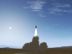
Shuttle Launch
Shuttle Launch
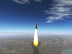
Shuttle Launch
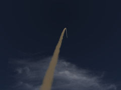
Launch smoke trail
SRB separation
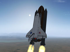
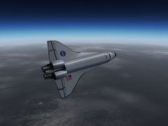
Accelerating to orbital speed
Shuttle 3d cockpit
External tank separation
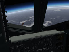
A view of Earth after reaching orbit
The ET seen from the Shuttle
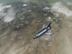
The orbiter high over Africa
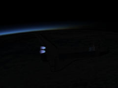
Orbital insertion burn at sunset
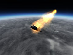
Atmospheric entry
High bank angle maneuver to control vertical speed
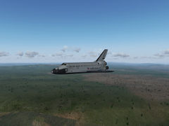
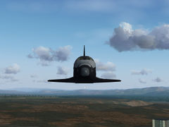
On final approach into Vandenberg
Pre-flare
Flare
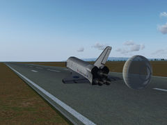
Touchdown in Vandenberg


