Howto:Add instruments to a cockpit: Difference between revisions
Openflight (talk | contribs) No edit summary |
Openflight (talk | contribs) No edit summary |
||
| Line 83: | Line 83: | ||
Change one of the values at a time; change the <y-m>-0.702</y-m> tag by 0.100 units by making it | Change one of the values at a time; change the <y-m>-0.702</y-m> tag by 0.100 units by making it | ||
<y-m>-0.602</y-m>. Several copies of the VSI can be created and the best location can be chosen. | <y-m>-0.602</y-m>. Several copies of the VSI can be created and the best location can be chosen. | ||
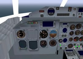
[[File:dhc8instrumentsadded.jpg|thumb|270px|Cockpit of the Dash 8.]] | |||
== Detailed Information == | == Detailed Information == | ||
Revision as of 01:31, 27 May 2012
| Work in progress This article or section will be worked on in the upcoming hours or days. See history for the latest developments. |
Many of the aircraft offerred for download on the FlightGear aircraft download page are detailled and complete. Some models, however lack instrumentation, and in many cases only basic instruments are available. Fortunately, adding new instruments is a relatively easy task. The biggest difficulty is actually placing the instrument accurately, not to get it working.
For aircraft that are licensed under the GNU GPL (all aircraft on the official downlaod page are), instruments can be re-used in other aircraft when released under the same license.
Adding instruments to existing models
Adding instruments consists of a few major steps:
- Locate an FG aircraft with a similar instrument.
- Copy XML tags relevant to the instrument files into XML file the aircraft you want to update.
- Edit the updated aircraft file to place the instrument.
An example
Let's update the instruments of the Dash 8-300Q for a start.
The existing aircraft, version v20101217 from the version 2.6 aircraft download page has the following set of basic instruments ( Radios will be covered later):
- Air Speed Indicator (ASI)
- Altimeter
- Artificial Horizon
We can see that our aircraft is lacking the following:
- Vertical Speed Indicator (VSI)
- Electronic Flight Systems Information (EFSI)
- Electronic Horizontal Situation Indicator (EHSI)
- Radio Magnetic Indicator (RMI)
- VOR instrument
First let's add the VSI (Vertical Speed Indicator) . Locate the tags for the ASI in a similar aircraft config file, the Beech 1900D (B1900D). These appear in the B1900D.xml file as follows:
<model>
       <name>VSI 1 gauge</name>
       <path>Aircraft/b1900d/Models/Instruments/vsi.xml</path>
       <offsets>
           <x-m>-4.860</x-m>
           <y-m>-0.280</y-m>
           <z-m>-0.082</z-m>
           <pitch-deg>-10</pitch-deg>
       </offsets>
   </model>
Copy this tag into the Dash8 300Q xml file containing the instruments in the models folder. The file is named dhc8-300Q.xml
The instrument now has to be placed, so to see the instrument in the aircraft panel, add it to the location of an existing instrument, this is to make sure everything is OK.
Use the x, y, z position tags of the ASI in the dhc8-300Q.xml file to place the VSI.
ASI (air speed indicator settings)
<model> <name>Pilot asi</name> <path>Aircraft/dhc8/Models/Instruments/asi300-3d.xml</path>
       <offsets>
           <x-m>-8.927</x-m>
           <y-m>-0.702</y-m>
           <z-m>2.382</z-m>
           <pitch-deg>0</pitch-deg>
       </offsets>
   </model>
Modified VSI settings:
<model>
       <name>VSI 1 gauge</name>
       <path>Aircraft/b1900d/Models/Instruments/vsi.xml</path>
       <offsets>
           <x-m>-8.927</x-m>
           <y-m>-0.702</y-m>
           <z-m>2.382</z-m>
           <pitch-deg>0</pitch-deg>
       </offsets>
   </model>
You will find that the VSI, the new instrument will appear on top of the existing one. This shows that the instrument appears in the cockpit.
FlightGear allows the creation of the same instrument copies in different locations in the cockpit. We can use this to our advantage: placing copies of the same instrument in different locations in the cockpit and selecting the right one.
An alternative is to use an existing instrument, the altimeter for example (ALT) as a reference: the y coordinate of the ALT can be used, and to place the instrument below the altimeter, use a value for "Z" as '-2.282' for example.
Change one of the values at a time; change the <y-m>-0.702</y-m> tag by 0.100 units by making it
<y-m>-0.602</y-m>. Several copies of the VSI can be created and the best location can be chosen.
Detailed Information
- X: specifies the depth, and in this case is a negative value. The increase in the value, say from -2.330 to -2.430 means the instrument will move away from you into the panel, towards the nose of the aircraft.
- Y: is the simplest, here, and simply specifies left/right values. The pilot ASI is listed with an Y value of -xxx. The value of zero means it is centre in the panel. You will notice the the co-pilot's ASI has a positive value of xxx.
- Z: gives the position of the instrument in the vertical direction. For example 2.223 will place the instrument higher than 2.123 in the panel.
The path can be left as follows, or the instrument xml files and image files can be copied to the DHC8 folder and the reference can be changed to that folder:
<path>Aircraft/b1900d/Models/Instruments/vsi.xml</path>
can be changed to
<path>Aircraft/dhc8/Models/Instruments/vsi.xml</path>
External link
- Flight instruments (Wikipedia)
