Grumman F-14 Tomcat: Difference between revisions
(Approach Power Compensator (APC) - update for current version, added section from NATOPS concerning APC usage.) |
|||
| (45 intermediate revisions by 8 users not shown) | |||
| Line 1: | Line 1: | ||
{{ | {{:{{PAGENAME}}/info}} | ||
The '''Grumman F-14 Tomcat''' is a fourth-generation, supersonic, [[:Category:Twinjets|twinjet]], two-seat, [[:Category:Variable-sweep wing aircraft|variable-sweep wing]] [[:Category:Fighter aircraft|fighter]] aircraft. The Tomcat was developed for the United States Navy's Naval Fighter Experimental (VFX) program following the collapse of the {{Wikipedia|F-111B}} project. The F-14 was the first of the American teen-series fighters, which were designed incorporating the experience of air combat against [[:Category:Mikoyan and Gurevich|MiG]] fighters during the Vietnam War. | |||
}} | |||
The '''Grumman F-14 Tomcat''' is a supersonic, | |||
The F-14 first flew in December 1970 and made its first deployment in 1974 with the U.S. Navy aboard USS Enterprise (CVN-65), replacing the [[McDonnell F-4 Phantom II|McDonnell Douglas F-4 Phantom II]]. The F-14 served as the U.S. Navy's primary maritime air superiority fighter, fleet defense interceptor and tactical reconnaissance platform. In the 1990s, it added the Low Altitude Navigation and Targeting Infrared for Night ({{Wikipedia|LANTIRN}}) pod system and began performing precision ground-attack missions. | |||
The Tomcat was retired from the U.S. Navy's active fleet on 22 September 2006, having been supplanted by the Boeing F/A-18E and F Super Hornets. As of early 2015, the F-14 is in service with only the Islamic Republic of Iran Air Force, having been exported to Iran in 1976, when the U.S. had amicable diplomatic relations with Iran. | |||
There are two variants modeled in FlightGear, both available in FGADDON. | |||
* '''F-14A''' with the {{Wikipedia|Pratt & Whitney TF30|PW-TF30-414}} engines which are susceptible to compressor stall and underpowered for the airframe) | |||
* '''F-14B''' with the {{Wikipedia|General Electric F110|GE F110-GE400}} engines improving power and reliability. | |||
== Primary Instruments == | |||
=== VDI === | |||
[[File:F-14-vdi.jpg|thumb|F-14 vdi]] | |||
The F-14 uses a Vertical Display Indicator (VDI) as the primary attitude reference instrument; there is a standby ADI just to the right. | |||
The center screen has a top part representing the sky and an artificially generated ground representation. When performing a carrier landing there will be flight director bars shown to reference the vertical deviation from the glideslope and deviation from the center line. Carrier landings require the right TACAN channel to be selected (for the carrier) and the ARA-63 to be turned on. When the primary nav is tuned to a civilian ILS frequency this will also be shown on the display although the ARA-63 specific carrier lights will not illuminate | |||
The lights on the side of the VDI that are relevant for a carrier landing are | |||
* LANDING CHK - displayed when between 6 nm and 4.5nm from from carrier and tuned correctly | |||
* ACL READY - displayed when tuned correctly and system operating | |||
* AP CPLR - displayed when system operating and within correct altitude. The AP CPLR system is not available. | |||
* WAVE OFF - displayed when landing should be aborted as outside of the parameters for a good landing. | |||
* 10 SECONDS - displayed when about 10 seconds from touchdown trap | |||
Other lights on the VDI | |||
* AP REF - Autopilot operating | |||
* REDUCE SPEED - Overspeed for flaps; or over the speed bug on the ASI | |||
* ALT LOW - below alt bug on Altimeter | |||
==== VDI Controls ==== | |||
There are controls for | |||
* HUD BRT - HUD Brightness | |||
* VDI BRT - VDI Brightness | |||
* VDI CONTR - VDI Contrast | |||
* FILTER - Changes the color of the HUD between red and green | |||
* HUD TRIM - non operational | |||
* VDI TRIM - non operational | |||
=== HUD Lights === | |||
[[File:F-14-hud-lights.jpg|thumb|HUD lights]] | |||
The HUD lights contains three sections; from left to right | |||
* AoA Indexer | |||
* Warnings | |||
* ECM/RWR status | |||
==== AoA Indexer ==== | |||
The AoA Indexer has three lights; out of which up to two can be shown at any one time. These lights are illuminated whenever the gear is down. | |||
If the indexer lights flash it indicates that the hook isn't down; unless the '''HOOK-BYPASS''' switch on the right console is selected in which case the lights will always be steady. | |||
The basic logic is that green indicates too high AoA and slow, amber is optimum and red is low AoA too fast. The light combinations are as follows: | |||
* Green V - Airspeed SLOW: AoA too high (over 16°) | |||
* Green V and Orange O - Airspeed SLIGHTLY SLOW: AoA starting to get too high (14.5° to 16°) | |||
* Orange O - OPTIMUM ON SPEED: (the doughnut) - this is the ideal AoA for an approach i.e. between 14.5° and 15.5°. Normally the aircraft is trimmed for pitch on the final approach and primarily throttles are used to control the AoA | |||
* Red upside down V and Orange O - Airspeed SLIGHTLY FAST: AoA starting to get too low (14.0° to 14.5°) | |||
* Red upside down V Airspeed FAST: AoA too low (below 14°). | |||
The airspeed guidance is secondary; it is the AoA that is important. | |||
==== Warnings ==== | |||
* WHEELS - Landing gear not locked and down - displayed when flaps are down and throttle below 80% | |||
* BRAKES - Wheel brakes are engaged; {{Key press|Shift|b}} to disengage. | |||
* NWS ENGA - Nose Wheel steering is active (below 80 knots) | |||
* AUTO THROT - APC has disengaged abnormally. | |||
=== Caution Warnings === | |||
[[File:F-14-caution-panel-all.jpg|thumb|F-14 Caution Panel]] | |||
There is a set of caution warnings that can be shown on the panel on the left console. When a light illuminates on the caution panel the '''MASTER CAUTION''' on the glareshield will also illuminate until pushed. Once pushed the caution panel warning will remain and the '''MASTER CAUTION''' light will be extinguished. | |||
Relevant warnings; | |||
* START VALVE - the engine crank selector on the engine controls panel has been set whilst the engine is running | |||
* L INLET - malfunction in the Left Inlet system | |||
* R INLET - malfunction in the Right Inlet system | |||
* OIL PRESS - oil pressure on at least one engine is below the minimum. | |||
* L RAMPS - malfunction in the left ramp system | |||
* R RAMPS - malfunction in the right ramp system | |||
* L GEN - Left generator inoperable (i.e. engine RPM below operating speed) | |||
* R GEN - Right generator inoperable (i.e. engine RPM below operating speed) | |||
* LAD / CANOPY - Ladder and/or canopy is open or not correctly latched closed | |||
* BINGO - The fuel has fallen below the Bingo bug as set on the fuel gauge | |||
* HYD PRESS - One of the hydraulic systems is below the minimum operating pressure (1800 psi). Use the hydraulic gauge to determine which system isn't functioning. Normally the Bidirectional transfer pump will keep provide pressure to the other hydraulic system from the good hydraulic system; unless the '''HYD TRANSFER'' switch on the right console is set to '''SHUTOFF''' | |||
* L FUEL PRESS - The fuel pressure in the left engine is low | |||
* R FUEL PRESS - The fuel pressure in the right engine is low | |||
* L FUEL LOW - Low fuel in the left engine tanks | |||
* R FUEL LOW - Low fuel in the right engine tanks | |||
* TRANS/RECT - The trans/rect is not operating correctly to provide DC power. This is also shown when using external power | |||
* LAUNCH BAR - Illuminated when insufficient power (< 85%) when the launchbar is engaged for a catapult launch | |||
=== Engine Gauges === | |||
[[File:F14-engine-gauges.jpg|thumb|Engine gauges]] | |||
== Right Console == | |||
[[File:F-14-right-console.jpg|thumb|F-14 Right Hand Console]] | |||
=== ARA 63 Control === | |||
Has no effect | |||
=== Air Condition === | |||
Use to control the cabin pressure and temperature. Cabin pressure will be maintained according to the correct schedule. Using Cabin press dump will de-pressurise the cabin. Air source needs to be selected to allow cabin pressure and windshield air to function. | |||
=== Ext Environment === | |||
The windshield air can be used to clear the windshield from frost and internal fogging. | |||
=== Caution Advisory === | |||
Illuminates warnings using different colours to indicate severity; cautions are orange and advisories are lighter. | |||
=== Master Light Panel === | |||
Controls the aircraft lighting | |||
=== Master Test === | |||
Only light test '''LTS''' is operational. If successful (and it always will be) the green GO will illuminate. All other tests will result in a '''NO GO''' warning | |||
=== Master Generator Panel === | |||
Used control the engine generators and the emergency hydraulically powered electrical generator. | |||
Setting the Emerg generator to off and turning both generators off will result in no electrical power to the aircraft even when both engines are running. | |||
=== Hyd Transfer Pump === | |||
Use to shutoff the emergency transfer between the two hydraulic systems. | |||
If you have the an engine shutdown the hydraulic system will be powered by this pump; if you set the pump to '''SHUTOFF''' then the hydraulic system for the shutdown engine will have no pressure. | |||
== Keyboard controls == | == Keyboard controls == | ||
=== Flight controls === | === Flight controls === | ||
{| class=" | {| class="keytable" | ||
! Key | |||
! Function | |||
|- | |||
|{{Key press|Home}} | |{{Key press|Home}} | ||
|Increase elevator trim | |Increase elevator trim | ||
| Line 29: | Line 145: | ||
|Lower flaps | |Lower flaps | ||
|- | |- | ||
|{{Key press|<nowiki>[</nowiki>}} or {{Key press|Shift| | |{{Key press|<nowiki>[</nowiki>}} or {{Key press|Shift|f}} | ||
|Raise flaps | |Raise flaps | ||
|- | |- | ||
|{{Key press|Ctrl|b}} | |{{Key press|Ctrl|b}} | ||
| Line 46: | Line 156: | ||
|{{Key press|j}} | |{{Key press|j}} | ||
|Decrease speed brakes | |Decrease speed brakes | ||
|} | |} | ||
=== Automatic flight controls === | === Automatic flight controls === | ||
{| class=" | {| class="keytable" | ||
! Key | |||
! Function | |||
|- | |- | ||
|{{Key press|Ctrl| | |{{Key press|Ctrl|a}} | ||
|Toggle | |Toggle autopilot altitude mode | ||
|- | |- | ||
|{{Key press| | |{{Key press|Ctrl|s}} | ||
| | |Toggle APC (Landing Automatic Power Control) | ||
|- | |- | ||
|{{Key press| | |{{Key press|Ctrl|h}} | ||
| | |Cycle autopilot heading mode | ||
|- | |- | ||
|{{Key press|Ctrl|t}} | |{{Key press|Ctrl|t}} | ||
|Toggle | |Toggle {{Wikipedia|Aircraft flight control systems|AFCS] (Defaut Attitude Mode) | ||
|- | |- | ||
|{{Key press|<nowiki>*</nowiki>}} | |{{Key press|<nowiki>*</nowiki>}} | ||
|Engage AFCS Altitude Mode | |Engage AFCS Altitude Mode | ||
|- | |- | ||
|{{Key press|Ctrl| | |{{Key press|Ctrl|y}} | ||
|Toggle ground spoilers armed | |Toggle ground spoilers armed | ||
|} | |} | ||
=== HSD - radar and RWR === | === HSD - radar and RWR === | ||
{| class=" | {| class="keytable" | ||
! Key | |||
! Function | |||
|- | |||
|{{Key press|h}} | |{{Key press|h}} | ||
|Cycles through HSD modes: radar - compas - ECM (RWR) | |Cycles through HSD modes: radar - compas - ECM (RWR) | ||
|- | |- | ||
|{{Key press|Shift| | |{{Key press|Shift|e}} | ||
|Decrease Radar Range | |Decrease Radar Range | ||
|- | |- | ||
|{{Key press|Shift| | |{{Key press|Shift|r}} | ||
|Increase Radar Range | |Increase Radar Range | ||
|- | |- | ||
|{{Key press|Ctrl| | |{{Key press|Ctrl|q}} | ||
|Toggles Radar Standby Mode. In standby mode the radar doesn't emit and the "STAND BY" words are displayed on the HSD screen when in TID mode. | |Toggles Radar Standby Mode. In standby mode the radar doesn't emit and the "STAND BY" words are displayed on the HSD screen when in TID mode. | ||
|} | |} | ||
=== Carrier operations === | === Carrier operations === | ||
{| class=" | See also [[Howto:Carrier]], [[Carrier over MP]] as well as a detailed [[Howto:Carrier_Landing|carrier landing howto for the F-14 Tomcat]]. | ||
|{{Key press|Shift| | {| class="keytable" | ||
! Key | |||
! Function | |||
|- | |||
|{{Key press|Shift|o}} | |||
|Lower the hook | |Lower the hook | ||
|- | |- | ||
| Line 106: | Line 212: | ||
|Raise the hook | |Raise the hook | ||
|- | |- | ||
|{{Key press|Shift| | |{{Key press|Shift|l}} | ||
|Engage launch bar ( | |Engage launch bar (keep holding until engaged) | ||
|- | |- | ||
|{{Key press|Shift| | |{{Key press|Shift|c}} | ||
|Release catapult | |Release catapult | ||
|- | |- | ||
|} | |} | ||
=== Weapons === | |||
{| class=" | {| class="keytable" | ||
! Key | |||
! Function | |||
|- | |- | ||
|{{Key press|Ctrl|w}} | |{{Key press|Ctrl|w}} | ||
|Cycle through | |Cycle through master arm switch modes (see master arm switch in cockpit). | ||
|- | |- | ||
|{{Key press|w}} | |{{Key press|w}} | ||
| Line 137: | Line 236: | ||
|{{Key press|e}} | |{{Key press|e}} | ||
|Trigger M61A1 Vulcan gun or AIM-9 missiles (depending on stick weapon mode selection) | |Trigger M61A1 Vulcan gun or AIM-9 missiles (depending on stick weapon mode selection) | ||
|- | |||
|} | |||
=== Flaps === | |||
[[File:F-14-wing-devices.jpg|thumb|F-14 Wing Devices]] | |||
The F-14 has three different types of lift augmentation on the wings. Flaps, Auxiliary Flaps and Slats. | |||
Maneuvering flaps and slats are automatically activated by the CADC to improve performance at high AoA and lower speeds. The maneuvering flaps are disabled when wings are swept outside of the permissible region for flap or slat deployment. | |||
In the picture the slats are at the front, the spoilers on the top, and the flaps at the back. The auxiliary flaps are next to the fuselage and the main flaps are behind and below the spoilers. | |||
=== Wing Sweep === | |||
[[File:F14-glareshield.jpg|thumb|F14-glareshield]] | |||
Full aerodynamic affects of wing sweep are modelled. The Wing Sweep can be controlled via the keyboard or by using the Sweep gauge in the cockpit. Use the mousewheel over the sweep angle indication to adjust the required angle of sweep. The legends to the right of the wing sweep gauge can be clicked to any of the possible modes. | |||
The CADC will provide automatic wing sweep based on Mach number. The wings cannot be swept further forwards than the CADC automatic value (to protect the airframe). | |||
The main flaps operate until the wings are swept to 55 degrees; the auxiliary flaps are only available with the wings swept to 22 degrees. Interlocks operate to prevent flap deployment with unsuitable wing sweep. | |||
It is possible to land with fully swept wings; however this should only be used in emergency situations as the landing speed is significantly increased. | |||
{| | |||
|{{Key press|<}} | |||
|Sweep Wings Forwards | |||
|- | |||
|{{Key press|>}} | |||
|Sweep Wings Aft | |||
|- | |||
|{{Key press|{{=}}}} | |||
|Wing Sweep to Automatic | |||
|- | |- | ||
|} | |} | ||
=== Miscellaneous === | === Miscellaneous === | ||
{| | {| | ||
|{{Key press|c}} | |{{Key press|c}} | ||
|Toggle canopy and access ladder | |Toggle canopy and access ladder | ||
|- | |- | ||
|{{Key press|u}} | |{{Key press|u}} | ||
|Toggle refuelling probe, three states | |Toggle refuelling probe, three states | ||
|- | |- | ||
|{{Key press|Ctrl|o}} | |{{Key press|Ctrl|o}} | ||
| Line 155: | Line 286: | ||
|- | |- | ||
|} | |} | ||
== Gallery == | |||
<gallery mode="packed"> | |||
F-14-multiple-cat-launch.jpg|F-14 USS Carl Vinson Multiple Cat Launch | |||
F-14-final-approach-ksfo.jpg|F-14 final approach KSFO | |||
F-14-formation-takeoff-lsgs-sion.jpg|F-14 Formation Takeoff (LSGS) Sion | |||
F14-top-full-burners.jpg|F14 high speed pass | |||
F-14-wings-fully-swept.jpg|F-14 with wings fully swept | |||
F14 Nimitz locked in catapult.jpg|Locked in catapult, flaps set, full afterburner, ready for take-off. | |||
F14 Nimitz going down with elevator.jpg|Going below deck on the elevator. | |||
F-14_cockpit.jpg|The pilot's "office". | |||
SunsetF-14.png|A nice dusk scene with the F-14. | |||
F14 air-to-air refuelling tanker almost reached.jpg|[[Howto:Aerial refueling|Air-to-air refueling]] with the F-14B. | |||
</gallery> | |||
== Aircraft help == | == Aircraft help == | ||
=== Engine Start === | === Engine Start === | ||
The engine | The engines can be quickstarted from the Tomcat Controls menu. | ||
[[File:F14-engine-controls-panel.jpg|thumb|Engine Controls Panel]] | |||
To perform a manual engine start, follow the instructions below. It is usual to start the right engine first to ensure that the flight hydraulics system is pressurized first. | |||
Engine start procedure: | |||
* Ensure that external air is connected (Tomcat Controls menu, Ground Services dialog) | |||
* Ensure that the fuel shut off valves are pulled out for the engine to be started. (Upper left and right of the glareshield) | |||
* On the Engine Controls panel (left console next to the throttles) select Engine Crank (L or R) | |||
* As the engine spools up the hydraulically powered emergency electrical generator will provide backup power | |||
* When the engine reaches 18% RPM push in the appropriate fuel shutoff valve. | |||
* Monitor EGT and if the value goes above 1200 Degrees C shutdown the engine using the fuel shutoff valve (this will never happen with the current engines model) | |||
* Repeat the process for the left engine. | |||
[[File:F14-engine-gauges.jpg|thumb|F14-engine-gauges]] | |||
=== Engine Shutdown === | |||
[[File:F14-glareshield.jpg|thumb|F14-glareshield]] | |||
Ensure that the wings are correctly swept, flaps raised and parking brake engaged. | |||
Pull both of the fuel shutoff valves on the glareshield. These are the yellow and black striped items on the glareshield picture. | |||
Once the fuel shutoff valve is pulled the appropriate engine will spool down and stop. When both engines are stopped there will be no hydraulic and electrical power and the cockpit will become dark. | |||
=== On Shore Takeoff === | === On Shore Takeoff === | ||
* | * Ensure wingsweep is set to automatic and wings are not overswept. | ||
* Check air brake in. | * Check air brake in. | ||
* Fuel | * Use the Tomcat Controls menu, Fuel and Payload dialog to set the required fuel load and payload | ||
* Select up to 25 degrees of flaps depending on the aircraft weight. | |||
* Release parking brakes ({{Key press|Shift-B}}) | |||
* Select MIL thrust; or afterburners if conditions dictate. It is usual operating procedure on an F-14B to not use afterburners on take off unless heavily loaded as in the event of engine failure after rotation the resulting yaw moment is likely to result in an uncontrolled departure. | |||
* At around 145 knots pull back on the stick until the nose raises at which point maintain stick pressure and when 250 feet AGL raise the gear. By 200 knots the flaps should be fully retracted. Note that as the flaps are retracted the longitudinal balance of the aircraft changes and it will tend to pitch down slightly which should be corrected by using the pitch trim. | |||
=== Hydraulics System === | |||
The F-14 has two separate hydraulic systems; identified as the '''Flight System''' and the '''Combined System'''. The flight system powers the primary flight controls and surfaces, and the combined powers everything else. | |||
Both hydraulic systems are powered by engine driven pumps. There are two backup systems for the hydraulics in case of an engine (primary) pump malfunction. The first of these is a Bi-Directional transfer pump that can powere one system from the other system. The second method is an electrically powered pump. The electrically powered pump has its own small reservoir - so once powered on the electrically powered pump should not be powered off as the hydraulic fuel expands and is lost - so there may not be enough fluid remaining in the reservoir to allow the pump to start. | |||
When there is insufficient hydraulic power the powered items will no longer function; so in the event of a dual engine flameout the flight controls will be inoperable. | |||
Sufficient hydraulic pressure for smooth flight control inputs should be available with one engine windmilling at 18% rpm or two engines at windmilling at 11% rpm. | |||
References: F14-AAD-1 p2-68 to p2-76 | |||
=== Electrical System === | |||
The F-14 electrical system is modeled sufficiently well to provide all visible effects. | |||
There is a generator on each engine powered by a Constant Speed Drive (CSD) with emergency hydraulic generator that is powered by the combined hydraulic system. | |||
* Main generators drop off at 55% N2. | |||
* Emergency generator drop off at 11-12% RPM. | |||
* Engine ignition not available below 10% | |||
* Emergency generator 1kva or kVa essential AC and Buses No1 and No2. and AFCS | |||
* When hydraulic transfer pump operating and sufficient pressure emergency power will drop to 1kVa mode and power only the essential AC and Dc No. 1 buses. | |||
In the model on the left main bus and the DC essential bus are used; however upon loss of electrical power from the main bus the non-essential will no longer be powered (e.g. the HUD, VSD, HSD). | |||
References: F14-AAD-1 p2-68 to p2-76 | |||
=== Autopilot Operation === | === Autopilot Operation === | ||
| Line 173: | Line 372: | ||
==== Autopilot Altitude Mode ==== | ==== Autopilot Altitude Mode ==== | ||
* Once in the Attitude Mode, you can select '''Altitude Mode''' by hitting {{Key press|Ctrl|a}}, then the '''AP REF''' indicator, (left of the '''VDI''') will illuminate, when at the desired altitude using normal stick control, engage by hitting {{Key press|<nowiki>*</nowiki>}} (asterisk). The autopilot will then maintain your altitude. | * Once in the Attitude Mode, you can select '''Altitude Mode''' by hitting {{Key press|Ctrl|a}}, then the '''AP REF''' indicator, (left of the '''VDI''') will illuminate, when at the desired altitude using normal stick control, engage by hitting {{Key press|<nowiki>*</nowiki>}} (asterisk). The autopilot will then maintain your altitude. | ||
{{caution|At high speeds, it is imperative to stabilize your aircraft prior to engaging Altitude Mode}} | |||
==== Autopilot Heading Mode ==== | ==== Autopilot Heading Mode ==== | ||
* Once in the Attitude Mode, you can select '''Heading Mode''' by hitting {{Key press|Ctrl|h}}. After manoeuvring the aircraft into the desired reference heading, release the control stick at a bank angle of less than 5 degrees. The autopilot will then hold the aircraft on the selected heading. | * Once in the Attitude Mode, you can select '''Heading Mode''' by hitting {{Key press|Ctrl|h}}. After manoeuvring the aircraft into the desired reference heading, release the control stick at a bank angle of less than 5 degrees. The autopilot will then hold the aircraft on the selected heading. | ||
* To follow a route manager route; activate the route from the route manager and press {{Key press|Ctrl|h}} a second time or select "GT" on the AFCS panel just below the throttles. | |||
[[File:F-14b-sas-switches.png|thumb|270px|SAS Panel.]] | [[File:F-14b-sas-switches.png|thumb|270px|SAS Panel.]] | ||
* Autopilot needs '''SAS''' channels to be engaged, which is the default . '''SAS''' Pitch and Roll channels may be disengaged by actuating switches located on the '''AFCS''' ('''Automatic/Analog Flight Control System''') panel. | * Autopilot needs '''SAS''' channels to be engaged, which is the default. '''SAS''' Pitch and Roll channels may be disengaged by actuating switches located on the '''AFCS''' ('''Automatic/Analog Flight Control System''') panel. | ||
=== | === Approach Power Compensator (APC) === | ||
* The '''APC''' is a closed loop system that automatically regulates | * The '''APC''' is a closed loop system that automatically regulates engine thrust to maintain on-speed (orange donut in the AoA indexer) for carrier recoveries and FCLP. | ||
* Type {{Key press|Ctrl|s}} to toggle the '''APC on/off'''. APC is also disengaged by setting the throttles to MIL, (98 percent rpm) or idle, (68 percent rpm) or raising the landing gear handle or when weight on the wheels. | |||
* Type {{Key press| | |||
* When disengaged the '''AUTO THROT''' caution light, (on the left side of the HUD) illuminates for 10 seconds. | * When disengaged the '''AUTO THROT''' caution light, (on the left side of the HUD) illuminates for 10 seconds. | ||
=== | ==== (NATOPS 8.5.3) guidelines for APC use ==== | ||
Practice is required to develop the proper control habits necessary to use APC. For the APC to perform satisfactorily, smooth attitude control is essential. Large, abrupt attitude changes result in excessive power changes. APC use is not recommended in gusty conditions. The APC will overcontrol AOA fluctuations resulting in large airspeed and/or glideslope deviations. | |||
As the initial turn from the 180 position is made, the aircraft will momentarily indicate up to 2 units slow. The APC will adjust power to correct back to on-speed condition throughout the remainder of the turn. Upon rollout on glideslope, the pilot must override the tendency for the nose to pitch up by maintaining slight forward stick. The aircraft will indicate 1 to 2 units fast, which will slow to on-speed within 5 seconds. | |||
The use of DLC in conjunction with small attitude changes to maintain glideslope will minimize AOA deviations and result in optimal APC performance. Timely use of DLC can also be used to more rapidly correct from a fast or slow condition. | |||
Close-in corrections are very critical. If a high, in-close situation develops, the recommended procedure is to stop the meatball motion and not try to recenter it. A low, in-close condition is difficult to correct with APC and often results in an over-the-top bolter. It may be necessary to disengage or manually override APC in order to safely recover from a low in-close situation. Throughout the approach, the pilot should keep his hand on the throttles in the event APC disengages inadvertently. A smooth throttle transition from AUTO to BOOST mode can be achieved by depressing the CAGE button on the outboard throttle grip. | |||
Notes | |||
* Approaches that result in steep bank angles (greater than 30!) and/or short groove lengths should be avoided be- cause of the large thrust reductions required and the short periods of time available to make proper corrections. | |||
* Disengagement of APC by any means other than the throttle MODE switch, will result in illumination of the AUTO THROT light for 10 seconds. | |||
[[File:F14 approaching Nimitz.jpg|270px|thumb|Approaching Nimitz carrier: flaps set, hook lowered]] | [[File:F14 approaching Nimitz.jpg|270px|thumb|Approaching Nimitz carrier: flaps set, hook lowered]] | ||
=== | === Spoilers === | ||
[[File:F14-engine-left-vertical-console.jpg|thumb|F14-engine-left-vertical-console]] | |||
Each wing has a set of spoilers that are used to augment the roll rate during normal flight controlled by the CADC when wings are swept forwards more than 55 degrees. The spoilers can also act as brakes to provide extra retardation upon touchdown. | |||
To engage ground spoilers set the '''ANTI SKID SPOILER BK''' switch on the bottom of left vertical console to '''BOTH''' or use {{Key press|Ctrl|y}}. After touch down and the throttles pulled to idle, then the spoilers are fully deployed. | |||
=== Weapons operation === | === Weapons operation === | ||
| Line 199: | Line 415: | ||
At the moment, only the gun and the AIM-9s are operational, others ordinances are displayed under the wing, their weight is correct but they aren't usable. | At the moment, only the gun and the AIM-9s are operational, others ordinances are displayed under the wing, their weight is correct but they aren't usable. | ||
* '''Gun:''' At startup, the ammunition store is filled with 675 round. There is an option on the '''Fuel and Stores''' dialog in the '''Tomact Controls''' Menu to allow the gun to be reloaded | |||
* '''Gun:''' At startup, the ammunition store is filled with 675 round. | |||
To fire the M61A1 Vulcan: | |||
* Select HUD A/A Mode on the Display panel, on pilot's right console. A multikey shortcut is also available {{Key press|:}}{{Key press|A}}{{Key press|H}}{{Key press|a}}. Having the HUD in this mode is not mandatory however when the HUD is in the right mode the guidance symbology will assist with target identification and aiming. | |||
* Select Gun mode with the Stick Weapon Mode Selector ({{Key press|w}}). A pipper, the G symbol with a number showing approximately the remaining rounds x 100 and a closure rate scale are displayed in the HUD. The closure rate scale is active only if a target is locked by the radar with TWS AUTO mode (diamond on the HUD). | |||
* Switch Master Arm on cycle with {{Key press|CTRL-w}}, the X on the G symbol means Master Arm off or in training mode. | |||
* Press {{Key press|e}} to fire the gun. | |||
* '''Sidewinders:''' Crudely modeled on AIM-9L available data. | * '''Sidewinders:''' Crudely modeled on AIM-9L available data. | ||
** Select a weapons set using the menu: Tomcat Controls > Fuel and Stores: "FAD light" has 4 sidewinders, "FAD", "FAD heavy" and "Bombcat" have 2 of them. | ** Select a weapons set using the menu: Tomcat Controls > Fuel and Stores: "FAD light" has 4 sidewinders, "FAD", "FAD heavy" and "Bombcat" have 2 of them. | ||
** Select HUD A/A Mode on the Display panel, on pilot's right console. A multikey shortcut is also available (: | ** Select HUD A/A Mode on the Display panel, on pilot's right console. A multikey shortcut is also available ({{Key press|:}}{{Key press|A}}{{Key press|H}}{{Key press|a}}). | ||
** Select SW mode with the Stick Weapon Mode Selector ({{Key press|w}}). | ** Select SW mode with the Stick Weapon Mode Selector ({{Key press|w}}). | ||
** Switch to the | ** Switch to the RIO view ({{Key press|Ctrl|v}}). | ||
** Select pylons 1 and 8, down position, on the Armament panel, on RIO's left console. A shortcut toggles these two switches so you can select or deselect all AIM-9 in one keyboard stroke ({{Key press|Ctrl|m}}) without leaving pilot's view. | ** Select pylons 1 and 8, down position, on the Armament panel, on RIO's left console. A shortcut toggles these two switches so you can select or deselect all AIM-9 in one keyboard stroke ({{Key press|Ctrl|m}}) without leaving pilot's view. | ||
** Switch back to the pilot's view ({{Key press|Ctrl|v}}). | ** Switch back to the pilot's view ({{Key press|Ctrl|v}}). | ||
** Switch Master Arm on, you hear the search signal of the seeker head, a low volume buzz sound. | ** Switch Master Arm on, you hear the search signal of the seeker head, a low volume buzz sound. | ||
** Now prior to be fired, the AIM-9 must have a lock on a target. Multiplayers, AI aircraft, and AI tankers can be locked. The minimal lock distance is 10 NM, the target must be approximately inside a 80° cone centred on datum line. When locked, the signal buzz volume becomes louder. For best results try to shoot ({{Key press|e}}) at a 3 to 6 NM range and with the target centred on the aircraft velocity vector. The missile will explode at the smaller distance possible. However if this distance is above 70 meters, it will continue its trajectory without guidance. | ** Now prior to be fired, the AIM-9 must have a lock on a target. Multiplayers, AI aircraft, and AI tankers can be locked. The minimal lock distance is 10 NM, the target must be approximately inside a 80° cone centred on datum line. When locked, the signal buzz volume becomes louder. For best results try to shoot ({{Key press|e}}) at a 3 to 6 NM range and with the target centred on the aircraft velocity vector. The missile will explode at the smaller distance possible. However if this distance is above 70 meters, it will continue its trajectory without guidance. | ||
{{#ev:youtube|ibHrZyAQ1C4|||A tutorial video explaining how to fire the F-14B's missiles.|frame}} | |||
== Pilot's Cockpit == | == Pilot's Cockpit == | ||
[[File:F-14b-pilots-display-control-panel.jpg|thumb|270px|Pilot's Display Control Panel.]] | [[File:F-14b-pilots-display-control-panel.jpg|thumb|270px|Pilot's Display Control Panel.]] | ||
=== Displays Control Panel === | === Displays Control Panel === | ||
* The Display Control Panel is located on the right side of the pilot's main panel, under the Hook lever. The '''3 botom switches''' respectively turn the '''VDI''', '''HUD''' and '''HSD''' displays '''on/off'''. The '''HSD MODE''' switch is also available, it selects '''NAV''' or '''TID''' or '''ECM''' mode. This can also be achieved by cycling through these 3 modes with the {{Key press|h}} key. | * The Display Control Panel is located on the right side of the pilot's main panel, under the Hook lever. The '''3 botom switches''' respectively turn the '''VDI''', '''HUD''' and '''HSD''' displays '''on/off'''. The '''HSD MODE''' switch is also available, it selects '''NAV''' or '''TID''' or '''ECM''' mode. This can also be achieved by cycling through these 3 modes with the {{Key press|h}} key. | ||
** '''VDI: Vertical Display Indicator'''. Shows the aircraft attitude in roll and pitch, with an artifitial horizon and magnetic heading. | ** '''VDI: Vertical Display Indicator'''. Shows the aircraft attitude in roll and pitch, with an artifitial horizon and magnetic heading. | ||
** '''HUD: Head UP Display'''. | ** '''HUD: Head UP Display'''. | ||
| Line 235: | Line 452: | ||
=== UHF === | === UHF === | ||
* Located on the pilot's left console, 225-400 Mhz. ADF is not enabled on this radio. | * Located on the pilot's left console, 225-400 Mhz. ADF is not enabled on this radio. | ||
== Dual Control (RIO) == | |||
[[File:F-14-rio-view.jpg|thumb|F-14 RIO View]] | |||
Dual control over Multiplayer allows a RIO to operate the radar range and mode. | |||
On the ground during the startup phase the pilot handles all of the engines, control surfaces, and other on-board checks and the RIO looks after radar and a few other systems. The RIO usually does most of the communication with ATC. | |||
The RIO will find the targets and designate them; it's then up to the pilot to check that it is the correct target and release the weapon. After weapon release it becomes the RIO's job to perform laser guidance and monitor the missile progress. | |||
Within Flightgear the target designation is automatic as most of the time you don't have a RIO. | |||
So a Dual Control RIO will take responsibility for the following: | |||
* Operating the radar mode and range | |||
* Communication with ATC | |||
* Keeping a good watch on the Radar and ECM screens and out of the window. | |||
* Advising the pilot of fuel status, and monitoring the airspeed and altitude (especially during an engagement with another aircraft). Voice comms using FGCOM or another method is recommended as things happen too quickly for text chat to be much use (and besides the pilot will usually be busy with the controls). | |||
== External links == | == External links == | ||
* [http:// | * {{Wikipedia|F-14 Tomcat}} | ||
* {{fgaddon aircraft source|f-14b|text=Link to FGAddon repo}} | |||
* [http://zaretto.com/f-14b Development page, additional information, and alternative download] | |||
* [http://www.flightgear.org/tours/the-f-14b-is-back/ Post about the updated F-14B] (flightgear.org) | |||
* [http://www.globalsecurity.org/military/systems/aircraft/f-14.htm F-14 Tomcat] (GlobalSecurity.org) | * [http://www.globalsecurity.org/military/systems/aircraft/f-14.htm F-14 Tomcat] (GlobalSecurity.org) | ||
* [http://www.fas.org | * [http://www.fas.org/man/dod-101/sys/ac/f-14.htm F-14 Tomcat] (FAS.org) | ||
* [http://www.anft.net/f-14/ | * [http://www.anft.net/f-14/ Home of M.A.T.S.] | ||
* [http://www.navyair.com/LSO_NATOPS_Manual.pdf NATOPS Landing Signal Officer Manual] | * [http://www.navyair.com/LSO_NATOPS_Manual.pdf NATOPS Landing Signal Officer Manual] | ||
* [http://www.youtube.com/watch?v=w3VKND7HrB8 YouTube video] about F-14 air combat maneuvering against the [[Northrop T-38 Talon|T-38]], [[Douglas A-4 Skyhawk|A-4]] and [[McDonnell F-4 Phantom II|F-4]] at Naval Air Station Miramar, San Diego (the real '''''TOPGUN'''''). | |||
{{Grumman}} | {{Grumman}} | ||
{{Air-to-air refueling}} | |||
Revision as of 13:21, 21 October 2019
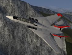
 Splash image | |
 Cockpit view | |
| Type | Interceptor aircraft, Carrier-based aircraft, Fighter aircraft, Interceptor aircraft, Air superiority aircraft, Multirole combat aircraft |
| Configuration | Variable-sweep wing aircraft |
| Propulsion | Twinjet (Jet aircraft, Twin-engine aircraft) |
| Manufacturer | Grumman |
| Author(s) |
|
| FDM | JSBSim |
| --aircraft= |
f-14a f-14b f-14bs |
| Status | Advanced production |
| FDM |
|
| Systems |
|
| Cockpit |
|
| Model |
|
| Supports |
|
| Development | |
| Website |
|
| Repository |
|
| Download |
|
| Liveries |
|
| License | GPLv2+ |
|
| |
The Grumman F-14 Tomcat is a fourth-generation, supersonic, twinjet, two-seat, variable-sweep wing fighter aircraft. The Tomcat was developed for the United States Navy's Naval Fighter Experimental (VFX) program following the collapse of the F-111B ![]() project. The F-14 was the first of the American teen-series fighters, which were designed incorporating the experience of air combat against MiG fighters during the Vietnam War.
project. The F-14 was the first of the American teen-series fighters, which were designed incorporating the experience of air combat against MiG fighters during the Vietnam War.
The F-14 first flew in December 1970 and made its first deployment in 1974 with the U.S. Navy aboard USS Enterprise (CVN-65), replacing the McDonnell Douglas F-4 Phantom II. The F-14 served as the U.S. Navy's primary maritime air superiority fighter, fleet defense interceptor and tactical reconnaissance platform. In the 1990s, it added the Low Altitude Navigation and Targeting Infrared for Night (LANTIRN ![]() ) pod system and began performing precision ground-attack missions.
) pod system and began performing precision ground-attack missions.
The Tomcat was retired from the U.S. Navy's active fleet on 22 September 2006, having been supplanted by the Boeing F/A-18E and F Super Hornets. As of early 2015, the F-14 is in service with only the Islamic Republic of Iran Air Force, having been exported to Iran in 1976, when the U.S. had amicable diplomatic relations with Iran.
There are two variants modeled in FlightGear, both available in FGADDON.
- F-14A with the PW-TF30-414
 engines which are susceptible to compressor stall and underpowered for the airframe)
 - F-14B with the GE F110-GE400 engines improving power and reliability.
Primary Instruments
VDI

The F-14 uses a Vertical Display Indicator (VDI) as the primary attitude reference instrument; there is a standby ADI just to the right.
The center screen has a top part representing the sky and an artificially generated ground representation. When performing a carrier landing there will be flight director bars shown to reference the vertical deviation from the glideslope and deviation from the center line. Carrier landings require the right TACAN channel to be selected (for the carrier) and the ARA-63 to be turned on. When the primary nav is tuned to a civilian ILS frequency this will also be shown on the display although the ARA-63 specific carrier lights will not illuminate
The lights on the side of the VDI that are relevant for a carrier landing are
- LANDING CHK - displayed when between 6 nm and 4.5nm from from carrier and tuned correctly
- ACL READY - displayed when tuned correctly and system operating
- AP CPLR - displayed when system operating and within correct altitude. The AP CPLR system is not available.
- WAVE OFF - displayed when landing should be aborted as outside of the parameters for a good landing.
- 10 SECONDS - displayed when about 10 seconds from touchdown trap
Other lights on the VDI
- AP REF - Autopilot operating
- REDUCE SPEED - Overspeed for flaps; or over the speed bug on the ASI
- ALT LOW - below alt bug on Altimeter
VDI Controls
There are controls for
- HUD BRT - HUD Brightness
- VDI BRT - VDI Brightness
- VDI CONTR - VDI Contrast
- FILTER - Changes the color of the HUD between red and green
- HUD TRIM - non operational
- VDI TRIM - non operational
HUD Lights

The HUD lights contains three sections; from left to right
- AoA Indexer
- Warnings
- ECM/RWR status
AoA Indexer
The AoA Indexer has three lights; out of which up to two can be shown at any one time. These lights are illuminated whenever the gear is down.
If the indexer lights flash it indicates that the hook isn't down; unless the HOOK-BYPASS switch on the right console is selected in which case the lights will always be steady.
The basic logic is that green indicates too high AoA and slow, amber is optimum and red is low AoA too fast. The light combinations are as follows:
- Green V - Airspeed SLOW: AoA too high (over 16°)
- Green V and Orange O - Airspeed SLIGHTLY SLOW: AoA starting to get too high (14.5° to 16°)
- Orange O - OPTIMUM ON SPEED: (the doughnut) - this is the ideal AoA for an approach i.e. between 14.5° and 15.5°. Normally the aircraft is trimmed for pitch on the final approach and primarily throttles are used to control the AoA
- Red upside down V and Orange O - Airspeed SLIGHTLY FAST: AoA starting to get too low (14.0° to 14.5°)
- Red upside down V Airspeed FAST: AoA too low (below 14°).
The airspeed guidance is secondary; it is the AoA that is important.
Warnings
- WHEELS - Landing gear not locked and down - displayed when flaps are down and throttle below 80%
- BRAKES - Wheel brakes are engaged; ⇧ Shift+b to disengage.
- NWS ENGA - Nose Wheel steering is active (below 80 knots)
- AUTO THROT - APC has disengaged abnormally.
Caution Warnings

There is a set of caution warnings that can be shown on the panel on the left console. When a light illuminates on the caution panel the MASTER CAUTION on the glareshield will also illuminate until pushed. Once pushed the caution panel warning will remain and the MASTER CAUTION light will be extinguished.
Relevant warnings;
- START VALVE - the engine crank selector on the engine controls panel has been set whilst the engine is running
- L INLET - malfunction in the Left Inlet system
- R INLET - malfunction in the Right Inlet system
- OIL PRESS - oil pressure on at least one engine is below the minimum.
- L RAMPS - malfunction in the left ramp system
- R RAMPS - malfunction in the right ramp system
- L GEN - Left generator inoperable (i.e. engine RPM below operating speed)
- R GEN - Right generator inoperable (i.e. engine RPM below operating speed)
- LAD / CANOPY - Ladder and/or canopy is open or not correctly latched closed
- BINGO - The fuel has fallen below the Bingo bug as set on the fuel gauge
- HYD PRESS - One of the hydraulic systems is below the minimum operating pressure (1800 psi). Use the hydraulic gauge to determine which system isn't functioning. Normally the Bidirectional transfer pump will keep provide pressure to the other hydraulic system from the good hydraulic system; unless the HYD TRANSFER switch on the right console is set to SHUTOFF'
- L FUEL PRESS - The fuel pressure in the left engine is low
- R FUEL PRESS - The fuel pressure in the right engine is low
- L FUEL LOW - Low fuel in the left engine tanks
- R FUEL LOW - Low fuel in the right engine tanks
- TRANS/RECT - The trans/rect is not operating correctly to provide DC power. This is also shown when using external power
- LAUNCH BAR - Illuminated when insufficient power (< 85%) when the launchbar is engaged for a catapult launch
Engine Gauges

Right Console

ARA 63 Control
Has no effect
Air Condition
Use to control the cabin pressure and temperature. Cabin pressure will be maintained according to the correct schedule. Using Cabin press dump will de-pressurise the cabin. Air source needs to be selected to allow cabin pressure and windshield air to function.
Ext Environment
The windshield air can be used to clear the windshield from frost and internal fogging.
Caution Advisory
Illuminates warnings using different colours to indicate severity; cautions are orange and advisories are lighter.
Master Light Panel
Controls the aircraft lighting
Master Test
Only light test LTS is operational. If successful (and it always will be) the green GO will illuminate. All other tests will result in a NO GO warning
Master Generator Panel
Used control the engine generators and the emergency hydraulically powered electrical generator.
Setting the Emerg generator to off and turning both generators off will result in no electrical power to the aircraft even when both engines are running.
Hyd Transfer Pump
Use to shutoff the emergency transfer between the two hydraulic systems.
If you have the an engine shutdown the hydraulic system will be powered by this pump; if you set the pump to SHUTOFF then the hydraulic system for the shutdown engine will have no pressure.
Keyboard controls
Flight controls
| Key | Function |
|---|---|
| Home | Increase elevator trim |
| End | Decrease elevator trim |
| ] or f | Lower flaps |
| [ or ⇧ Shift+f | Raise flaps |
| Ctrl+b | Toggle speed brakes |
| k | Increase speed brakes |
| j | Decrease speed brakes |
Automatic flight controls
| Key | Function |
|---|---|
| Ctrl+a | Toggle autopilot altitude mode |
| Ctrl+s | Toggle APC (Landing Automatic Power Control) |
| Ctrl+h | Cycle autopilot heading mode |
| Ctrl+t | Aircraft flight control systems|AFCS] (Defaut Attitude Mode) |
| * | Engage AFCS Altitude Mode |
| Ctrl+y | Toggle ground spoilers armed |
HSD - radar and RWR
| Key | Function |
|---|---|
| h | Cycles through HSD modes: radar - compas - ECM (RWR) |
| ⇧ Shift+e | Decrease Radar Range |
| ⇧ Shift+r | Increase Radar Range |
| Ctrl+q | Toggles Radar Standby Mode. In standby mode the radar doesn't emit and the "STAND BY" words are displayed on the HSD screen when in TID mode. |
Carrier operations
See also Howto:Carrier, Carrier over MP as well as a detailed carrier landing howto for the F-14 Tomcat.
| Key | Function |
|---|---|
| ⇧ Shift+o | Lower the hook |
| o | Raise the hook |
| ⇧ Shift+l | Engage launch bar (keep holding until engaged) |
| ⇧ Shift+c | Release catapult |
Weapons
| Key | Function |
|---|---|
| Ctrl+w | Cycle through master arm switch modes (see master arm switch in cockpit). |
| w | Cycle Stick Weapon Mode Selector (see Weapon Mode knob selector on side of joystick in cockpit). Four positions: Off, Gun, SW, SP-PH. |
| Ctrl+m | Toggle AIM-9 selection (must have at least one AIM-9 loaded through Tomcat Controls/Fuel & Stores menu) |
| e | Trigger M61A1 Vulcan gun or AIM-9 missiles (depending on stick weapon mode selection) |
Flaps

The F-14 has three different types of lift augmentation on the wings. Flaps, Auxiliary Flaps and Slats.
Maneuvering flaps and slats are automatically activated by the CADC to improve performance at high AoA and lower speeds. The maneuvering flaps are disabled when wings are swept outside of the permissible region for flap or slat deployment.
In the picture the slats are at the front, the spoilers on the top, and the flaps at the back. The auxiliary flaps are next to the fuselage and the main flaps are behind and below the spoilers.
Wing Sweep

Full aerodynamic affects of wing sweep are modelled. The Wing Sweep can be controlled via the keyboard or by using the Sweep gauge in the cockpit. Use the mousewheel over the sweep angle indication to adjust the required angle of sweep. The legends to the right of the wing sweep gauge can be clicked to any of the possible modes.
The CADC will provide automatic wing sweep based on Mach number. The wings cannot be swept further forwards than the CADC automatic value (to protect the airframe).
The main flaps operate until the wings are swept to 55 degrees; the auxiliary flaps are only available with the wings swept to 22 degrees. Interlocks operate to prevent flap deployment with unsuitable wing sweep.
It is possible to land with fully swept wings; however this should only be used in emergency situations as the landing speed is significantly increased.
| < | Sweep Wings Forwards |
| > | Sweep Wings Aft |
| = | Wing Sweep to Automatic |
Miscellaneous
| c | Toggle canopy and access ladder |
| u | Toggle refuelling probe, three states |
| Ctrl+o | Toggle oversweep (on ground only, otherwise sweep is automatic) |
| Ctrl+v | Toggle between RIO (Radar Intercept Officer) and pilot view |
Gallery
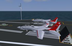
F-14 USS Carl Vinson Multiple Cat Launch
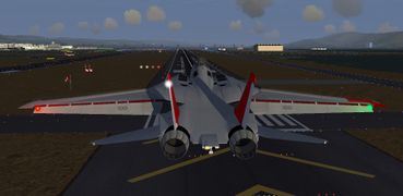
F-14 final approach KSFO
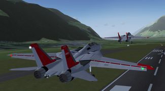
F-14 Formation Takeoff (LSGS) Sion
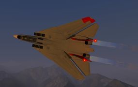
F14 high speed pass
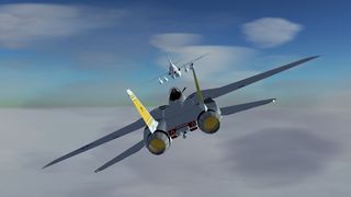
F-14 with wings fully swept
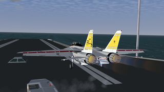
Locked in catapult, flaps set, full afterburner, ready for take-off.
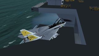
Going below deck on the elevator.
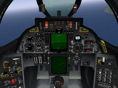
The pilot's "office".
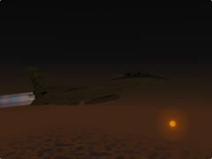
A nice dusk scene with the F-14.
Air-to-air refueling with the F-14B.


Aircraft help
Engine Start
The engines can be quickstarted from the Tomcat Controls menu.

To perform a manual engine start, follow the instructions below. It is usual to start the right engine first to ensure that the flight hydraulics system is pressurized first.
Engine start procedure:
- Ensure that external air is connected (Tomcat Controls menu, Ground Services dialog)
- Ensure that the fuel shut off valves are pulled out for the engine to be started. (Upper left and right of the glareshield)
- On the Engine Controls panel (left console next to the throttles) select Engine Crank (L or R)
- As the engine spools up the hydraulically powered emergency electrical generator will provide backup power
- When the engine reaches 18% RPM push in the appropriate fuel shutoff valve.
- Monitor EGT and if the value goes above 1200 Degrees C shutdown the engine using the fuel shutoff valve (this will never happen with the current engines model)
- Repeat the process for the left engine.
Engine Shutdown
Ensure that the wings are correctly swept, flaps raised and parking brake engaged.
Pull both of the fuel shutoff valves on the glareshield. These are the yellow and black striped items on the glareshield picture.
Once the fuel shutoff valve is pulled the appropriate engine will spool down and stop. When both engines are stopped there will be no hydraulic and electrical power and the cockpit will become dark.
On Shore Takeoff
- Ensure wingsweep is set to automatic and wings are not overswept.
- Check air brake in.
- Use the Tomcat Controls menu, Fuel and Payload dialog to set the required fuel load and payload
- Select up to 25 degrees of flaps depending on the aircraft weight.
- Release parking brakes (Shift-B)
- Select MIL thrust; or afterburners if conditions dictate. It is usual operating procedure on an F-14B to not use afterburners on take off unless heavily loaded as in the event of engine failure after rotation the resulting yaw moment is likely to result in an uncontrolled departure.
- At around 145 knots pull back on the stick until the nose raises at which point maintain stick pressure and when 250 feet AGL raise the gear. By 200 knots the flaps should be fully retracted. Note that as the flaps are retracted the longitudinal balance of the aircraft changes and it will tend to pitch down slightly which should be corrected by using the pitch trim.
Hydraulics System
The F-14 has two separate hydraulic systems; identified as the Flight System and the Combined System. The flight system powers the primary flight controls and surfaces, and the combined powers everything else.
Both hydraulic systems are powered by engine driven pumps. There are two backup systems for the hydraulics in case of an engine (primary) pump malfunction. The first of these is a Bi-Directional transfer pump that can powere one system from the other system. The second method is an electrically powered pump. The electrically powered pump has its own small reservoir - so once powered on the electrically powered pump should not be powered off as the hydraulic fuel expands and is lost - so there may not be enough fluid remaining in the reservoir to allow the pump to start.
When there is insufficient hydraulic power the powered items will no longer function; so in the event of a dual engine flameout the flight controls will be inoperable.
Sufficient hydraulic pressure for smooth flight control inputs should be available with one engine windmilling at 18% rpm or two engines at windmilling at 11% rpm.
References: F14-AAD-1 p2-68 to p2-76
Electrical System
The F-14 electrical system is modeled sufficiently well to provide all visible effects.
There is a generator on each engine powered by a Constant Speed Drive (CSD) with emergency hydraulic generator that is powered by the combined hydraulic system.
- Main generators drop off at 55% N2.
- Emergency generator drop off at 11-12% RPM.
- Engine ignition not available below 10%
- Emergency generator 1kva or kVa essential AC and Buses No1 and No2. and AFCS
- When hydraulic transfer pump operating and sufficient pressure emergency power will drop to 1kVa mode and power only the essential AC and Dc No. 1 buses.
In the model on the left main bus and the DC essential bus are used; however upon loss of electrical power from the main bus the non-essential will no longer be powered (e.g. the HUD, VSD, HSD).
References: F14-AAD-1 p2-68 to p2-76
Autopilot Operation
- The main mode is Attitude Hold Mode, Ctrl+t. Other Modes need this main mode activated before being selected. Switching off Attitude Mode disables all other modes . When in Attitude Mode, the autopilot disengages whenever a certain pressure is put on the stick, and it re-engages when the stick is back in the centre position. Attitude Hold Mode will hold pitch attitudes up to plus or minus 30 degrees, and bank angles up to plus or minus 60 degrees.
- It shall be switched off for aerobatics and inverted flight.
Autopilot Altitude Mode
- Once in the Attitude Mode, you can select Altitude Mode by hitting Ctrl+a, then the AP REF indicator, (left of the VDI) will illuminate, when at the desired altitude using normal stick control, engage by hitting * (asterisk). The autopilot will then maintain your altitude.
| Caution At high speeds, it is imperative to stabilize your aircraft prior to engaging Altitude Mode |
Autopilot Heading Mode
- Once in the Attitude Mode, you can select Heading Mode by hitting Ctrl+h. After manoeuvring the aircraft into the desired reference heading, release the control stick at a bank angle of less than 5 degrees. The autopilot will then hold the aircraft on the selected heading.
- To follow a route manager route; activate the route from the route manager and press Ctrl+h a second time or select "GT" on the AFCS panel just below the throttles.

- Autopilot needs SAS channels to be engaged, which is the default. SAS Pitch and Roll channels may be disengaged by actuating switches located on the AFCS (Automatic/Analog Flight Control System) panel.
Approach Power Compensator (APC)
- The APC is a closed loop system that automatically regulates engine thrust to maintain on-speed (orange donut in the AoA indexer) for carrier recoveries and FCLP.
- Type Ctrl+s to toggle the APC on/off. APC is also disengaged by setting the throttles to MIL, (98 percent rpm) or idle, (68 percent rpm) or raising the landing gear handle or when weight on the wheels.
- When disengaged the AUTO THROT caution light, (on the left side of the HUD) illuminates for 10 seconds.
(NATOPS 8.5.3) guidelines for APC use
Practice is required to develop the proper control habits necessary to use APC. For the APC to perform satisfactorily, smooth attitude control is essential. Large, abrupt attitude changes result in excessive power changes. APC use is not recommended in gusty conditions. The APC will overcontrol AOA fluctuations resulting in large airspeed and/or glideslope deviations.
As the initial turn from the 180 position is made, the aircraft will momentarily indicate up to 2 units slow. The APC will adjust power to correct back to on-speed condition throughout the remainder of the turn. Upon rollout on glideslope, the pilot must override the tendency for the nose to pitch up by maintaining slight forward stick. The aircraft will indicate 1 to 2 units fast, which will slow to on-speed within 5 seconds.
The use of DLC in conjunction with small attitude changes to maintain glideslope will minimize AOA deviations and result in optimal APC performance. Timely use of DLC can also be used to more rapidly correct from a fast or slow condition.
Close-in corrections are very critical. If a high, in-close situation develops, the recommended procedure is to stop the meatball motion and not try to recenter it. A low, in-close condition is difficult to correct with APC and often results in an over-the-top bolter. It may be necessary to disengage or manually override APC in order to safely recover from a low in-close situation. Throughout the approach, the pilot should keep his hand on the throttles in the event APC disengages inadvertently. A smooth throttle transition from AUTO to BOOST mode can be achieved by depressing the CAGE button on the outboard throttle grip.
Notes
- Approaches that result in steep bank angles (greater than 30!) and/or short groove lengths should be avoided be- cause of the large thrust reductions required and the short periods of time available to make proper corrections.
- Disengagement of APC by any means other than the throttle MODE switch, will result in illumination of the AUTO THROT light for 10 seconds.

Spoilers

Each wing has a set of spoilers that are used to augment the roll rate during normal flight controlled by the CADC when wings are swept forwards more than 55 degrees. The spoilers can also act as brakes to provide extra retardation upon touchdown.
To engage ground spoilers set the ANTI SKID SPOILER BK switch on the bottom of left vertical console to BOTH or use Ctrl+y. After touch down and the throttles pulled to idle, then the spoilers are fully deployed.
Weapons operation
At the moment, only the gun and the AIM-9s are operational, others ordinances are displayed under the wing, their weight is correct but they aren't usable.
- Gun: At startup, the ammunition store is filled with 675 round. There is an option on the Fuel and Stores dialog in the Tomact Controls Menu to allow the gun to be reloaded
To fire the M61A1 Vulcan:
- Select HUD A/A Mode on the Display panel, on pilot's right console. A multikey shortcut is also available :AHa. Having the HUD in this mode is not mandatory however when the HUD is in the right mode the guidance symbology will assist with target identification and aiming.
- Select Gun mode with the Stick Weapon Mode Selector (w). A pipper, the G symbol with a number showing approximately the remaining rounds x 100 and a closure rate scale are displayed in the HUD. The closure rate scale is active only if a target is locked by the radar with TWS AUTO mode (diamond on the HUD).
- Switch Master Arm on cycle with CTRL-w, the X on the G symbol means Master Arm off or in training mode.
- Press e to fire the gun.
- Sidewinders: Crudely modeled on AIM-9L available data.
- Select a weapons set using the menu: Tomcat Controls > Fuel and Stores: "FAD light" has 4 sidewinders, "FAD", "FAD heavy" and "Bombcat" have 2 of them.
- Select HUD A/A Mode on the Display panel, on pilot's right console. A multikey shortcut is also available (:AHa).
- Select SW mode with the Stick Weapon Mode Selector (w).
- Switch to the RIO view (Ctrl+v).
- Select pylons 1 and 8, down position, on the Armament panel, on RIO's left console. A shortcut toggles these two switches so you can select or deselect all AIM-9 in one keyboard stroke (Ctrl+m) without leaving pilot's view.
- Switch back to the pilot's view (Ctrl+v).
- Switch Master Arm on, you hear the search signal of the seeker head, a low volume buzz sound.
- Now prior to be fired, the AIM-9 must have a lock on a target. Multiplayers, AI aircraft, and AI tankers can be locked. The minimal lock distance is 10 NM, the target must be approximately inside a 80° cone centred on datum line. When locked, the signal buzz volume becomes louder. For best results try to shoot (e) at a 3 to 6 NM range and with the target centred on the aircraft velocity vector. The missile will explode at the smaller distance possible. However if this distance is above 70 meters, it will continue its trajectory without guidance.
Pilot's Cockpit

Displays Control Panel
- The Display Control Panel is located on the right side of the pilot's main panel, under the Hook lever. The 3 botom switches respectively turn the VDI, HUD and HSD displays on/off. The HSD MODE switch is also available, it selects NAV or TID or ECM mode. This can also be achieved by cycling through these 3 modes with the h key.
- VDI: Vertical Display Indicator. Shows the aircraft attitude in roll and pitch, with an artifitial horizon and magnetic heading.
- HUD: Head UP Display.
- HSD: Horizontal Situation Display. HSD shows either:
- in NAV mode: compas with navigation indications,
- in TID mode (Tactical Information Display): an horizontal representation of the tactical situation (that is information provided by the RIO from what he sees in his radar displays).
- in ECM mode: a representation of radar threats around the aircraft.
VHF
- Located on the RIO's left console, 3 bands: 30-88 MHz, 108-174 MHz, 225-400 MHz. Modes TR and TR-G set COMM1. Mode DF sets NAV1, that is Direction Finder displayed with the single needle in both BDHIs (Bearing, Distance, Heading Indicator) . You have Comm *or* DF. Storing frequencies (up to 20 channels) a - PRESET select the desired channel, b - READ tune the desired frequency, c - LOAD stores the frequency in the previously selected channel.
UHF
- Located on the pilot's left console, 225-400 Mhz. ADF is not enabled on this radio.
Dual Control (RIO)

Dual control over Multiplayer allows a RIO to operate the radar range and mode.
On the ground during the startup phase the pilot handles all of the engines, control surfaces, and other on-board checks and the RIO looks after radar and a few other systems. The RIO usually does most of the communication with ATC.
The RIO will find the targets and designate them; it's then up to the pilot to check that it is the correct target and release the weapon. After weapon release it becomes the RIO's job to perform laser guidance and monitor the missile progress.
Within Flightgear the target designation is automatic as most of the time you don't have a RIO.
So a Dual Control RIO will take responsibility for the following:
- Operating the radar mode and range
- Communication with ATC
- Keeping a good watch on the Radar and ECM screens and out of the window.
- Advising the pilot of fuel status, and monitoring the airspeed and altitude (especially during an engagement with another aircraft). Voice comms using FGCOM or another method is recommended as things happen too quickly for text chat to be much use (and besides the pilot will usually be busy with the controls).
External links
- F-14 Tomcat
- Link to FGAddon repo
- Development page, additional information, and alternative download
- Post about the updated F-14B (flightgear.org)
- F-14 Tomcat (GlobalSecurity.org)
- F-14 Tomcat (FAS.org)
- Home of M.A.T.S.
- NATOPS Landing Signal Officer Manual
- YouTube video about F-14 air combat maneuvering against the T-38, A-4 and F-4 at Naval Air Station Miramar, San Diego (the real TOPGUN).
| |||||
| |||||||||||||||||