Radio beacons

Standing blindfolded in the middle of a field. In a distance a friend is shouting "I am here!". You turn around till you hear your friend best and start walking towards the sound. When there are two friends (with distinctive voices) and a map telling you where they stand, you can even figure out about where you are on that map. This describes how a Non Directional Beacon (NDB) works.
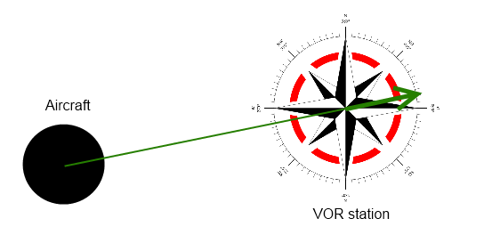
If the friends do not like to shout all the time, they can lay down numbered ropes around them. Each rope leads directly towards a friend. The numbers on the rope are the same numbers as the degrees on a compass. So by comparing the numbers on the ropes that cross the place where you are standing, you know where you are. This describes how a VHF Omnidirectional Range (VOR) works.
But what if you want to know where you are and you have just one friend? Then the friend had to make knots in the ropes telling how far away you are. This describes how a VOR-Distance Measuring Equipment (VOR-DME) works.
A radio is a generic term for the transmission of electromagnetic waves. In the above comparisons, a radio beacon is the one that is shouting or that is laying out the ropes. A beacon can include information, it can even send out music. Two-way communication is possible where the equipment on-board questions equipment on-ground or the beacon is used for ATIS or Tower communication.
Radio beacons enable Radio navigation and IFR taking away the need for visual landmarks. Navigation at night and at high altitude are possible.
NDB


A Non-Directional Beacon (NDB) is the most basic type of radio beacon. The equipment on board of our aircraft will have to figure out where it is. Any (music) radio station is also a NDB. The typical frequencies of a NDB can be found on the AM Medium band (530 kHz to 1700 kHz) but during flight planning we shall discover NDB's outside this range.
It is possible to calculate the distance towards a NDB station. For that a pilot flies on a 90 degree angle opposite the station (one wing-tip pointing towards the station). The pilot measures the time it takes to fly a number of degrees on the compass. From the time it takes, the number of degrees and the ground speed the pilot can calculate the distance towards the station.
Very modern receivers can estimate the distance towards a NDB station by the azimuth towards the station.
In the Americas the navigational NDB's operate 530 kHz to 1700 kHz with 10 kHz increments. The rest of the world uses 531 kHz to 1602 kHz with 9 kHz increments. NDB's outside these ranges most probably serve also other purposes, like music stations or DGPS stations.
The range of a typical NDB can be up to 75 NM. When using LFR the range can be bigger but less accurate. The higher the aircraft the longer the range.
A NDB is sensitive for weather and ground influences, it can get reflected and distorted making a bearing less reliable. As a distance measuring tool the NDB is not quite suited. But it is good enough to find fixes on a map and can be used for point-to-point navigation. It is cheap to operate.
LFR
The Low Frequency Radio Range (LFR) beacon is a directional beacon that operates at a frequency of 190 to 535 kHz, the long wave frequency and a bit above. Across the world there are plenty of NDB radio beacons in that range but they do not operate as LFR stations. The long wave frequency is known for it's long range due to sky layer reflections but reflected signals are very unreliable for navigation.
RDF
There are two ways to figure out where the NDB is relative to the aircraft. Rotating an antenna manually until finding the direction of the strongest signal (loudest transmission) or have this done automatically (or electronically). The equipment (or person) to do so is called a Radio Direction Finder (RDF).
ADF
An ADF is not a radio station, its the the equipment on board of the aircraft to perform RDF automatically, the Automatic Direction Finder (ADF). A widely used unit (for example in our C172P) is the Bendix/King KR-87.
The display unit of an ADF is called MDI (Moving Dial Indicator). Usage and functionality is pretty simple: the needle points to the direction of the NDB station. If the needle points directly upwards, this indicates the plane is pointing towards the station. The compass disc does not rotate automatically and can be adjusted using the knob on the bottom left labelled "HD". If aligned to the magnetic compass, you can read the QDM (magnetic bearing to the sender) from the scale.
A more complex display unit is the RMI (Radio Magnetic Indicator). It has a roatable compass disc that is working like a directional gyro. It saves you from the need to readjust the compass disc in flight. In addition to that, the RMI can process the output of two navigation receiver units, for example 2 VORs or one NBD and one VOR. If the ADF is turned on, the needle for the ADF will point to the station like with the MDI. The obvious advantage of the RMI is, that you can directly read the QDM.
If the second RMI needle is active, it is perfectly suited to estimate your position by doing cross-bearing (see picture at the start of the page).
Often NDB stations are called ADF stations but that is technically incorrect.
VOR

A VHF Omnidirectional Range (VOR) is a radio beacon that sends out a special signal making it possible for the receiving equipment to figure out the radial of the beacon. The heading (-line) towards the beacon is called a radial.
If a NDB shouts "I am here!", the VOR shouts "To come to me you would have to fly *this* course!".
The VOR uses frequencies in the the Very High Frequency (VHF) range, it uses channels between 108.0 MHz and 117.95 MHz. It is spaced with 0.05 MHz intervals (so 115.00; 115.05; 115.10 etc). The range 108...112 is shared with ILS frequencies. To differentiate between them VOR has an even number on the 0.1 MHz frequency and the ILS has an uneven number on the 0,1 MHz frequency.
- So 108.0; 108.05; 108.20; 108.25; 108.40; 108.45 would be VOR stations.
- and 108.10; 108.15; 108.30; 108.35; 108.50; 108.55 would be ILS stations.
The VOR beacon tells the equipment what course to fly to intercept the beacon.
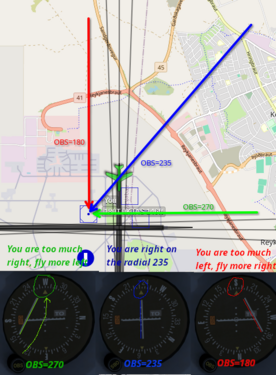
Relation of OBS (selected course) and CDI (Course deflection Indicator) to position of the aircraft

A VOR station is most often also used for communication (ATC) with the airfield. ATIS, ground, tower etc. The omnidirectional signal is transmitted on a modulated continues wave containing the identifying Morse code. The signal contains a AM signal that can be used for voice or ATC. The signal is FM modulated and the lag (delay) between the AM and FM signal identifies the radial.
Typically the transmitted radial is oriented to True North.
Very modern receivers can estimate the distance towards a VOR only station by the azimuth towards the station.
The range of the VOR signals depend on the type used.
- Terminal (T)
- 1,000 up to and including 12,000 AGL out to 25NM.
- Low Altitude (L)
- 1,000 up to and including 18,000 AGL out to 40NM.
- High Altitude (H)
- 1) 1,000 up to and including 14,500 AGL out to 40NM.
- 2) 14,500 up to and including 60,000 AGL out to 100 nm.
- 3) 18,000 up to and including 45,000 AGL out to 130 nm.
- The higher the aircraft the longer the range.
There has to be a clear line-of-sight with the beacon. If there are mountains or other obstructions the VOR signal can not be received.
The beacon can be received mostly with a clear line of sight, but can also be received if obstructed, via various means: diffraction, trophosperic scatter, tropospheric ducting etc.
The range depicted above is only orientative. In real life situations, radio signal propagation characteristics can expand or reduce the range.
While it is more expensive to operate a VOR station compared with a NDB the benefits are obvious. The signal is less hindered by unwanted reflections and other interferences, when the signal is received it is accurate, it takes away confusion about North, since it's oriented True North, it can be used for automated flight and the receivers are more reliable.
VOR-DME

Distance Measuring Equipment (DME) does not use the same frequencies as a VOR!. See | the wikipedia page for a detailed description. A DME tells the equipment on board of the aircraft the distance towards the station. There is two-way communication between the equipment on-board and the DME station to calculate the result.
While a VOR can be a stand-alone beacon, a DME will be paired with a VOR, a VOR-DME. Both senders will contain information about the other and tuning will be automatic. If the VOR station (of a VOR-DME) fails it defaults to a stand-alone DME.
For position finding only one VOR-DME station is needed since it gives the radial towards the station and the distance. Knowing the position of the VOR-DME station on the map will give the position of the aircraft on that map.
ILS
An Instrument Landing System (ILS) beacon can be used as a NDB beacon (with some receivers) but it's range is limited and depends very much on the position of the aircraft towards the station (and runway). The LOC signal of an ILS transmits only one radial, the heading towards the runway, in one direction. It should only be used as a system for landing and not for navigation. The glideslope component transmits a signal in the 300 MHz band, while the localizer is sharing the lower VHF (108-117.95 MHz) with the VOR's. The localizer can also be used on the backcourse, if approved by local authorities, especially when a go-around maneuver is performed.
TACAN
The military uses a slightly different system as the civilian version. The military uses something named TACAN that operates in the frequency band 960-1215 MHz overlapping the DME frequency range. It combines a VOR-DME and includes an azimuth feature that provides more accurate navigation.

VORTAC
Often the VOR-DME part of the TACAN is also made available for civilian navigation. If so, the beacon is called a VORTAC, but the use is as a normal VOR-DME, in the normal frequency range. The range of the beacon varies. Most have the same range as a VOR-DME but many will have different ranges. Sometimes the VORTAC defaults to a NDB-DME refusing to provide a radial.
- If possible plan a route without a VORTAC since they can be quite unpredictable.
Fix
Not a radio beacon, but a combination of them. On aeronautical maps there are fixes. Fixes are usually identified with a five letter code. Another word for a fix is Intersection. A fix is a place that is crossed by two or more easy radials from a VOR or bearings from a NDB, some fixes are on a radial of a VOR-DME and a specific distance. Typically the easy bearings are 45 degrees intervals on a compass rose, but there are plenty of fixes that use other intervals. It is sometimes a bit of guessing what beacons should used for a fix, most often it's the two nearest ones.
Marker beacons
Runways used to have three vertical directed radio beacons in-line with the runway to aid landing, the marker beacons. It was often combined with the ILS
- Outer marker - Typically placed at 4 NM from runway
- Middle marker - Typically placed at 3500 feet from the runway
- Inner marker - Typically placed at 1000 feet from runway. The aircraft should be at decision altitude/height and the pilot should perform the missed approach procedure if the runway is not visible.
Distance from runway varies a lot. On many airfields the markers have been replaced with an ILS and/or VOR-DME. The outer marker is sometimes combined with a NDB.
Airways
An airway is a predefined flightpath. It is composed like a normal flightplan of legs between VOR, NDB and fixes. Most airways are in controlled airspace. Airways have names and make the creation of a flightplan easier. For a flightplan only the legs towards and from the airway have to be defined.
Further reading
External articles
- http://en.wikipedia.org/wiki/Radio_navigation
- http://en.wikipedia.org/wiki/Radio_beacons
- http://en.wikipedia.org/wiki/Differential_GPS
- http://en.wikipedia.org/wiki/Wide_Area_Augmentation_System
- http://en.wikipedia.org/wiki/Local_Area_Augmentation_System
- http://en.wikipedia.org/wiki/Airway_%28aviation%29
- http://www.dxinfocentre.com/ Providing a collection of stations