Improving Glider Realism
This article lists areas that have a significant impact on soaring realism.
Gliders
This section reviews the design issues affecting the user aircraft.
Flight Model
A realistic Flight Dynamics Model is key to a good glider experience. Especially the correct gliding performance as well as handling in different conditions significantly affects glider realism.
Most gliders available for FlightGear today (06/2023) use JSBSim with lift/drag functions based on published gliding polars, which are often available from the flight manual.
While information about handling, stall behaviour etc. is often available from the flight manual, specific data e.g. lift/drag and rotational moments is lacking. Using OpenVSP or similar can help here, but are typically quite challenging to use and require a significant amount of knowledge about aerodynamics. Additionally, scientific papers, although only available for a minority of glider aircraft, can help getting the general direction correctly (both combined with OpenVSP as well as "stand-alone").
Glider external 3D models
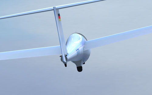
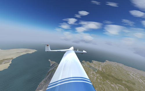
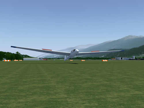
This is the best understood bit of glider simulation... designing a decent 3D model. You can tell if it's any good just by looking at it, although performance plays a part too. For the current FG glider state of the art, here's the ASK21 (April 2017):
Glider cockpit 3D models
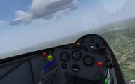
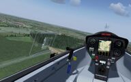
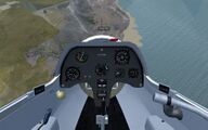
Less well understood, but still not rocket science, gliders need a good 3d model for the cockpit with the panel and the various levers (joystick, flaps, airbrakes, water ballast, landing gear). The current (January 2017) panels are displayed below - already quite well but mostly still lacking important parts such as levers:
Gauges
- See also Soaring instrumentation SDK, a toolkit allowing configuration of advanced soaring specific instruments.
Unfortunately it is not possible to create a decent glider by simply copying across existing instruments from a power aircraft. The minimum instrument set is an altimeter, air speed indicator, and variometer. The variometer (vario) is unique to soaring.
Glider instruments are generally 80mm or 57mm in diameter. This standardisation makes it easier to add/remove/move instruments in the panel.
The mandatory instruments are the altimeter and the air speed indicator. These two and the main variometer are generally 80mm diameter instruments. The panel often includes a 'flight computer' with a digital display showing a variety of flight parameters which also takes up an 80mm 'hole' on the panel. The flight computer often drives a separate 'slave' variometer often in a 57mm hole.
Note: As of 10/2013 there is active development going on to improve FlightGear support for gliding specific instrumentation. More information can be found here and at FlightGear Newsletter October 2013#Soaring Instrumentation Toolkit.
Variometer
At its simplest, a variometer is a rate of climb indicator. However, this pure (uncompensated) indication of vertical speed is very poor for climbing effectively in thermals as the effect of the vertical movement of the air is swamped by the pilot's actions with the control column (so called 'stick thermals'). Since the 1930's, real gliding variometers have used some method to compensate for the climb rate induced by the pilot pushing or pulling on the control column.
It is common for a glider panel to have more than one variometer - the largest (80mm) analogue dial may be displaying Total Energy compensated climb rate (see immediately below) while a smaller dial connected to the flight computer may be displaying Netto or speed-to-fly.
- Total energy compensation. If the glider is climbing, a factor can be subtracted from the indicated lift if the glider is decelerating, and the reverse during descent. So if the glider is neither accelerating or decelerating the absolute rate of climb (or sink) will be shown.
- Potential energy = mass x G x height (or height = energy / (mass x G))
- Kinetic energy = 0.5 x mass x velocity squared
- if in time period 't' the glider goes from height 'h1'..'h2' and speed 'v1'..'v2':
- uncompensated vario reading = (h2-h1)/t
- TE adjustment = height the glider would have gained if it hadn't accelerated / time
- = (change in kinetic energy / (mass x G))/t
- = ((0.5 * mass * v2^2 - 0.5 * mass * v1^2) / (mass x G)) / t
- = (v2^2 - v1^2) / 2Gt where G = 9.81 meters per second per second
- TE reading = uncompensated reading + TE adjustment
- TE reading = (h2-h1)/t + (v2^2 - v1^2) / (19.62*t)
- (all units meters, seconds, meters per second)
- Netto compensation. The design sink rate of the glider at the current airspeed is added to the total energy vario reading, so the variometer actually displays the vertical rate of the air outside the glider. For a perfectly compensated instrument, the vario will show zero in still air regardless of the airspeed of the aircraft
- Speed-to-fly display. Generally in a glider, if the variometer needle moves negative you assume sinking air and speed up. Or if the vario needle indicates lift you slow up and if the lift is good enough you pull up into a turn. So for cruising flight you continually speed up and slow down according to what the vario is doing - this is called dolphin flying and is a particularly efficient way of flying cross-country, giving you more time in lift (because you slow down) and less time in sink (because you speed up). But what is the optimum speed to fly in any given rising or sinking air? To take out the guesswork, some electronic variometers (those slaved from a flight computer) are configured to read in the lift/sink value but indicate positive if you should slow down, and negative if you should speed up. To an uninitiated observer, the gauge looks like an ordinary variometer - even though the computation being performed is more complex, the needle moves up (slow down) and down (speed up) in a natural way, just like an 'ordinary' vario.
In order of complexity, the uncompensated 'rate of climb' vario is the simplest but less useful, the TE vario is still pretty simple but a lot more useful, the Netto vario is a fair bit more complex requiring the gauge to know the glide performance of the glider at every speed and ballast load, and the speed-to-fly vario is fairly complex to code as it has to know the Netto stuff plus tables for the optimum speed to fly at different ballast settings and external lift/sink rates.
Please Note that as of 06/2010 there is now a TE compensated variometer available in FlightGear HEAD: $FG_ROOT/Aircraft/Instruments-3d/glider/vario/ilec-sc7. It has been implemented for the ASK13 glider. (As of 02/2011 there is also a second TE compensated variometer available, implemented for the DG-101G.)
People interested in adding this instrument to other gliders, will want to refer to the README_install file.
Also see:
- http://en.wikipedia.org/wiki/Variometer#Total_Energy_Compensation
- http://soaringlab.blogspot.com/2009/11/total-energy-compensation-explained.html
- http://soaringlab.blogspot.com/2009/11/total-energy-compensation-explained_08.html
- http://www.auf.asn.au/groundschool/variometer.html
- http://www.lsc-schliersee.de/Ausbildung/Streckenfliegen/Dateien/TE-Vario_in_the_Flowfield_of_Thermals.pdf
- http://www.hkavionics.com/Bohli_man/ba_vario1e.pdf
- http://www.borgeltinstruments.com/Gusts.pdf
Flight Computer
Note: As of 08/2012 (FG 2.8) there's a new Canvas subsystem available in FlightGear, which provides support for fully scripted avionics, so that custom avionics, including flight computers and MFDs can be entirely created in scripting space.
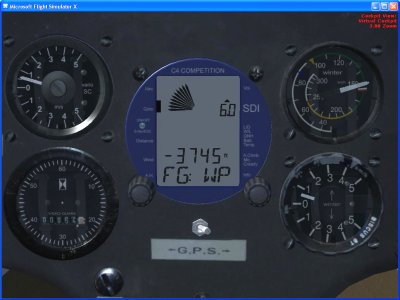
These electronic instruments primarily drive slave variometers of various types (see above) and compute your arrival height at the next waypoint or final destination (for which they are generally connected to a GPS). The screenshot below is taken from the Aerosoft Discus for FSX - this flight computer is the most complex gauge ever created for FSX, containing 3500 lines of code to perform computations then displayed through the simple interface, i.e. the slave variometer needle (top left), the 'petal' variometer needle on the display itself, and the digital numeric displays. The other analogue gauges (ASI, TE vario, engine tachometer) are not connected to the flight computer. An open source implementation of a "gliding computer" is available in the form of XCSoar for Pocket PCs.
For a comparison of some of the more common flight computers, and a list of features, see: http://www.cumulus-soaring.com/flightcomputers.htm
IGC file logger
To compare flights with others, it helps to have a log of your flight in the 'IGC format'. This is a text file with an agreed format, with some header rows and then one-row-per-timestamp for the lat/long/alt.
The specification for the IGC format log file is available on the FAI website.
The full specification has become unbelievably tortuous, but most of the records are optional and an example of a working file would be:
AXXXb21_sim_probe 2.55
HFDTE070608
HFFXA035
HFPLTPILOTINCHARGE: not recorded
HFCM2CREW2: not recorded
HFGTYGLIDERTYPE:DG
HFGIDGLIDERID:B21
HFDTM100GPSDATUM: WGS-1984
HFRFWFIRMWAREVERSION: 2.55
HFRHWHARDWAREVERSION: 2008
HFFTYFRTYPE: sim_probe by Ian Forster-Lewis
HFGPSGPS:Microsoft Flight Simulator
HFPRSPRESSALTSENSOR: Microsoft Flight Simulator
HFCIDCOMPETITIONID:B21
HFCCLCOMPETITIONCLASS:Microsoft Flight Simulator
I013638FXA
B1658174040958N07737022WA0094000940000
B1658214040875N07737069WA0095200952000
B1658254040811N07737136WA0095300953000
... and more B records for the rest of the file
G123456789
IGC files can be uploaded to everytrail.com or can be converted by gpsvisualizer.com for viewing in Google Earth. Also, there's an open source tool available, named "gpligc".
Enviroment lift modelling
This section reviews the requirements for the environment modelling, in particular the simulation of the vertical component of air movement on which gliders depend for soaring flight.
Advanced weather (previously "Local Weather"), which is available since 2011, greatly improves weather realism and simulates thermals as well as ridge lift.
Thermals
Ridgelift
A paper on the efficient calculation of ridge lift is available from Ian Forster-Lewis. This is now implemented in CVS. Ridge lift is enabled by default but may be disabled by using
--prop:/environment/ridge-lift/enabled=0
on the command line or by setting this property at runtime.
The FlightGear issues are also discussed in this forum thread
Wave
Other Open-Source Gliding Simulators
- http://sourceforge.net/projects/slopesoaringsim/ (GPL, latest version from 2006 according to their website)
- http://sourceforge.net/projects/zsim/ (OSG based, latest version from 2019)
- http://sourceforge.net/projects/glider3d/ (latest version from 2008)
- https://github.com/jrgenerative/fixed-wing-sim (uses FlightGear for visualization)
