Howto:Methods to replace the dial gauge bit mapped texture with vectorial objects
In the FIAT G91-R1B project it was necessary to realize high resolution analog gauges (tolerance <1/10 mm) to allow a better visualization of the instruments and therefore a more comfortable simulated flight experience. The creation of high resolution analog gauges required the creation of the instruments with a CAD program called Freecad (very suitable for mechanical and micromechanical parts). FreeCAD is an open source project based on OpenSCAD libraries initially developed for the US Army. Unfortunately Freecad does not contain a .ac converter, but you must first go to Blender via the .obj format and then convert to .ac format. If you want to obtain a resolution of the dial lower than 1/10 of mm it is necessary to use 1024 textures because the gauge has an average dimension between 50-100 mm. Flightgear's airplanes rarely have gauge dials so detailed and so this work has served to show that the Flightgear system is still capable of working effectively with dozens of high-resolution gauges. But sometimes, especially for smaller PCs, it may happen to witness an evident slowdown and in some cases the abort of the program for an evident end of the available resources. To overcome this drawback, a detailed analysis of the causes was made and it was found that the problem was due to the high amount of 1024 textures present in the cockpit instruments. The reason is substantially related to the internal mode of operation of modern GPUs that convert a bitmapped image into vertices that with tens of images with a size of 1024 can lead to the saturation of memory available. Therefore, the solution can be given by using a different paradigm in which the bitmapped image is substituted with an equivalent vectorized image.
Efficiency in converting a bitmapped image into vector
A dial image is essentially an image consisting of 90-95% of empty pixels. Therefore, in this case, it is possible to apply the method of converting bitmapped image in vector. This method is not always advantageous, if the bitmapped image is complex, such as a geographic map, the conversion into vector format, described in this how-to, may not have the desired benefits. Even the characteristics of the bitmapped image can greatly change the quality of the conversion work and therefore it is necessary to make some tests to understand if this is a useful way to solve the problem.
Converting a raster image to vector
In the open-source spirit of Flightgear everything that is explained here must be freely available and without particular constraints on the propiety of the work done. I want to remind you that many converters on the Internet change the terms of intellectual property of the processed content and are therefore not compatible with Flightgear.
For the enhancement of bitmaps in this how-to is proposed Inkscape that is very used by the developers of Flghtgear and often many textures were made with Inkscape (SVG format) and then converted to PNG or via canvas used directly on the surfaces.
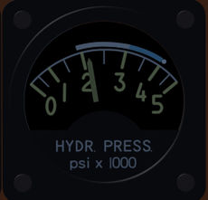
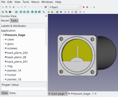
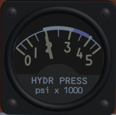
FIAT G91R1B Hydraulic pressure gauge with bitmap dial
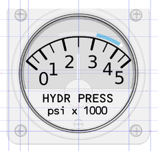
The Inkscape view of the gauge with the four dial layers
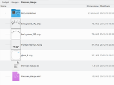
The 4 files (1024x1024) that make up the 4 layers of the pressure meter


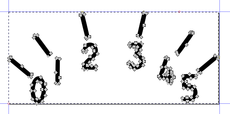
So the main work is to take a PNG or 2D raster image with SVG format and convert it into a vectorized two-dimensional image. Sometimes it may be convenient to transform the vectorized two-dimensional image into a 3D image and this step will be explained as a technique to simulate the characters carved by punching on the knobs.
On the right you can see the appearance of a medium-sized gauge (about 2 inches). As you can see the gauge is made with four bitmapped layers that define the colors and the levels on the surfaces (bottom for the bicolour graduated circle, medium for the description, hight for the arc applied on the glass). Each of these layers also has a different reflectance and light emission properties.
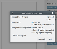
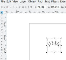
1th step: The image is import to keep the file's DPI
2th step: The image when it is important that it is the same size as the original. This way it will be easily inserted into objects with Blender
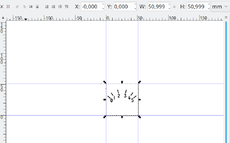
3th step: Select the image and then from the "Edit" menu and execute the command "Resize page to selection"
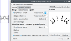
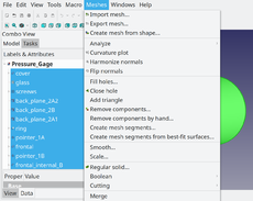
4th step: Selected image, execute "Path" -> "Trace Bitmap" to generate a vectorized image copy
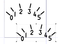
5th step: Copy of the vectorized image
6th step: The page is resized to the vectorized image


The bitmap (The image must be in shades of gray) is load (Steps 1-2-3) and be converted using the "trace bitmap" option of "Path" (Steps 4-5-6). At this point we have a SVG format vectorized object that can be used by Blender. Then take care to eliminate the bitamapped image that has remained under the vectorized image. It is better to take a second step before saving the SVG file, converting the page format to the size of the generated image, in this way it will be easier to manage it in Blender. For this you need to select the vectorized image go to the "edit" menu and then "resize page to selection". At this point the image is ready to be exported in SVG vector format. Normally the vectorization parameters are good, sometimes it is better to change "brightness reduction" according to the thickness to be obtained.
This first phase can be different if, instead of starting from a raster image, we start from an image generated with Inkscape. In this second case, conversion is always convenient to avoid problems with fonts. Inkscape's resolution, at this stage, is enough to ensure a good job. Sometimes I got a more realistic result by doing a first rasterization step of the SVG file at a resolution of 1024x1024 and then I converted the PNG file into vector format.
- NOTE: Attention to scale problems
- It is possible with blender to scale the objects generated in SVG format, but it is not a good practice because if you wanted to resume the gauge to make other changes and additions with Freecad you would need to redo the scalings. It is better always with Inkscape to correctly dimension the drawing. The PNG file has within it the metric and the vectorization and subsequent conversion in SVG preserving this metric. Therefore always proceed in 1: 1 scale if you do not follow this rule the work becomes much longer and more complicated.
Finally we now have an image that can be imported into Blender (but unfortunately, at least for now, not in Freecad!) And applied to parts of the 3D model. This work must be performed for all 4 layers of the example.
Export of the 3D drawing of the gauge from Freecad to Blender
As already mentioned at the beginning of this article, the gauges present in the example are made with the three-dimensional opensource CAD called Freecad. Freecad is now a fairly mature product to achieve a decent quality of 3D objects, especially if the objects were made using machine-made techniques. Blender remains the best solution for making parts that require bent aluminum sheets, such as the fuselage or wings.
In the case of the FIAT G91-R1B all the objects of the cockpit and part of the objects placed on the rider's sides are made with Freecad, this means that dozens of objects have been modeled with a 3D CAD and therefore with considerable precision (0.5-0.1 mm ). Currently this way of proceeding is not usual in Flightgear because the modellers tend to prefer Blender to make all the parts of the model, however in the future, with the constant improvement of Freecad, it may be probable that some modeler will do a project completely in Freecad.
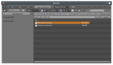
However, once the gauge has been drawn it is necessary to export it to Blender for the subsequent conversion in .ac format. The best solution is to export it in .obj format as this format preserves the individual objects, but not the colors and transparency. In reality it is not important to have these attributes as they will be assigned in the appropriate xml file. It may seem like a complication, but if you want to get a good model you need to work the individual parts that compose it so as to get as close as possible to the real object.
Below are the steps necessary for the transformation into a .obj format of a 3D model created in Freecad:
Open the 3D drawing created with Freecad
Select all the objects that will have to compose the operating gauge
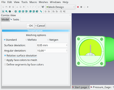
Make the 3D drawing mesh conversion with sufficient resolution
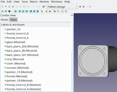
The generated mesh elements cover the whole gauge and show us the quality of the work
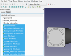
Select all the meshes generated in order to export them in .obj format
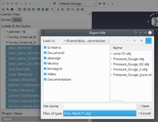
The export in .obj format preserves the individual parts, but not their attributes (color, transparency) that will have to be imposed through the animations in the XML script that loads the gauge


Inserting the image via Blender
The last step is to insert the objects generated in SVG into the gauge imported into Blender. The operation is an approach to objects. SVG objects generated by Inkscape are two-dimensional meshes. These objects should be placed almost in contact with the surface of the guge at a distance of about 1/10 mm. If the distance is less than this value it is possible to generate interference phenomena between the surfaces because the final rendering in Flightgear has a certain tolerance in the measurements due to various causes. It is certainly possible to use other coupling methods, but I do not know if they are convenient at the end. Certainly if you find a better method, this will be treated in this how-to.
Below is a list of the steps necessary to insert an SVG on a gauge generated with Freecad in Blender:
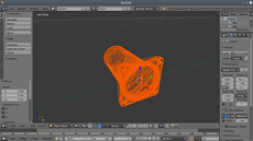
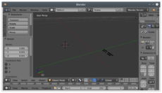
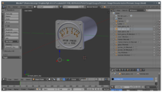
We import the gauge in obj format in Blender. Note the coordinate system adopted that allows the correct positioning of the gauge in the cockpit of the plane
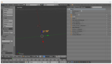
Now we import the SVG object generated with Inkscape which contains the vectorized raster
It is better to do this operation on another layer in order to operate in a free space, and then joining the two layers it is possible to hook the SVG object with the surface of the part that it must contain
The object must be rotated, in this case a first 90 ° rotation is made on the X axis followed by a second 90 ° rotation on the Z axis. The object name is "Curve" it will be renamed in a more conventional way in order to be able to better manage it with the XML code
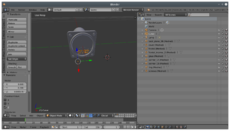
The two layers are joined by placing the SVG object using the commands of Translate according to the X, Y, Z axes. Unfortunately Blender is not a CAD and this operation is rather delicate because the movements are relative and not absolute
Do the same thing with the other SVG objects until you get the final result that we like best


This is the gauge made with the technique of 4 textures of 1024x1024 inserted in the gauge
Finally this is the final result, as you can see there are no substantial differences compared to the version with 4 textures of 1024
![This is the overall view of all the gauges made with this technique]]](/w/images/thumb/a/aa/FIAT_G91R1B_Overall_gauges_002-20181225.jpg/230px-FIAT_G91R1B_Overall_gauges_002-20181225.jpg)
This is the overall view of all the gauges made with this technique]]

![This is the overall view of all the gauges made with this technique]]](/File:FIAT_G91R1B_Overall_gauges_002-20181225.jpg)