Howto:Development of the CDU
| IMPORTANT: Some, and possibly most, of the features/ideas discussed here are likely to be affected, and possibly even deprecated, by the ongoing work on providing a property tree-based 2D drawing API accessible from Nasal using the new Canvas system available since FlightGear 2.80 (08/2012). Please see: Canvas MCDU Framework for further information
You are advised not to start working on anything directly related to this without first discussing/coordinating your ideas with other FlightGear contributors using the FlightGear developers mailing list or the Canvas subforum |

|
| This article or section contains out-of-date information
Please help improve this article by updating it. There may be additional information on the talk page. |
This page has been more a log of my (Hcc23) efforts to support the CDU of Gijs. As I am a complete newbie to FlightGear I plan to keep this log for my on sake as well as for anybody who wants to join the bandwagon... Also see: Nasal Display Matrix Framework.
In the meantime Gijs has worked quite a lot on the CDU, so a new page on the new status has been started at Howto: Coding a Boeing CDU.
General Stuff
Currently the development version of the CDU comes with a 747-400 maintained by Gijs. All path references shall start with PRE, which shall mean the directory you have that 747-400 in, e.g. $FG_ROOT/Aircraft/747-400
The CDU has mainly two parts: the graphic elements you see in the 3D Cockpit and the content of the pages displayed on the CDU.
There is a more complete site on how to make an instrument here: Creating instruments for FG.
3D Graphics
The 3D model resides in the file PRE/Models/Cockpit/Instruments/CDU/cdu.ac. This is a AC3D file format, but it should be importable by Blender.
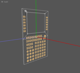
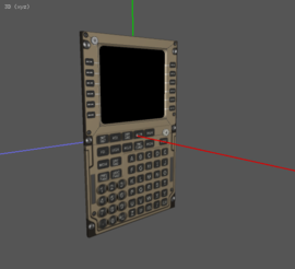
The model also specifies the model internal coordinate system. It is indicated in the pictures through the corresponding axis: X (red), Y (green), and Z (blue). The origin of this coordinate system seems to coincide with the geometric center of the back plane of the CDU, i.e. the YZ-plane is coplanar with the back of the CDU. The unit of the coordinate system is the SI unit Meter.
The 3D model has bindings defined to each button. So when a certain button is clicked, something happens. Right now most buttons are only used to open other CDU-pages.
Details of the (LCD) Screen
This is for the B777 CDU: The LCD has 14 lines with a total of 24 characters per line. The page format is formatted as follows:
- Title Field: The top line of the display area. Id identifies the subject or title of the data displayed on the page in view. It also identifies page number and the number of pages in series, e.g., 1/2 identifies a page as the first in a series of two pages.
- Left Field: 6 pairs of lines, 11 characters per line. It extends from the left side of the screen to the center. The pilot has access to one line of each pair through a LSK (Line-Select Key) on the left side of the CDU. A line pair is made up of a label and a data line.
- Right Field: This field is similar to the left field, extending from the center of the screen to the right side. Pilot access is available by a LSK on the right side.
- Scratchpad: The bottom line of the display screen. This line displays alphanumeric data or messages. Data can be entered with the alphanumeric keys or the LSK, or by the FMC. Scratchpad entry cannot, normally, be made with a FMC message in the scratchpad. Scratchpad entries are independent of page selection, and remain until cleared even when page changes occur. Scratchpad data entries and erases affect only the associated CDU. Messages can appear and be erased on both CDUs simultaneously.
CDU Coding via XML Scripts
The pages of the CDU are maintained in XML. The main CDU lives in PRE/Models/Cockpit/Instruments/CDU/CDU.xml Each page is set up in a .xml file in the PRE/Models/Cockpit/Instruments/CDU/Pages/ directory.
Here is an excerpt of CDU.xml:
<PropertyList>
	<path>cdu.ac</path>

	<model>
		<path>Aircraft/747-400/Models/Cockpit/Instruments/CDU/Pages/MENU.xml</path>
		<condition>
			<equals>
				<property>/instrumentation/cdu/display</property>
				<value>MENU</value>
			</equals>
		</condition>
	</model>
	...

	<animation>
		<type>pick</type>
		<object-name>Btn.side.r.1</object-name>
		<action>
			<button>0</button>
			<repeatable>false</repeatable>
			<binding>
				<condition>
					<equals>
						<property>/instrumentation/cdu/display</property>
						<value>NAV_RAD</value>
					</equals>
				</condition>
				<command>nasal</command>
				<script>setprop("/instrumentation/nav[1]/frequencies/selected-mhz",getprop("/instrumentation/cdu/input"));
					setprop("/instrumentation/cdu/input","");</script>
			</binding>
		</action>
	</animation>
	...
</PropertyList>
This excerpt shows the major blocks of CDU.xml: <path>...</path>, <model>...</model>, and <animation>...</animation>. <path>...</path> is unique, tt><model>...</model> and <animation>...</animation> can occur repeatedley (with different internals, of course).
Here is what these blocks do:
- <path>cdu.ac</path> : This locates the files for the 3D model
- <model>...</model>: This links in a particular page of the CDU
- <path>Aircraft/747-400/Models/Cockpit/Instruments/CDU/Pages/MENU.xml</path>: This, for example, is the link to he XML describing the MENU page
- <condition>...</condition>: When this becomes true, the page linked in above will be displayed/rendered
- <animation>...</animation>: This creates a binding between a user interaction (i.e. a mouse click) and a certain effect.
- <type>pick</type>: The type of user interaction. For the CDU these are all of type pick, i.e. a simple mouse clicks.
 See Howto:_Make_a_clickable_panel#Pick for the main article about this subject.
CDU Page Content
(or: How to put text on the screen?)
In order to put text on the CDU, one needs to create a corresponding page.
- The first step is to make the page known to the CDU. This is done by creating a corresponding
<model>...</model>section in CDU.xml. - The next step is to make a corresponding PAGE.xml in the PRE/Models/Cockpit/Instruments/CDU/Pages/ directory.
As an example, take the MENU page itself. The XML is structured as follows (This section puts the text MENU on the CDU page MENU).
Here is an excerpt from PRE/Models/Cockpit/Instruments/CDU/Pages/MENU.xml:
<PropertyList>
	<model>
		<path>Aircraft/747-400/Models/Cockpit/display-text.xml</path>
		<offsets>
			<x-m> 0.004</x-m>
			<y-m> 0.000</y-m>
			<z-m> 0.110</z-m>
		</offsets>
		<overlay>
			<params>
				<text type="string">MENU</text>
				<character-size type="double">0.007</character-size>
				<color>
					<red   type="double">0.1</red>
					<green type="double">1.0</green>
					<blue  type="double">0.1</blue>
				</color>
			</params>
		</overlay>
	</model>
	...
</PropertyList>
Here is what this does:
- <path>RENDERER.xml</path> : This locates the specifics for how to render content. (More below...)
- <offsets>...</offsets>: This gives specifics on where to render your content. The three parameters describe an offset vector from the center of the CDU 3D model (CDU.ac, see above), the unit is meter. For CDU purposes it seems that this offset is always a center-to-center offset as all the used renderers (see below for details) have a
<alignment>center-center</alignment>block in their specification. This spec also seems to take care of the normal, through an<axis-alignment>...</axis-alignment>block. - <overlay>...</overlay>: This part describes what to render. Some of the content in this block depend on your settings in the <path>...</path> block above.
Also note that all the used renderers soecify some details for the rendering internally to themselves (although the settings, at least for the ones used in the CDU, seem identical):<alignment>center-center</alignment>: The <offsets>...</offsets> block refers to a center-to-center offset from the coordinate system center, i.e. (0,0,0), to the center of the render object.<axis-alignment>yz-plane</axis-alignment>: The normal of the rendered object is orthogonal to the YZ plane, i.e. collinear with the X-axis. (Hcc23 assumes that the direction matches.)
NOTE: Please compare the XML below to $FG_ROOT/Docs/README.osgtext.
The render style display-text.xml
The corresponding file is located at the location given in the <path>...</path> block.
An excerpt from PRE/Models/Cockpit/Instruments/CDU/Pages/MENU.xml:
<params>
	<text type="string">MENU</text>
	<character-size type="double">0.007</character-size>
	<color>
		<red   type="double">0.1</red>
		<green type="double">1.0</green>
		<blue  type="double">0.1</blue>
	</color>
</params>
From what I (Hcc23) understand, this renderer requires three parameters to be set in the <params>...</params> block:
- <text type="string">....</text>: The literal string to display.
- <character-size type="double">...</character-size>: The size (Hcc23: height?) of the text. (Hcc23 assumes in meter.)
- <color>...</color>: The color, given as a RBG tupel with ranges 0 till 1 for each channel.
Hcc23: I do not yet understand what the <params>...</params> block inside display-text.xml (or any of the other renderers for that matter) actually does. My current assumption is that of a default or fall-back.The render style display-text-value.xml
The corresponding file is located at the location given in the <path>...</path> block.
An excerpt from PRE/Models/Cockpit/Instruments/CDU/Pages/NAV_RAD.xml:
<params>
	<property type="string">/instrumentation/cdu/input</property>
	<format type="string">%03.1f</format>
	<factor>1</factor>
	<character-size type="double">0.007</character-size>
	<color>
		<red   type="double">0.1</red>
		<green type="double">1.0</green>
		<blue  type="double">0.1</blue>
	</color>
</params>
From what I (Hcc23) understand, this renderer requires five parameters to be set in the <params>...</params> block:
- <property type="string">...</property>: The Property to use as a data source.
- <format type="string">%03.1f</format>: How to format this data. (Hcc23: how is a string to string conversion formatted?)
- <factor>1</factor>: Hcc23 has no idea whatsoever.
- <character-size type="double">...</character-size>: The size (Hcc23: height?) of the text. (Hcc23 assumes in meter.)
- <color>...</color>: The color, given as a RBG tupel with ranges 0 till 1 for each channel.
The render style display-number.xml
The corresponding file is located at the location given in the <path>...</path> block.
An excerpt from PRE/Models/Cockpit/Instruments/CDU/Pages/NAV_RAD.xml:
<params>
	<property type="string">/instrumentation/adf[1]/frequencies/selected-khz</property>
	<format type="string">%03.1f</format>
	<factor>1</factor>
	<character-size type="double">0.007</character-size>
	<color>
		<red   type="double">0.1</red>
		<green type="double">1.0</green>
		<blue  type="double">0.1</blue>
	</color>
</params>
From what I (Hcc23) understand, this renderer requires five parameters to be set in the <params>...</params> block:
- <property type="string">...</property>: The Property to use as a data source.
- <format type="string">%03.1f</format>: How to format this data. (Hcc23: how is a string to string conversion formatted?)
- <factor>1</factor>: Hcc23 has no idea whatsoever.
- <character-size type="double">...</character-size>: The size (Hcc23: height?) of the text. (Hcc23 assumes in meter.)
- <color>...</color>: The color, given as a RBG tupel with ranges 0 till 1 for each channel.
User Interaction
(or: How to make the CDU to actually do stuff?)
One of the main goals of developing the CDU is to actually use it as it is used in real aircraft. For that matter it has to be possible for the user (pilot) to interact with the CDU other than just looking at it and reading the currently displayed page.
This is achieved through a binding of a user interaction (e.g. a mouse click) with a certain effect. The details of these bindings are given through the<animation>...</animation>blocks in CDU.xml.
As the CDU (so far) doesn't have any moving parts (think rotating knobs, depressed buttons, etc.), the user interaction is mainly to "point and click". The animation that does that is <type>pick</type>. See Howto:_Animate_models for the main article about this subject.
 See Howto:_Make_a_clickable_panel#Pick for the main article about this subject.
Note: There are other pages in this wiki that talk about cockpit instruments which are broader (to a certain extend) and do not just focus on the CDU: Creating instruments for FG and Howto: Make a clickable panel.
CDU Buttons
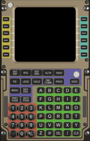
In order to better understand how to animate buttons, the functionality of the original buttons needs to be understood. The CDU has three major groups of buttons:
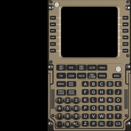
- Alpha and Numeric Buttons (green and red area in the image): The buttons are used to enter text and numerical values into the CDU. The buttons functions are straight forward, only some might need explanation:
- SP is the Space Key button. Contrary to its name it generates an underscore character:'_'.
- DEL is the DEL Key button. (It does all kinds of deleting - depending on where stuff is to be deleted...)
- CLR is the CLR Key button. It clears messages and data from the scratchpad.
- +/- is the Plus/Minus Key button. A first (momentary) push inserts a minus sign (-) into the scratchpad. A second push changes that into a plus sign (+). Subsequent pushes toggle this. (Assuming no inervening pushes of other keys are made.)
- Function and Mode Buttons (blue area in the image): These buttons are used to directly open the corresponding pages of the CDU or toggle/engage the corresponding mode of the FMS.
- the "white knob": Turning this knob adjusts the brightnes of the CDU-screen.
- Line Select Keys (LSK) (yellow and cyan area in the image): The effect of these buttons depends on the context of the screen. If a particular button has an assigned function on any particular page, this page would show a label of this button to indicate the buttons function/effect. The labels are shown on the CDU screen such that they line up with the white markers (connecting the button to the screen). Furthermore, the corresponding label would be accompanied by a '<'-prefix for the left row of buttons, or a '>'-postfix for the right row of buttons, respectively. The individual keys are identified as (left side, top to bottom) 1L,2L,3L,4L,5L,6L and (right side, top to bottom) 1R,2R,3R,4R,5R,6R.
In XML these different buttons are identified in the<animation><object-name>Btn.XXX</object-name></animation>blocks in CDU.xml. So far the following buttons are represented:Multifunction buttons:
Btn.side.l.1, Btn.side.l.2, Btn.side.l.3, Btn.side.l.5, Btn.side.l.6
Btn.side.r.1, Btn.side.r.6
Direct Access buttons:
Btn.init-ref, Btn.nav-rad, Btn.dep-arr, Btn.menu
Alphanumerical buttons:
Btn.zero, Btn.num1, Btn.num2, Btn.num3, Btn.num4, Btn.num5, Btn.num6, Btn.num7, Btn.num8, Btn.num9,
Btn.A, Btn.B, Btn.C, Btn.D, Btn.E, Btn.F, Btn.G, Btn.H, Btn.I, Btn.J, Btn.K, Btn.L, Btn.M,
Btn.N, Btn.O, Btn.P ,Btn.Q ,Btn.R ,Btn.S ,Btn.T ,Btn.U ,Btn.V ,Btn.W ,Btn.X ,Btn.Y, Btn.Z,
Btn.period, Btn.clr
On Linux one can get a list of the currently implemented buttons with the shell command
more PRE/Models/Cockpit/Instruments/CDU/CDU.xml | grep "<object-name>Btn*". Don't forget to replace the PRE with your settigs if you copy/paste the command.Binding Buttons
(or: How to make the buttons do stuff)
 See Bindings for the main article about this subject.
The simplest group of buttons to deal with are the function and mode keys (the blue shaded group). As they are intended to switch to a certain page of the CDU, all that is necessary is to manipulate the corresponding property that is checked when CDU.xml is used to decide on which page to display. (See above for how this page selection is done.)
Again, an excerpt from CDU.xml:
<animation>
	<type>pick</type>
	<object-name>Btn.init-ref</object-name>
	<action>
		<button>0</button>
		<repeatable>false</repeatable>
		<binding>
			<command>property-assign</command>
			<property>/instrumentation/cdu/display</property>
			<value type="string">INIT_REF</value>
		</binding>
	</action>
</animation>
As already mentioned, is animation is of <type>pick</type>. See Howto:_Make_a_clickable_panel#Pick for the main article about this subject.
The relevant part is what happens in the <binding>...</binding> section:
- <command>property-assign</command>: The type of activity that the action is bound to. In this case a simple direct setting of a property in the tree.
- <property>/instrumentation/cdu/display</property>: The property that is being set. Here the one that holds the information which CDU page is to be displayed
- <value type="string">INIT_REF</value>: The actual value, i.e. the page that is to be displayed. Make sure to check the spelling as CDU.xml uses a equality condition to find a match.
Next on the list are the alphanumerical buttons. These buttons cause an input of data into the CDU, so they are a little more complex as they have to deal with the (simulated) smarts of the CDU.And another excerpt from CDU.xml:
<animation>
	<type>pick</type>
	<object-name>Btn.zero</object-name>
	<action>
		<button>0</button>
		<repeatable>false</repeatable>
		<binding>
			<command>nasal</command>
			<script>setprop("/instrumentation/cdu/input",getprop("/instrumentation/cdu/input")~'0');</script>
		</binding>
	</action>
</animation>
This section deals with the 0 (numerical zero) button. Compare the <binding>...</binding> block of this button to the direct access one above:
- <command>nasal</command>: The effect of this button being (left-)clicked is the execution of a Nasal script.
- <script>...</script>: The script to be executed is either directly written in here (like in this example) or linked in via the script files path and file name.
 See Nasal for the main article about this subject.
The most cumbersome buttons are the line select keys. As their function depends on the current state of the CDU, the corresponding XML requires some conditional checks.
And yet another excerpt from CDU.xml:
<animation>
	<type>pick</type>
	<object-name>Btn.side.l.1</object-name>
	<action>
		<button>0</button>
		<repeatable>false</repeatable>
		<binding>
			<condition>
				<equals>
					<property>/instrumentation/cdu/display</property>
					<value>INIT_REF</value>
				</equals>
			</condition>
			<command>property-assign</command>
			<property>/instrumentation/cdu/display</property>
			<value type="string">IDENT</value>
		</binding>
		<binding>
			<condition>
				<equals>
					<property>/instrumentation/cdu/display</property>
					<value>NAV_RAD</value>
				</equals>
			</condition>
			<command>nasal</command>
			<script>setprop("/instrumentation/nav[0]/frequencies/selected-mhz",getprop("/instrumentation/cdu/input"));
					setprop("/instrumentation/cdu/input","");</script>
		</binding>
		<binding>
			<condition>
				<equals>
					<property>/instrumentation/cdu/display</property>
					<value>TO_REF</value>
				</equals>
			</condition>
			<command>nasal</command>
			<script>setprop("/instrumentation/fmc/to-flap",getprop("/instrumentation/cdu/input"));
					setprop("/instrumentation/cdu/input","");</script>
		</binding>
	</action>
</animation>
This is conceptually identical to the alphanumeric buttons, just that several bindings (depending on the page) are present. The <condition>...</condition> block checks the same property that is used in CDU.xml to decide on the curret page: /instrumentation/cdu/display.
(Hcc23 wonders if the condition on the page could be put somewhere else in order to keep things slightly more organized (by pages that is, and not by buttons...))
CDU Pages
This section briefly lists all available pages and their function and/or current capabilities.
APPROACH REF
DEP/ARR INDEX
IDENT
INIT/REF INDEX
PERF INIT
POS INIT
POS REF
TAKEOFF REF
MENU
The starting page after the AC is initialized.
NAV RADIO
It displays radio frequencies. Those frequencies can be set through the generic radio system (accesible via Equipment > Radio Settings menu). In the near future the pilot will set these through the CDU. The pilot can already configure the takeoff flap setting through the CDU.
- <type>pick</type>: The type of user interaction. For the CDU these are all of type pick, i.e. a simple mouse clicks.
